EP0706660B1 - Verfahren und vorrichtung zur erzeugung einer graphischen echtzeit-richtungsinformation für detektierte objektspuren - Google Patents
Verfahren und vorrichtung zur erzeugung einer graphischen echtzeit-richtungsinformation für detektierte objektspuren Download PDFInfo
- Publication number
- EP0706660B1 EP0706660B1 EP94916900A EP94916900A EP0706660B1 EP 0706660 B1 EP0706660 B1 EP 0706660B1 EP 94916900 A EP94916900 A EP 94916900A EP 94916900 A EP94916900 A EP 94916900A EP 0706660 B1 EP0706660 B1 EP 0706660B1
- Authority
- EP
- European Patent Office
- Prior art keywords
- objects
- recording time
- image detector
- during
- light
- Prior art date
- Legal status (The legal status is an assumption and is not a legal conclusion. Google has not performed a legal analysis and makes no representation as to the accuracy of the status listed.)
- Expired - Lifetime
Links
- 238000000034 method Methods 0.000 title claims description 44
- 230000008569 process Effects 0.000 title description 7
- 239000002245 particle Substances 0.000 claims description 29
- 230000035945 sensitivity Effects 0.000 claims description 13
- 238000003384 imaging method Methods 0.000 claims description 11
- 230000008859 change Effects 0.000 claims description 6
- 230000003287 optical effect Effects 0.000 claims description 6
- 238000012986 modification Methods 0.000 claims description 2
- 230000004048 modification Effects 0.000 claims description 2
- 238000000149 argon plasma sintering Methods 0.000 claims 1
- 238000011144 upstream manufacturing Methods 0.000 claims 1
- 239000000306 component Substances 0.000 description 11
- 238000000917 particle-image velocimetry Methods 0.000 description 9
- 210000004027 cell Anatomy 0.000 description 7
- 238000011156 evaluation Methods 0.000 description 7
- 238000002474 experimental method Methods 0.000 description 7
- 239000012530 fluid Substances 0.000 description 7
- 238000005259 measurement Methods 0.000 description 6
- 230000001360 synchronised effect Effects 0.000 description 6
- 230000005540 biological transmission Effects 0.000 description 5
- 238000005516 engineering process Methods 0.000 description 5
- 238000005286 illumination Methods 0.000 description 3
- 230000010354 integration Effects 0.000 description 3
- 238000000691 measurement method Methods 0.000 description 3
- 238000000037 particle-tracking velocimetry Methods 0.000 description 2
- 238000012545 processing Methods 0.000 description 2
- 238000000827 velocimetry Methods 0.000 description 2
- 230000001594 aberrant effect Effects 0.000 description 1
- 210000000601 blood cell Anatomy 0.000 description 1
- 238000010276 construction Methods 0.000 description 1
- 239000008358 core component Substances 0.000 description 1
- 238000001514 detection method Methods 0.000 description 1
- 230000000694 effects Effects 0.000 description 1
- 238000010327 methods by industry Methods 0.000 description 1
- 239000004065 semiconductor Substances 0.000 description 1
- 230000008685 targeting Effects 0.000 description 1
Images


Classifications
-
- G—PHYSICS
- G01—MEASURING; TESTING
- G01P—MEASURING LINEAR OR ANGULAR SPEED, ACCELERATION, DECELERATION, OR SHOCK; INDICATING PRESENCE, ABSENCE, OR DIRECTION, OF MOVEMENT
- G01P5/00—Measuring speed of fluids, e.g. of air stream; Measuring speed of bodies relative to fluids, e.g. of ship, of aircraft
- G01P5/001—Full-field flow measurement, e.g. determining flow velocity and direction in a whole region at the same time, flow visualisation
-
- G—PHYSICS
- G01—MEASURING; TESTING
- G01P—MEASURING LINEAR OR ANGULAR SPEED, ACCELERATION, DECELERATION, OR SHOCK; INDICATING PRESENCE, ABSENCE, OR DIRECTION, OF MOVEMENT
- G01P13/00—Indicating or recording presence, absence, or direction, of movement
- G01P13/02—Indicating direction only, e.g. by weather vane
- G01P13/04—Indicating positive or negative direction of a linear movement or clockwise or anti-clockwise direction of a rotational movement
- G01P13/045—Indicating positive or negative direction of a linear movement or clockwise or anti-clockwise direction of a rotational movement with speed indication
Definitions
- the invention relates to a method for determining the direction of recorded Traces of moving objects directly on an image detector.
- the detected Object traces receive graphical information in arrow or Vector shape.
- the objects can be illuminated or self-illuminating bodies act under different sizes. Illuminated tiny particles such as Molecules or particles that e.g. are also shipped in a current, but also larger illuminated moving objects, which are imaged on an image detector as a track will.
- a prerequisite for the process is that the objects during the Exposure or integration time of the image detector tracks on the detector element to draw. It is characteristic of the method that the detected object tracks at the recording either by changing the incident on the image detector Light output or by changing the sensitivity of the image detector with a graphic directional information in arrow or vector form.
- Such Track recordings of illuminated or self-illuminating particles can also be found in other object size ranges e.g. in process engineering, it being the Tracking larger particles goes, or in physics, where traces of Small particles and core components can be made visible, or in medical technology in tracking the movement of blood cells.
- a rough subdivision of existing measuring methods to record the Particle movement occurs depending on whether at a fixed point in the measuring space over a Period is measured, or whether an extended area of the measuring room to one fixed time is measured [2]. If one classifies the measuring method according to this, it represents it is found that point measuring methods are mostly time-averaged, and full-field measuring methods ("Whole Field Techniques") mainly provide instant movement information.
- the present invention belongs to the field of full-field measurement methods in which Object traces in an entire image field (section from a measuring room) to a fixed one Point in time can be recorded and evaluated.
- Another new coding method is based on the fact that particle traces with a Sensitivity leap of the detector can be recorded in this way in the To record directional information on gray values of the image pixels. This one too The resulting image must be subsequently processed in order to draw up vector arrows to draw the particle traces [10].
- This procedure is very similar to the procedure [11], in which the same is achieved, but by changing the lighting during the recording. Both [10] and [11] are based on the evaluation of Differences in brightness such as occur in conventional photographs and to cause no measurable change in object contours. From broadening recorded tracks due to differences in lighting in any way is therefore in [10] and [11] no speech. Rather, it also applies to these two methods that one first arrives at a vector field through a subsequent evaluation.
- the object of the invention is therefore to create a method which is quick and vectorization of an image field in a simple and convenient manner Object traces enabled.
- Another object of the invention is a device for To indicate implementation of the procedure.
- the solution to this problem is based on the idea that during the recording a suitable change in the detected light output of moving objects or by changing the sensitivity of the image detector on the detector mapped track can be changed in width. So at the end of a track, i.e. towards the end of the recording time for a picture, a sudden change in the Track thickness are generated, which corresponds graphically to an arrow or vector shape. For example, in one embodiment of the invention (modification of the Lighting) the fact that points (objects) shining at different intensities same size when imaging through a lens on differently sized pixels of the detector area.
- the latter depends on together with that at high Light output also from the optical axis distant edge rays, which by the Lens are going to be detectable, but the conventional imaging errors of one Lens or a lens system subject, with the result that the pixel at constant detector sensitivity is increased.
- the effect of Pixel broadening can also be achieved in that with constant Illumination of the object points clearly the sensitivity of the image detector is increased, whereby the aberrant marginal rays in the Imaging become detectable and lead to a broadening of the image point.
- the imaging optics take place with the aim of specifically targeting the object track on the image detector defocus and thus broaden.
- the defocusing takes place in such a way that the track is also depicted as an arrow (vector).
- the present invention allows vectorization of the particle traces from one captured image field directly during the recording.
- the number of detected and already evaluated by the invention when it was recorded existing image fields per second is only through the image acquisition system specified (e.g. video standard) and can be used when using High speed video systems in the range of several thousand frames per Second.
- the invention thus enables real-time vectorization of track recordings directly when recording and can do what seemed previously impossible.
- the invention not only can the described measuring tasks be incomparably faster, but also perform much less expensive than previously used full-field measurement methods.
- the invention can e.g. can be realized by the Change in the illuminating power of the objects (1) in a light section (5), whereby either the laser light source (2) is modulated directly or optically active components (4) take over the light power modulation.
- Optically active components (6) can but also cause a change in the detected scattered light output at the receiving end.
- An embodiment is also conceivable in which either the transmission optics (10) or the Receiving optics (7) or the image detector (3) by adjusting elements (11,9,8) during the Process or defocus.
- Figure 2 shows a typical track recording that with an inventive Embodiment was obtained.
- the graphic direction information is shown as an arrow or Vector shape clearly.
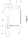
- FIG. 3 shows an embodiment of the invention in which the light beam (31) of a laser (20) is guided through an optically active component (21) which Light output changed during image acquisition.
- the laser beam then experiences an expansion by a transmission optics (22) and forms a light section (25) in which move the objects to be tracked (23).
- the light scattered by the objects is connected via a lens (27) to the image detector (28), which is connected to the control unit (29) optically active component (21) is synchronized.
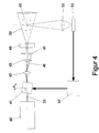
- FIG. 4 gives a special embodiment of the arrangement shown in FIG. 3 again, in which a Bragg cell (41) is used to modulate the illuminating light output is used.
- the beam (39) of a laser (40) is through a Bragg cell (41) guided, which is driven by a control unit (54).
- a control unit (54) By suitable Modulation of the driver frequency, the light output in the by a transmission optics (44) generated light section (50) changed during the recording.
- the through the Bragg cell (41) higher-order rays (48) are generated by a suitable lens Mask arrangement (42,43,49) hidden.
- the objects (45) outgoing light is imaged via a lens (52) onto the image detector (53), which with the control unit (54) of the Bragg cell (41) is synchronized.
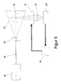
- the light beam (66) from a laser (55) is transformed into one by means of an optical transmission system (56)
- Objects (57) scatter the light through an optically active Component (61) and a lens (62) on the image detector (63) is guided.
- the optically active component (61) changes the image detector (63) during the recording led light output and is with the image detector via a control or driver unit (64) synchronized.
- the object track e.g. at the end of a recording on the image detector changed or broadened in such a way that graphic directional information is created.
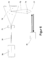
- FIG. 6 shows that a light beam (79) from a laser (70) through an optical transmitter (71) is expanded and forms a light plane (74) in which those to be tracked Move objects (72).
- the scattered light (75) is on the lens (76) Image detector (77) guided, the sensitivity during recording via a control or driver unit (78) is changed.
- the sensitivity e.g. at the end of the acquisition or integration time of the image detector, the object tracks are received the desired graphic direction information.
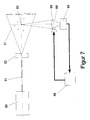
- Figure 7 shows an embodiment of the invention in which the light beam (81) one Laser (80) is expanded by a transmission optics (82) and a light section (91) forms.
- Objects (83) that move in the light section scatter the light that passes through a Lens (89) is imaged on the image detector (90).
- the lens (89) is suitably shifted (89 ') during the recording, so that the recorded object track is widened by the desired defocusing, which can be used to generate directional information.
- the lens (89, 89 ') or the entire receiving optics are moved via a Driver or control unit which is synchronized with the image detector (90).
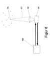
- FIG. 8 shows that the invention is not restricted to the illumination of objects. but that the traces of self-illuminating objects (95) are also evaluated can be provided with a graphical direction information in real time can.
- the light from the objects (97) is applied to the image detector via a lens (98) (99), whose sensitivity during the recording time e.g. electronically is changed via a driver or control unit (100), whereby the recorded object tracks can be widened and a graphic Direction information can be generated.
Landscapes
- Physics & Mathematics (AREA)
- General Physics & Mathematics (AREA)
- Engineering & Computer Science (AREA)
- Aviation & Aerospace Engineering (AREA)
- Length Measuring Devices By Optical Means (AREA)
- Investigating Or Analysing Materials By Optical Means (AREA)
Applications Claiming Priority (3)
| Application Number | Priority Date | Filing Date | Title |
|---|---|---|---|
| DE4321876 | 1993-07-01 | ||
| DE4321876A DE4321876C1 (de) | 1993-07-01 | 1993-07-01 | Verfahren und Vorrichtung zur Erzeugung einer graphischen Echtzeit-Richtungsinformation für detektierte Objektspuren |
| PCT/DE1994/000653 WO1995001572A1 (de) | 1993-07-01 | 1994-06-09 | Verfahren und vorrichtung zur erzeugung einer graphischen echtzeit-richtungsinformation für detektierte objektspuren |
Publications (2)
| Publication Number | Publication Date |
|---|---|
| EP0706660A1 EP0706660A1 (de) | 1996-04-17 |
| EP0706660B1 true EP0706660B1 (de) | 1998-08-19 |
Family
ID=6491678
Family Applications (1)
| Application Number | Title | Priority Date | Filing Date |
|---|---|---|---|
| EP94916900A Expired - Lifetime EP0706660B1 (de) | 1993-07-01 | 1994-06-09 | Verfahren und vorrichtung zur erzeugung einer graphischen echtzeit-richtungsinformation für detektierte objektspuren |
Country Status (6)
| Country | Link |
|---|---|
| US (1) | US5812248A (da) |
| EP (1) | EP0706660B1 (da) |
| JP (1) | JPH09500206A (da) |
| DE (1) | DE4321876C1 (da) |
| DK (1) | DK0706660T3 (da) |
| WO (1) | WO1995001572A1 (da) |
Families Citing this family (10)
| Publication number | Priority date | Publication date | Assignee | Title |
|---|---|---|---|---|
| ES2155331B1 (es) * | 1998-05-13 | 2001-12-01 | Univ Madrid Carlos Iii | Procedimiento de velocimetria por correlacion de imagenes de particulas con resolucion espacial menor que el tamaño de la ventana de interrogacion. |
| DE19911277C2 (de) * | 1999-03-13 | 2001-04-26 | Lavision Gmbh | Verfahren und Vorrichtung zur Erfassung des Ortes eines Lichtpunktes und des Zeitpunktes, zu dem sich der Lichtpunkt am erfaßten Ort befindet |
| DE19928698A1 (de) * | 1999-06-23 | 2000-09-21 | Deutsch Zentr Luft & Raumfahrt | Vorrichtung zur Durchführung von PIV-Messungen |
| DE10239468A1 (de) * | 2002-08-28 | 2004-03-11 | Sick Ag | Objekterfassung |
| US7177487B2 (en) * | 2003-04-21 | 2007-02-13 | Baxter International Inc. | Determination of particle size by image analysis |
| US20060175561A1 (en) * | 2005-02-09 | 2006-08-10 | Innovative Scientific Solutions, Inc. | Particle shadow velocimetry |
| DE102009020876A1 (de) * | 2009-05-12 | 2010-11-18 | Deutsches Zentrum für Luft- und Raumfahrt e.V. | LED-Partikelströmungsfeldmessung |
| CN105807093B (zh) * | 2016-04-18 | 2018-11-16 | 北京航空航天大学 | 一种基于粒子图像测速技术的加速度测量方法及装置 |
| JPWO2018193704A1 (ja) * | 2017-04-20 | 2020-02-27 | ソニー株式会社 | 信号処理システム、信号処理装置、及び信号処理方法 |
| CN117348266B (zh) * | 2023-12-06 | 2024-01-30 | 中国航空工业集团公司沈阳空气动力研究所 | 一种用于piv系统的激光散斑生成装置与方法 |
Family Cites Families (7)
| Publication number | Priority date | Publication date | Assignee | Title |
|---|---|---|---|---|
| DE2937003A1 (de) * | 1979-09-13 | 1981-04-02 | Prof.Dr.rer.nat. Johann 6109 Mühltal Heber | Verfahren zur bestimmung der stroemungsgeschwindigkeit in hochgeschwindigkeitsstroemungsfeldern und laser-anemometer zur durchfuehrung des verfahrens |
| US4429995A (en) * | 1980-07-21 | 1984-02-07 | National Research Development Corporation | Two dimensinal flow analyzer |
| JPS5757265A (en) * | 1980-09-25 | 1982-04-06 | Mitsubishi Heavy Ind Ltd | Method for measuring flow trace speed |
| US4866639A (en) * | 1987-03-09 | 1989-09-12 | University Of Illinois | Method and apparatus for determining the direction of motion in multiple exposure velocimetry |
| US4988191A (en) * | 1987-03-09 | 1991-01-29 | University Of Illinois | Electro-optical method and system for determining the direction of motion in double-exposure velocimetry by shifting an optical image field |
| US5153665A (en) * | 1991-06-14 | 1992-10-06 | The United States Of America As Represented By The Administrator Of The National Aeronautics And Space Administration | Vaporizing particle velocimeter |
| US5491642A (en) * | 1993-12-03 | 1996-02-13 | United Technologies Corporation | CCD based particle image direction and zero velocity resolver |
-
1993
- 1993-07-01 DE DE4321876A patent/DE4321876C1/de not_active Expired - Fee Related
-
1994
- 1994-06-09 US US08/571,910 patent/US5812248A/en not_active Expired - Fee Related
- 1994-06-09 JP JP7503203A patent/JPH09500206A/ja active Pending
- 1994-06-09 DK DK94916900T patent/DK0706660T3/da active
- 1994-06-09 EP EP94916900A patent/EP0706660B1/de not_active Expired - Lifetime
- 1994-06-09 WO PCT/DE1994/000653 patent/WO1995001572A1/de not_active Ceased
Also Published As
| Publication number | Publication date |
|---|---|
| DE4321876C1 (de) | 1994-10-06 |
| WO1995001572A1 (de) | 1995-01-12 |
| US5812248A (en) | 1998-09-22 |
| JPH09500206A (ja) | 1997-01-07 |
| EP0706660A1 (de) | 1996-04-17 |
| DK0706660T3 (da) | 1999-05-25 |
Similar Documents
| Publication | Publication Date | Title |
|---|---|---|
| DE69207176T2 (de) | Optischer Sensor | |
| EP0829726B1 (de) | Verfahren und Vorrichtung zum Erfassen 3-dimensionaler Strömungsstrukturen | |
| DE2558392A1 (de) | Partikelanalysator | |
| EP0307668B1 (de) | Verfahren und Vorrichtung zur Messung der Strömungsgeschwindigkeit in Windkanälen | |
| DE60036467T2 (de) | Verfahren und vorrichtung zur dopplergeschwindigkeitsmessung | |
| DE4321876C1 (de) | Verfahren und Vorrichtung zur Erzeugung einer graphischen Echtzeit-Richtungsinformation für detektierte Objektspuren | |
| DE19628348C1 (de) | Meßsonde zur in-line-Bestimmung der Größe von bewegten Partikeln in transparenten Medien | |
| EP0930506A1 (de) | Kalibrierverfahren für Laserlichtschnittverfahren | |
| EP1049064A2 (de) | Verkehrsüberwachungseinrichtung mit Polarisationsfiltern | |
| EP1039289A2 (de) | Verfahren und Einrichtung zur Bestimmung der Geschwindigkeit und der Grösse von Partikeln | |
| EP0467127A2 (de) | Verfahren und Anordung zur optischen Erfassung und Auswertung von Streulichtsignalen | |
| DE19720330C1 (de) | Verfahren und Vorrichtung zur Messung von Spannungen in Glasscheiben mit Hilfe des Streulichtverfahrens | |
| EP0346601B1 (de) | Verfahren und Vorrichtung zur Messung der Strömungsgeschwindigkeit, insbesondere in einem Windkanal | |
| DE102023113046B4 (de) | Verfahren und Vorrichtung zur Messung von Strömungsgeschwindigkeiten mittels in-line Particle Image Velocimetry | |
| DE60110341T2 (de) | Anordnung und Verfahren zur Entfernungsmessung | |
| DE3143475A1 (de) | Lichtelektrische kraftmesseinrichtung (optoelektronische kraftmesseinrichtung) | |
| DE4102855C2 (de) | Verfahren und Vorrichtung zur Bestimmung von lokalen Dichteschwankungen in Grenzschichten eines umströmten Körpers | |
| DE102005028893B4 (de) | Vorrichtung zur Partikeldetektion in einer tiefenbegrenzten Lichtscheibe | |
| DE9104596U1 (de) | Vorrichtung zur Qualitätskontrolle von transparenten Kunststoffen | |
| DE19525847C2 (de) | Verfahren und Vorrichtung zur Bestimmung des Durchmessers von Teilchen | |
| DE4313497A1 (de) | Verfahren und Gerät zum Bestimmen von Richtung und Geschwindigkeit eines Objektes | |
| DE3716249C2 (da) | ||
| DE2428594A1 (de) | Verfahren und vorrichtung zur erkennung von bereichen andersartiger oberflaechenstruktur auf werkstuecken mit ansonsten glatter oberflaeche | |
| DE2703504A1 (de) | Vorrichtung zur modulation eines bewegten lichtstrahls, dessen von einer lichtquelle ausgehender lichtstrom detektiert wird | |
| DE2905483A1 (de) | Verfahren und einrichtung zur beruehrungslosen messung der geschwindigkeit von teilchen |
Legal Events
| Date | Code | Title | Description |
|---|---|---|---|
| PUAI | Public reference made under article 153(3) epc to a published international application that has entered the european phase |
Free format text: ORIGINAL CODE: 0009012 |
|
| 17P | Request for examination filed |
Effective date: 19951219 |
|
| AK | Designated contracting states |
Kind code of ref document: A1 Designated state(s): DK FR GB |
|
| 17Q | First examination report despatched |
Effective date: 19970612 |
|
| GRAG | Despatch of communication of intention to grant |
Free format text: ORIGINAL CODE: EPIDOS AGRA |
|
| GRAG | Despatch of communication of intention to grant |
Free format text: ORIGINAL CODE: EPIDOS AGRA |
|
| GRAH | Despatch of communication of intention to grant a patent |
Free format text: ORIGINAL CODE: EPIDOS IGRA |
|
| GRAH | Despatch of communication of intention to grant a patent |
Free format text: ORIGINAL CODE: EPIDOS IGRA |
|
| GRAA | (expected) grant |
Free format text: ORIGINAL CODE: 0009210 |
|
| AK | Designated contracting states |
Kind code of ref document: B1 Designated state(s): DK FR GB |
|
| GBT | Gb: translation of ep patent filed (gb section 77(6)(a)/1977) |
Effective date: 19981006 |
|
| ET | Fr: translation filed | ||
| REG | Reference to a national code |
Ref country code: DK Ref legal event code: T3 |
|
| PGFP | Annual fee paid to national office [announced via postgrant information from national office to epo] |
Ref country code: FR Payment date: 19990531 Year of fee payment: 6 |
|
| PGFP | Annual fee paid to national office [announced via postgrant information from national office to epo] |
Ref country code: GB Payment date: 19990609 Year of fee payment: 6 |
|
| PGFP | Annual fee paid to national office [announced via postgrant information from national office to epo] |
Ref country code: DK Payment date: 19990616 Year of fee payment: 6 |
|
| PLBE | No opposition filed within time limit |
Free format text: ORIGINAL CODE: 0009261 |
|
| STAA | Information on the status of an ep patent application or granted ep patent |
Free format text: STATUS: NO OPPOSITION FILED WITHIN TIME LIMIT |
|
| 26N | No opposition filed | ||
| PG25 | Lapsed in a contracting state [announced via postgrant information from national office to epo] |
Ref country code: GB Free format text: LAPSE BECAUSE OF NON-PAYMENT OF DUE FEES Effective date: 20000609 Ref country code: DK Free format text: LAPSE BECAUSE OF NON-PAYMENT OF DUE FEES Effective date: 20000609 |
|
| GBPC | Gb: european patent ceased through non-payment of renewal fee |
Effective date: 20000609 |
|
| REG | Reference to a national code |
Ref country code: DK Ref legal event code: EBP |
|
| PG25 | Lapsed in a contracting state [announced via postgrant information from national office to epo] |
Ref country code: FR Free format text: LAPSE BECAUSE OF NON-PAYMENT OF DUE FEES Effective date: 20010228 |
|
| REG | Reference to a national code |
Ref country code: FR Ref legal event code: ST |