EP0706771A2 - Système modulaire de meubles - Google Patents
Système modulaire de meubles Download PDFInfo
- Publication number
- EP0706771A2 EP0706771A2 EP95116116A EP95116116A EP0706771A2 EP 0706771 A2 EP0706771 A2 EP 0706771A2 EP 95116116 A EP95116116 A EP 95116116A EP 95116116 A EP95116116 A EP 95116116A EP 0706771 A2 EP0706771 A2 EP 0706771A2
- Authority
- EP
- European Patent Office
- Prior art keywords
- furniture system
- hollow column
- column
- bar
- designed
- Prior art date
- Legal status (The legal status is an assumption and is not a legal conclusion. Google has not performed a legal analysis and makes no representation as to the accuracy of the status listed.)
- Granted
Links
- 238000005253 cladding Methods 0.000 claims abstract description 27
- 238000003860 storage Methods 0.000 claims description 13
- 230000000087 stabilizing effect Effects 0.000 claims description 12
- 230000003019 stabilising effect Effects 0.000 abstract 2
- 230000006641 stabilisation Effects 0.000 description 11
- 238000011105 stabilization Methods 0.000 description 11
- 229910052751 metal Inorganic materials 0.000 description 6
- 239000002184 metal Substances 0.000 description 6
- 230000006978 adaptation Effects 0.000 description 5
- 238000010276 construction Methods 0.000 description 4
- 238000004519 manufacturing process Methods 0.000 description 3
- XEEYBQQBJWHFJM-UHFFFAOYSA-N Iron Chemical compound [Fe] XEEYBQQBJWHFJM-UHFFFAOYSA-N 0.000 description 2
- 235000013305 food Nutrition 0.000 description 2
- 239000011796 hollow space material Substances 0.000 description 2
- 239000000463 material Substances 0.000 description 2
- 239000004033 plastic Substances 0.000 description 2
- 240000007124 Brassica oleracea Species 0.000 description 1
- 235000003899 Brassica oleracea var acephala Nutrition 0.000 description 1
- 235000011301 Brassica oleracea var capitata Nutrition 0.000 description 1
- 235000001169 Brassica oleracea var oleracea Nutrition 0.000 description 1
- WYTGDNHDOZPMIW-RCBQFDQVSA-N alstonine Natural products C1=CC2=C3C=CC=CC3=NC2=C2N1C[C@H]1[C@H](C)OC=C(C(=O)OC)[C@H]1C2 WYTGDNHDOZPMIW-RCBQFDQVSA-N 0.000 description 1
- 229910052782 aluminium Inorganic materials 0.000 description 1
- XAGFODPZIPBFFR-UHFFFAOYSA-N aluminium Chemical compound [Al] XAGFODPZIPBFFR-UHFFFAOYSA-N 0.000 description 1
- 238000004873 anchoring Methods 0.000 description 1
- 235000021170 buffet Nutrition 0.000 description 1
- 230000001419 dependent effect Effects 0.000 description 1
- 210000005069 ears Anatomy 0.000 description 1
- 238000001125 extrusion Methods 0.000 description 1
- 230000002349 favourable effect Effects 0.000 description 1
- 238000007373 indentation Methods 0.000 description 1
- 238000003780 insertion Methods 0.000 description 1
- 230000037431 insertion Effects 0.000 description 1
- 229910052742 iron Inorganic materials 0.000 description 1
- 238000005304 joining Methods 0.000 description 1
- 238000003801 milling Methods 0.000 description 1
- 238000012986 modification Methods 0.000 description 1
- 230000004048 modification Effects 0.000 description 1
- 229910052759 nickel Inorganic materials 0.000 description 1
- PXHVJJICTQNCMI-UHFFFAOYSA-N nickel Substances [Ni] PXHVJJICTQNCMI-UHFFFAOYSA-N 0.000 description 1
- 230000003287 optical effect Effects 0.000 description 1
- 238000004080 punching Methods 0.000 description 1
- 230000005855 radiation Effects 0.000 description 1
- 239000007787 solid Substances 0.000 description 1
- 239000002023 wood Substances 0.000 description 1
Images


Classifications
-
- E—FIXED CONSTRUCTIONS
- E04—BUILDING
- E04H—BUILDINGS OR LIKE STRUCTURES FOR PARTICULAR PURPOSES; SWIMMING OR SPLASH BATHS OR POOLS; MASTS; FENCING; TENTS OR CANOPIES, IN GENERAL
- E04H1/00—Buildings or groups of buildings for dwelling or office purposes; General layout, e.g. modular co-ordination or staggered storeys
- E04H1/12—Small buildings or other erections for limited occupation, erected in the open air or arranged in buildings, e.g. kiosks, waiting shelters for bus stops or for filling stations, roofs for railway platforms, watchmen's huts or dressing cubicles
- E04H1/1205—Small buildings erected in the open air
- E04H1/1222—Sales kiosks
-
- A—HUMAN NECESSITIES
- A47—FURNITURE; DOMESTIC ARTICLES OR APPLIANCES; COFFEE MILLS; SPICE MILLS; SUCTION CLEANERS IN GENERAL
- A47F—SPECIAL FURNITURE, FITTINGS, OR ACCESSORIES FOR SHOPS, STOREHOUSES, BARS, RESTAURANTS OR THE LIKE; PAYING COUNTERS
- A47F9/00—Shop, bar, bank or like counters
Definitions
- the invention relates to a modular furniture system, in particular for bar counters, consisting of lined up, identical basic modules which can be joined together to build variable furniture shapes.
- Modular furniture systems of this type are generally constructed in such a way that several basic modules of the same type are joined to one another, but in particular for bar counters the furniture substructure is designed as a solid base in order to ensure the appropriate stability.
- the counter surface is often designed as a continuous plate, so that certain shapes, generally an elongated shape, are specified. This makes it difficult to adapt to the existing base area of the bar or the catering area. This is particularly disadvantageous if such a bar counter is to be used at different locations, for example as a buffet service.
- the construction and dismantling of such a counter for mobile use is therefore very labor intensive.
- the relatively massive design of the bar base makes transportation extremely difficult.
- the cladding element (decorative panel) is attached to a base plate, which, however, is relatively thick-walled for reasons of stability.
- the described fastening of the decorative panel by means of a flat iron, a cranked angle rail and a corresponding milling on the decorative panel is relatively complex.
- the object of the invention is to create a modular furniture system, in particular for bar counters, which can be assembled and disassembled in a simple manner, is suitable for building variable and stable furniture shapes and is easy to transport.
- the furniture system thus formed is easily assembled and disassembled.
- the basic module which can be arranged in any order, can be used to create a variety of furniture shapes, for example a quarter circle, a semicircle, a three-quarter circle, a full circle or even serpentine bar counter shapes. This enables an optimal adaptation to the given space.
- the bar counter created in this way can be shortened or lengthened for special occasions, and its basic shape can be varied. If, for example, more dance floor is needed for a certain celebration, a section of the bar counter created in this way can be easily implemented.
- the proposed modular furniture system is therefore also suitable for use in sales stands, for example in trade fair construction or in department stores.
- the proposed thin-walled, flat cladding elements can be formed from any materials, such as metal, wood or plastic, since they have sufficient stability due to the detachable connection to the tubular, supporting hollow column. This applies in particular to the execution by means of a plug connection and Stabilizing strips, which also make it easier to assemble the modular furniture system.
- the proposed hollow column has a high stability due to the tubular design, so that the necessary load-bearing capacity is given for a variety of storage areas.
- supply lines and components for example loudspeakers or light sources
- the detachable connections to the cladding elements can also only be accessible from the hollow of the hollow column, so that there is a smooth-faced connection with the cladding elements that is hardly visible from the outside.
- blinds or roller shutters can also be integrated in the hollow space of the tubular hollow column, so that a sales stand designed in this way or a bar counter can be locked in a simple manner against unauthorized access. This applies in particular to sales stands at trade fairs and similar sales events.
- This door element is pivotally attached to an end hollow column.
- This door element is preferably designed as a roll container, so that in addition to the storage of goods to be presented, information media, for example a computer monitor or a television set, can also be integrated therein.
- information media for example a computer monitor or a television set
- the pivoting of the door element allows the direction of view of the monitor to be aligned with the visitors sitting at the counter or the information stand.
- This door also serves in conjunction with the previously mentioned roller shutters to close the sales booth, if necessary.
- FIG. 1 shows a front view of a modular furniture system 1, of which a central basic module 2 is shown with further modules adjoining it laterally.
- the basic module 2 consists in each case at least of a thin-walled, flat cladding element 4 and a tubular, supporting hollow column 3.
- the hollow column 3 which here has a cylindrical cross section (cf. also FIG. 3), but also an octagonal or polygonal cross section can have, the hatched trim element 4 is attached to both sides by means of a releasable connection 5.
- This detachable connection 5 is preferably designed as a plug connection and arranged in the center plane bisecting the hollow column (cf. the enlarged one) Representation in Fig. 3).
- a stabilizing bar 6 is provided above the cladding element 4, into which the cladding element 4 is partially inserted and thus guided, so that it receives the required stability perpendicular to the plane of the drawing, in particular in the version as a bar counter.
- this upper stabilization bar 6 there may also be a lower stabilization bar 6 ', so that the covering element 4 is clamped on all sides, as is shown in particular in FIG. 5.
- a counter surface 7 is placed on the stabilization bar 6 and extends between two hollow columns 3.
- the counter surface 3 can also be formed continuously over several basic modules 2, but can also only extend over one basic module 2 in each case.
- the counter surface 7 can, just like the cladding elements 4, be screwed from the inner cavity of the hollow column 3 or clamped by sections of the hollow column 3, so that a stable connection results.
- At least one storage surface 8 can also be provided above the counter surface 7, which is also connected to the hollow column 3 by means of plug connections shown here as support angle 8a.
- the hollow column 3 can also be made in several parts for easy assembly and good transportability, for example by two stacked sections of approx. 120 cm each, so that the overall height of the hollow column 3 is approx. 2.40 m. With a counter height of approximately 120 cm, the counter surface 7 can advantageously be clamped between two stacked sections of the hollow column 3, and the sections of the hollow column 3 can be connected by means of at least one continuous tie rod or a threaded rod.
- anchoring elements 11 provided in a bottom-side flange of the hollow column 3 can thereby be tightened, so that the hollow column 3 has a particularly high stability.
- an alternative fastening option on the floor is shown by means of an external, bottom-side flange.
- the hollow column 3 can also be supported on the floor by means of rollers, in particular if a stable design of the furniture shape formed in each case results from a plurality of basic modules 2 lined up.
- a loudspeaker 9 is preferably integrated in the upper tip of the hollow column 3, which together with an attached reflector results in all-round radiation.
- At least one light source 10 is integrated in the right-hand hollow column 3, so that a particularly pleasant light is produced in the manner of a ceiling washer, as is sought for the bar area, but also for the living area.
- the hollow column 3 also offers the possibility of integrating a roller shutter 13, so that the intermediate space 14 between the two adjacent hollow columns 3 can be closed.
- roller shutter 13 which can be unwound in the horizontal direction, can of course be additionally guided on the lower storage or counter surface 7 and the upper storage surface 8 to increase the security against burglary.
- FIG. 2 schematically shows a plan view of a furniture system formed in this way with a total of eight basic modules 2, the counter surface 7 each forming a quarter-circular arc between the adjacent hollow columns 3.
- the underlying cladding element 4 also has a quarter-circular arc to match the shape of the counter surface 7, but can also be designed in a straight line or be folded one, two or more times, as is shown schematically.
- the end-side hollow columns are identified here with the reference symbol 3 'for distinction, with a rounded end region of the counter surface 7 which, for example, encompassing the hollow column 3', is provided in a modification of the directly adjoining basic modules 2.
- the dash-dotted arrows X, Y indicate that the end regions of the furniture system 1 formed in this way can be pivoted in the horizontal direction about the hollow column 3 lying further inside.
- the interior of a bar area surrounded by the eight basic modules 2 can be closed off, so that the end module (s) 2 serve as an access door.
- one of the hollow columns 3 can serve as a vertical pivot axis, so that, depending on the space requirements, the furniture system 1 can be pulled apart by pivoting or pushed together to reduce the base area. This means that any type of furniture can be created in the manner of a screen.
- FIG. 3 shows a cross section along the section line A in FIG. 1.
- the detachable connection 5 on the vertical edges of the cladding element 4 is shown enlarged, which is formed in the left half in that the cladding element 4 has a short bend 4a which can be screwed with a screw 3a (and 3b, see FIG. 1 ) from inside or from is screwed on the outside.
- corresponding pre-drilled holes can be provided in the hollow columns 3, so that the connecting screw 3a can be inserted in a simple manner from the inside or from the outside, and is screwed to the cladding element 4.
- z. B a modified version of the detachable connection 5 is shown by z. B.
- a groove is formed in which the edge of the cladding element 4 can be inserted, and is also secured by means of screws or clips.
- Such a groove can easily be co-molded during extrusion of the profile for the hollow column 3, so that there is hardly any additional manufacturing effort.
- such a molded-in, continuous groove or groove serves to maintain the shape of the hollow column 3, wherein such groove-shaped indentations can also be used for design purposes.
- the hollow column 3 can also be produced as a longitudinally welded tube made of chrome-nickel sheet.
- FIG. 4 shows a preferred embodiment of the modular furniture system 1, three quarter-circular basic modules 2 being joined together and supported on a total of four hollow columns 3.
- a plurality of cupboards 20, for example for storing drinks and food, as well as a refrigerator, dishwasher, etc. are arranged in the interior space formed thereby.
- These cabinets 20 can also be of modular construction, ie essentially with the same external dimensions in adaptation to the basic modules 2.
- two pivoting door elements 15 are articulated on the end-side hollow columns 3 ', which are in the position shown close access to the interior of the bar counter.
- audiovisual devices for example a monitor 21, are integrated into these pivoting door elements 15, so that the visitors sitting around the bar counter, for example at an information event or a trade fair, have a favorable view of the monitor 21 have. Due to the pivotability of the pivoting door element 15, the viewing angle can also be set precisely for individual visitors.
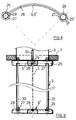
- FIG. 5 shows a sectional view along the section line B in FIG. 4, from which the structure of the hollow column 3 with an integrated light source 10 and loudspeaker 9 can be seen.
- This light source 10 can be one or more spotlights which emit onto the reflector placed on top. Since such light sources have a relatively high level of heat, a plurality of openings 16 are formed in the manner of a perforated plate at approximately the level of the second storage surface 8, so that good air circulation is achieved. If a loudspeaker 9 is arranged in a hanging position within the hollow column 3, these openings 16 serve for sound emission approximately at the level of the guests' ears.
- This perforated sheet metal ring can be formed by punching during the manufacture of the upper hollow column 3, the hollow column 3 having a height of approximately 2.40 m preferably being divided in the middle at the counter height, so that the counter surface 7 is inserted in between and by means of tie rods ( see Fig. 9) can be braced.
- FIG. 6 shows a side view of the pivoting door element 15, a hollow column 3 ′′ also being provided on the side, but here in a smaller diameter version.
- the pivoting door element 15 is connected to the stable end column 3 ′ via conventional door fittings (not shown).
- curved cladding elements 4 ' are also provided here, but here in a semicircular configuration, which are inserted into the upper and lower stabilizing strips 6, 6'.
- the swing door element 15 is preferably supported on support wheels 25, although the storage on conventional door fittings between the column 3 ′′ and the end column 3 ′ is sufficient to support the swing door element 15.
- the design with support wheels 25 has the advantage, however, that the pivoting door element 15 can be detached from the end pillar 3 'and can then serve as a freely movable mobile container, for example to pick up goods from a storage room or as a serving trolley.
- Fig. 7 the corresponding front view of the swing door element 15 is shown in training as a roll container, the relatively large storage spaces are visible.
- the two lateral hollow columns 3 '' can be used as a handle for pivoting or in the freely movable, loosened version as a roll container, so that safe handling of this showcase-like pivoting door element 15 is possible.
- the pivoting door element 15 shown here is also suitable for use in the living area as a display case or roll container, it also being possible to dispense with the upper part shown here as a frame for the monitor 21.
- such a furniture system thus consists of the basic module with the thin-walled cladding element 4 'and the tubular, supporting hollow column 3' ', this basic module being expanded by means of a further hollow column 3' '.
- Such a single piece of furniture can also be designed as a table or as a piece of seating furniture, with the integrated lights and / or loudspeakers at the upper end of the hollow column making it possible to provide optimal sound to the guest or visitor sitting on it.
- FIG. 8 shows a top view of the stabilization bar 6, 6 'shown schematically in FIGS. 4 and 5.
- the stabilizing bar extends over a pitch of 90 ° and has extensions 26 at both ends, on which the end faces of the hollow column 3 are inserted.
- the extension 26 is closed in the manner of a bearing eye executed so that this end is particularly suitable for inserting an end column 3 '.
- the extension 26 ends in the central plane of the inserted hollow column 3, a further stabilizing bar 6 with an extension 26 'joining one after the other.
- the stabilizing bar 6 also has a continuous guide groove 28 into which the horizontally running lower or upper edge of the cladding element 4 is inserted. It should be noted that through this guide groove 28 a curvature of the thin-walled cladding element is achieved in order to achieve the arched arch shape in adaptation to the particular desired furniture shape.
- the lining element 4 for example a thin metal plate, plastic plate or wooden plate, is to be stored with a smooth surface for transport, and is then only slightly bent during assembly and inserted into the guide groove 28.
- the corresponding plug connection results in addition to the insertion into the lower stabilization bar 6 'also by placing the corresponding upper stabilization bar 6, so that the cladding element, as described in connection with FIG. 1, is fixed on all sides, so as to provide the required stability.
- FIG. 9 shows an enlarged cross section through the end region of the lower stabilization bar 6 '. This shows in particular the plug connection with the cylindrical casing tube of the hollow column 3.
- tie rods or threaded rods 30 can be inserted, which can be screwed into the extensions 26 of the stabilizing bar 6 'with corresponding threaded or nut inserts 29. This results in a secure fixation between the preferably widened end faces of the hollow column 3 and the extensions 26 of the stabilizing bar 6 or 6 '.
- the upper stabilization bar 6 is then placed in a corresponding manner from above onto this hollow column 5 inserted into the lower stabilization bar 6, with these components being firmly clamped together with the covering element 4 due to the tie rods or threaded rods 30.
- the counter surface 7 placed on top can also be clamped downwards with the tie rods or screwed to the stabilizing bar 6 by means of a few fastening elements.
- an upper half of the hollow column is placed on the counter surface 7, such an attachment is not necessary since the storage or counter surface 7 can be clamped between the stacked halves of the hollow column 3.
- the tie rods or threaded rods 30 are preferably offset by 90 °, ie screwed crosswise, so that two threaded rods 30 are provided in the lower half of the hollow column, while two threaded rods 30 are also provided in the upper half of the hollow column, but rotated by 90 ° the threaded inserts 29 are screwed in.
- a central tie rod can also be provided.
- the swing door element 15 designed as a roll container can already form a small counter in connection with a single basic module 2 with two hollow columns 3, for example as an information stand at a trade fair or in a department store.
- the basic shape of the basic modules 2 for example a 45 ° element, 60 ° element or a 120 ° element instead of the 90 ° element shown here, there are a multitude of possible variations in the construction of the modular furniture system 1 possible.
- the swivel door element 15 designed as a roller container allows the counter or the sales stand formed in this way to be easily locked, if necessary in conjunction with roller shutters 13 integrated in the hollow columns 3.
- the proposed basic module 2 can also be used as a base element for Seating serve, for.
- the stringing shown in FIG. 2 can be designed as a bench that can be expanded as desired, with a padded seat back being attached to the adjacent hollow columns 3 instead of the counter surface 7.
Landscapes
- Engineering & Computer Science (AREA)
- Architecture (AREA)
- Civil Engineering (AREA)
- Structural Engineering (AREA)
- Assembled Shelves (AREA)
- Furniture Connections (AREA)
- Hydroponics (AREA)
- Floor Finish (AREA)
- Forms Removed On Construction Sites Or Auxiliary Members Thereof (AREA)
- Legs For Furniture In General (AREA)
Applications Claiming Priority (2)
| Application Number | Priority Date | Filing Date | Title |
|---|---|---|---|
| DE4436842 | 1994-10-14 | ||
| DE4436842A DE4436842C2 (de) | 1994-10-14 | 1994-10-14 | Modulares Möbelsystem |
Publications (3)
| Publication Number | Publication Date |
|---|---|
| EP0706771A2 true EP0706771A2 (fr) | 1996-04-17 |
| EP0706771A3 EP0706771A3 (fr) | 1999-05-12 |
| EP0706771B1 EP0706771B1 (fr) | 2002-05-08 |
Family
ID=6530829
Family Applications (1)
| Application Number | Title | Priority Date | Filing Date |
|---|---|---|---|
| EP95116116A Expired - Lifetime EP0706771B1 (fr) | 1994-10-14 | 1995-10-12 | Système modulaire de meubles |
Country Status (3)
| Country | Link |
|---|---|
| EP (1) | EP0706771B1 (fr) |
| AT (1) | ATE217164T1 (fr) |
| DE (2) | DE4436842C2 (fr) |
Cited By (2)
| Publication number | Priority date | Publication date | Assignee | Title |
|---|---|---|---|---|
| FR2906447A1 (fr) * | 2006-09-28 | 2008-04-04 | Armortech Sa | Ensemble modulaire de meubles |
| US9609944B2 (en) | 2015-02-20 | 2017-04-04 | Paul David Partywares LLC | Modular portable bar system |
Families Citing this family (5)
| Publication number | Priority date | Publication date | Assignee | Title |
|---|---|---|---|---|
| DE19621547A1 (de) | 1996-05-29 | 1997-12-04 | Schaerer Soehne Ag Usm U | Modulares Inneneinrichtungssystem |
| DE29804865U1 (de) * | 1998-03-13 | 1998-05-14 | KÜHLA Gastro-Technic GmbH, 49377 Vechta | Thekensystem |
| DE10032883B4 (de) * | 2000-07-06 | 2004-09-30 | Matthias Biehler | Vorrichtung zur Präsentation und/oder Ausgabe z. B. von Speisen und/oder Getränken und/oder zur Selbstbedienung an denselben |
| DE102013002673A1 (de) | 2013-02-12 | 2014-08-14 | Stefan Carl | Modulares Plattensystem zum variablen Aufbau von Einrichtungsgegenständen |
| DE202016106456U1 (de) * | 2016-11-17 | 2017-01-23 | Klagie Fahrzeubau e. K. | Bauwerkstand |
Citations (1)
| Publication number | Priority date | Publication date | Assignee | Title |
|---|---|---|---|---|
| EP0130354A2 (fr) | 1983-06-29 | 1985-01-09 | Theo Albert | Comptoir modulaire préfabriqué |
Family Cites Families (8)
| Publication number | Priority date | Publication date | Assignee | Title |
|---|---|---|---|---|
| NL91769C (fr) * | 1954-07-01 | |||
| US3835354A (en) * | 1972-09-06 | 1974-09-10 | Pena E Torres | Furniture and room partition components |
| US4417774A (en) * | 1981-06-25 | 1983-11-29 | Hastings, Clayton, Tucker & Craig, Inc. | Collapsible display booth |
| DE8224107U1 (de) * | 1982-08-26 | 1983-01-05 | Solida Textil- und Netzwaren-Manufaktur GmbH & Co KG, 3330 Helmstedt | Freistehende lager- oder verkaufswand |
| DE8800241U1 (de) * | 1988-01-12 | 1988-04-28 | Fugmann, Stephan | Flächiges Bauelement für eine Stellwand |
| DE8802246U1 (de) * | 1988-02-22 | 1988-04-07 | Werbeteam Ausstellungs- und Messebau GmbH + Co KG, 3300 Braunschweig | Doppelwandige Trennwand |
| DE9006147U1 (de) * | 1990-05-31 | 1991-09-26 | Gerd und Bernd Vieler KG, 5860 Iserlohn | Display-Gestell aus Rundprofil-Stangen und Eckverbindern zur Präsentation und zum Verkauf von Waren |
| DE4133635A1 (de) * | 1991-10-11 | 1993-04-15 | Hubert Bohner | Gastronomisches geraetesystem |
-
1994
- 1994-10-14 DE DE4436842A patent/DE4436842C2/de not_active Expired - Fee Related
-
1995
- 1995-10-12 AT AT95116116T patent/ATE217164T1/de not_active IP Right Cessation
- 1995-10-12 DE DE59510193T patent/DE59510193D1/de not_active Expired - Fee Related
- 1995-10-12 EP EP95116116A patent/EP0706771B1/fr not_active Expired - Lifetime
Patent Citations (1)
| Publication number | Priority date | Publication date | Assignee | Title |
|---|---|---|---|---|
| EP0130354A2 (fr) | 1983-06-29 | 1985-01-09 | Theo Albert | Comptoir modulaire préfabriqué |
Cited By (2)
| Publication number | Priority date | Publication date | Assignee | Title |
|---|---|---|---|---|
| FR2906447A1 (fr) * | 2006-09-28 | 2008-04-04 | Armortech Sa | Ensemble modulaire de meubles |
| US9609944B2 (en) | 2015-02-20 | 2017-04-04 | Paul David Partywares LLC | Modular portable bar system |
Also Published As
| Publication number | Publication date |
|---|---|
| EP0706771A3 (fr) | 1999-05-12 |
| EP0706771B1 (fr) | 2002-05-08 |
| DE59510193D1 (de) | 2002-06-13 |
| DE4436842A1 (de) | 1996-04-18 |
| ATE217164T1 (de) | 2002-05-15 |
| DE4436842C2 (de) | 1997-12-11 |
Similar Documents
| Publication | Publication Date | Title |
|---|---|---|
| EP0901332B1 (fr) | Systeme modulaire d'amenagement interieur | |
| DE2826336C2 (de) | Modulsystem zum Zusammensetzen von Wänden, Schränken, Schreibtischen und/oder anderen zerlegbaren Möbelstücken | |
| DE10297211T5 (de) | Modulares, verschiedenartig konfigurierbares Präsentationswandsystem | |
| EP0706771B1 (fr) | Système modulaire de meubles | |
| DE19854895A1 (de) | Gitter | |
| DE4219601C2 (de) | Verbindungssystem für Wandungsteile | |
| DE9404365U1 (de) | Möbelsystem | |
| DE3513000C2 (fr) | ||
| DE3641742C2 (fr) | ||
| DE9001020U1 (de) | Bausatz für einen überdachten Verkaufsstand, insbesondere zum Verkaufen von Brot- und Backwaren | |
| DE4023685C1 (en) | Support rail element for goods - has openings in rail sections to allow fitting of hooked brackets | |
| DE29516614U1 (de) | Paravent-Elementesystem | |
| DE9207974U1 (de) | Regalelement für die Aufnahme von CD's u.dgl. | |
| DE19847180C1 (de) | Säulenförmiges Profilelement zur Bildung eines Portals | |
| DE20010930U1 (de) | Möbelkorpus | |
| DE2611076A1 (de) | Buecherregal | |
| DE20312648U1 (de) | Profilstab für Raumgitter | |
| EP1369063A1 (fr) | Rayonnage de vente | |
| CH659874A5 (en) | Set of structural elements for producing a furniture-type object for fitting out a room | |
| DE29518622U1 (de) | Gestell, insbesondere Regalgestell | |
| DE19840973A1 (de) | Raumsystem | |
| DE9310743U1 (de) | Flexibles Tragwerk für Möbel | |
| AT503808A4 (de) | Modulares holzrahmensystem | |
| DE29815990U1 (de) | Regalsystem | |
| DE29700529U1 (de) | Kombinationsprofil |
Legal Events
| Date | Code | Title | Description |
|---|---|---|---|
| PUAI | Public reference made under article 153(3) epc to a published international application that has entered the european phase |
Free format text: ORIGINAL CODE: 0009012 |
|
| AK | Designated contracting states |
Kind code of ref document: A2 Designated state(s): AT CH DE DK FR GB IT LI SE |
|
| PUAL | Search report despatched |
Free format text: ORIGINAL CODE: 0009013 |
|
| AK | Designated contracting states |
Kind code of ref document: A3 Designated state(s): AT CH DE DK FR GB IT LI SE |
|
| 17P | Request for examination filed |
Effective date: 19991111 |
|
| 17Q | First examination report despatched |
Effective date: 20000629 |
|
| GRAG | Despatch of communication of intention to grant |
Free format text: ORIGINAL CODE: EPIDOS AGRA |
|
| GRAG | Despatch of communication of intention to grant |
Free format text: ORIGINAL CODE: EPIDOS AGRA |
|
| GRAH | Despatch of communication of intention to grant a patent |
Free format text: ORIGINAL CODE: EPIDOS IGRA |
|
| REG | Reference to a national code |
Ref country code: GB Ref legal event code: IF02 |
|
| GRAH | Despatch of communication of intention to grant a patent |
Free format text: ORIGINAL CODE: EPIDOS IGRA |
|
| GRAA | (expected) grant |
Free format text: ORIGINAL CODE: 0009210 |
|
| AK | Designated contracting states |
Kind code of ref document: B1 Designated state(s): AT CH DE DK FR GB IT LI SE |
|
| REF | Corresponds to: |
Ref document number: 217164 Country of ref document: AT Date of ref document: 20020515 Kind code of ref document: T |
|
| REG | Reference to a national code |
Ref country code: CH Ref legal event code: EP |
|
| REF | Corresponds to: |
Ref document number: 59510193 Country of ref document: DE Date of ref document: 20020613 |
|
| PG25 | Lapsed in a contracting state [announced via postgrant information from national office to epo] |
Ref country code: SE Free format text: LAPSE BECAUSE OF FAILURE TO SUBMIT A TRANSLATION OF THE DESCRIPTION OR TO PAY THE FEE WITHIN THE PRESCRIBED TIME-LIMIT Effective date: 20020808 Ref country code: DK Free format text: LAPSE BECAUSE OF FAILURE TO SUBMIT A TRANSLATION OF THE DESCRIPTION OR TO PAY THE FEE WITHIN THE PRESCRIBED TIME-LIMIT Effective date: 20020808 |
|
| GBT | Gb: translation of ep patent filed (gb section 77(6)(a)/1977) |
Effective date: 20020808 |
|
| ET | Fr: translation filed | ||
| PLBE | No opposition filed within time limit |
Free format text: ORIGINAL CODE: 0009261 |
|
| STAA | Information on the status of an ep patent application or granted ep patent |
Free format text: STATUS: NO OPPOSITION FILED WITHIN TIME LIMIT |
|
| 26N | No opposition filed |
Effective date: 20030211 |
|
| PGFP | Annual fee paid to national office [announced via postgrant information from national office to epo] |
Ref country code: GB Payment date: 20031016 Year of fee payment: 9 |
|
| PG25 | Lapsed in a contracting state [announced via postgrant information from national office to epo] |
Ref country code: GB Free format text: LAPSE BECAUSE OF NON-PAYMENT OF DUE FEES Effective date: 20041012 |
|
| GBPC | Gb: european patent ceased through non-payment of renewal fee |
Effective date: 20041012 |
|
| PGFP | Annual fee paid to national office [announced via postgrant information from national office to epo] |
Ref country code: FR Payment date: 20051024 Year of fee payment: 11 |
|
| PGFP | Annual fee paid to national office [announced via postgrant information from national office to epo] |
Ref country code: AT Payment date: 20051027 Year of fee payment: 11 |
|
| PGFP | Annual fee paid to national office [announced via postgrant information from national office to epo] |
Ref country code: CH Payment date: 20051123 Year of fee payment: 11 |
|
| PG25 | Lapsed in a contracting state [announced via postgrant information from national office to epo] |
Ref country code: AT Free format text: LAPSE BECAUSE OF NON-PAYMENT OF DUE FEES Effective date: 20061012 |
|
| PG25 | Lapsed in a contracting state [announced via postgrant information from national office to epo] |
Ref country code: LI Free format text: LAPSE BECAUSE OF NON-PAYMENT OF DUE FEES Effective date: 20061031 Ref country code: CH Free format text: LAPSE BECAUSE OF NON-PAYMENT OF DUE FEES Effective date: 20061031 |
|
| PGFP | Annual fee paid to national office [announced via postgrant information from national office to epo] |
Ref country code: IT Payment date: 20061031 Year of fee payment: 12 |
|
| PGFP | Annual fee paid to national office [announced via postgrant information from national office to epo] |
Ref country code: DE Payment date: 20070430 Year of fee payment: 12 |
|
| REG | Reference to a national code |
Ref country code: CH Ref legal event code: PL |
|
| REG | Reference to a national code |
Ref country code: FR Ref legal event code: ST Effective date: 20070629 |
|
| PG25 | Lapsed in a contracting state [announced via postgrant information from national office to epo] |
Ref country code: FR Free format text: LAPSE BECAUSE OF NON-PAYMENT OF DUE FEES Effective date: 20061031 |
|
| PG25 | Lapsed in a contracting state [announced via postgrant information from national office to epo] |
Ref country code: DE Free format text: LAPSE BECAUSE OF NON-PAYMENT OF DUE FEES Effective date: 20080501 |
|
| PG25 | Lapsed in a contracting state [announced via postgrant information from national office to epo] |
Ref country code: IT Free format text: LAPSE BECAUSE OF NON-PAYMENT OF DUE FEES Effective date: 20071012 |