EP0706835A1 - Méthode de mise en oeuvre d'un transducteur ultrasonique, piezoélectrique et circuit destiné à sa mise en application - Google Patents
Méthode de mise en oeuvre d'un transducteur ultrasonique, piezoélectrique et circuit destiné à sa mise en application Download PDFInfo
- Publication number
- EP0706835A1 EP0706835A1 EP94115958A EP94115958A EP0706835A1 EP 0706835 A1 EP0706835 A1 EP 0706835A1 EP 94115958 A EP94115958 A EP 94115958A EP 94115958 A EP94115958 A EP 94115958A EP 0706835 A1 EP0706835 A1 EP 0706835A1
- Authority
- EP
- European Patent Office
- Prior art keywords
- electrodes
- reception
- mode
- transmission
- receiving mode
- Prior art date
- Legal status (The legal status is an assumption and is not a legal conclusion. Google has not performed a legal analysis and makes no representation as to the accuracy of the status listed.)
- Granted
Links
Images


Classifications
-
- B—PERFORMING OPERATIONS; TRANSPORTING
- B06—GENERATING OR TRANSMITTING MECHANICAL VIBRATIONS IN GENERAL
- B06B—METHODS OR APPARATUS FOR GENERATING OR TRANSMITTING MECHANICAL VIBRATIONS OF INFRASONIC, SONIC, OR ULTRASONIC FREQUENCY, e.g. FOR PERFORMING MECHANICAL WORK IN GENERAL
- B06B1/00—Methods or apparatus for generating mechanical vibrations of infrasonic, sonic, or ultrasonic frequency
- B06B1/02—Methods or apparatus for generating mechanical vibrations of infrasonic, sonic, or ultrasonic frequency making use of electrical energy
- B06B1/06—Methods or apparatus for generating mechanical vibrations of infrasonic, sonic, or ultrasonic frequency making use of electrical energy operating with piezoelectric effect or with electrostriction
- B06B1/0644—Methods or apparatus for generating mechanical vibrations of infrasonic, sonic, or ultrasonic frequency making use of electrical energy operating with piezoelectric effect or with electrostriction using a single piezoelectric element
- B06B1/0662—Methods or apparatus for generating mechanical vibrations of infrasonic, sonic, or ultrasonic frequency making use of electrical energy operating with piezoelectric effect or with electrostriction using a single piezoelectric element with an electrode on the sensitive surface
-
- B—PERFORMING OPERATIONS; TRANSPORTING
- B06—GENERATING OR TRANSMITTING MECHANICAL VIBRATIONS IN GENERAL
- B06B—METHODS OR APPARATUS FOR GENERATING OR TRANSMITTING MECHANICAL VIBRATIONS OF INFRASONIC, SONIC, OR ULTRASONIC FREQUENCY, e.g. FOR PERFORMING MECHANICAL WORK IN GENERAL
- B06B1/00—Methods or apparatus for generating mechanical vibrations of infrasonic, sonic, or ultrasonic frequency
- B06B1/02—Methods or apparatus for generating mechanical vibrations of infrasonic, sonic, or ultrasonic frequency making use of electrical energy
- B06B1/0207—Driving circuits
-
- B—PERFORMING OPERATIONS; TRANSPORTING
- B06—GENERATING OR TRANSMITTING MECHANICAL VIBRATIONS IN GENERAL
- B06B—METHODS OR APPARATUS FOR GENERATING OR TRANSMITTING MECHANICAL VIBRATIONS OF INFRASONIC, SONIC, OR ULTRASONIC FREQUENCY, e.g. FOR PERFORMING MECHANICAL WORK IN GENERAL
- B06B1/00—Methods or apparatus for generating mechanical vibrations of infrasonic, sonic, or ultrasonic frequency
- B06B1/02—Methods or apparatus for generating mechanical vibrations of infrasonic, sonic, or ultrasonic frequency making use of electrical energy
- B06B1/06—Methods or apparatus for generating mechanical vibrations of infrasonic, sonic, or ultrasonic frequency making use of electrical energy operating with piezoelectric effect or with electrostriction
- B06B1/0688—Methods or apparatus for generating mechanical vibrations of infrasonic, sonic, or ultrasonic frequency making use of electrical energy operating with piezoelectric effect or with electrostriction with foil-type piezoelectric elements, e.g. PVDF
- B06B1/0692—Methods or apparatus for generating mechanical vibrations of infrasonic, sonic, or ultrasonic frequency making use of electrical energy operating with piezoelectric effect or with electrostriction with foil-type piezoelectric elements, e.g. PVDF with a continuous electrode on one side and a plurality of electrodes on the other side
-
- H—ELECTRICITY
- H03—ELECTRONIC CIRCUITRY
- H03H—IMPEDANCE NETWORKS, e.g. RESONANT CIRCUITS; RESONATORS
- H03H9/00—Networks comprising electromechanical or electro-acoustic elements; Electromechanical resonators
- H03H9/02—Details
- H03H9/125—Driving means, e.g. electrodes, coils
- H03H9/13—Driving means, e.g. electrodes, coils for networks consisting of piezoelectric or electrostrictive materials
- H03H9/132—Driving means, e.g. electrodes, coils for networks consisting of piezoelectric or electrostrictive materials characterized by a particular shape
-
- H—ELECTRICITY
- H03—ELECTRONIC CIRCUITRY
- H03H—IMPEDANCE NETWORKS, e.g. RESONANT CIRCUITS; RESONATORS
- H03H9/00—Networks comprising electromechanical or electro-acoustic elements; Electromechanical resonators
- H03H9/46—Filters
- H03H9/54—Filters comprising resonators of piezoelectric or electrostrictive material
- H03H9/545—Filters comprising resonators of piezoelectric or electrostrictive material including active elements
Definitions
- the invention relates to a method of operating an ultrasonic piezoelectric transducer alternatingly in a transmitting mode and in a receiving mode, the transducer comprising a body of piezoelectric material provided with at least three electrodes, wherein in the transmitting mode an electrical excitation signal is applied between one or more common electrodes and one or more transmission electrodes adapted to excite the body of piezoelectric material to mechanical vibrations in a radial, thickness or overtones vibration mode, and wherein in the receiving mode an electrical reception signal is collected between the one or more common electrodes and one or more reception electrodes adapted to convert mechanical vibrations of the body of piezoelectric material into an electrical signal.
- the invention further relates to a circuit arrangement for performing the method.
- the normal piezoelectric elements which are used in ultrasonic sensors possess a series resonance frequency and a parallel resonance frequency. It is well known that these elements show the maximum displacement and thus the optimum transmission performance at the series resonance frequency, but the maximum receiving sensitivity at the parallel resonance frequency which is up to 16% higher than the series resonance frequency.
- an ultrasonic piezoelectric transducer is operated at its series resonance frequency so that it emits ultrasonic waves with maximum efficiency, it can receive the echo signals, which have the same frequency, only with a poor sensitivity. This is the reason why in many cases two piezoelectric sensors are used, one for transmission which is so designed that its series resonance frequency coincides with the operating frequency, and the other one for reception which is so designed that its parallel resonance frequency coincides with the operating frequency.
- this object is achieved in a method as defined at the beginning in that in the receiving mode one or more electrodes which are not used as reception electrodes are connected via a low impedance connection with the one or more common electrodes.
- the method according to the invention has the effect that in the receiving mode the resonance frequencies of the piezoelectric transducer are shifted to lower values so that the parallel resonance frequency assumes the frequency value which the series resonance frequency has in the transmitting mode.
- the piezoelectric transducer is in series resonance in the transmitting mode and in parallel resonance in the receiving mode. In this way, the piezoelectric transducer operates under optimum conditions with perfect frequency matching both for transmission and for reception.
- a circuit arrangement for performing the method as defined above comprises an ultrasonic piezoelectric transducer having a body of piezoelectric material provided with at least three electrodes, an excitation signal source adapted to be connected to one or more common electrodes and one or more electrodes which are used as transmission electrodes in a transmitting mode, and a reception circuit adapted to be connected to the one or more common electrodes and one or more electrodes which are used as reception electrodes in a receiving mode.
- this circuit arrangement is characterized by means for establishing a low impedance connection in the receiving mode between the one or more common electrodes and one or more electrodes which are not used as reception electrodes.
- the circuit arrangement shown in Fig. 1 comprises an ultrasonic piezoelectric transducer 10 having a body 11 of piezoelectric material, which in the illustrated embodiment is in the form of a circular disk, and electrodes 12, 13 and 14 formed by metallizations or metal layers applied to opposite sides of the body 11.
- the electrode 12 is a common electrode applied to a first side of the body 11 which in Fig. 1 is the bottom side of the disk, and the two electrodes 13 and 14 are applied to an opposite second side of the body 11 which in Fig. 1 is the top side of the disk.
- the electrode 13 is a circular central electrode
- the electrode 14 is an annular electrode surrounding the central electrode 13, the two electrodes being separated and electrically isolated from each other by an annular gap 15.
- the common electrode 12 is connected to a common potential, for instance the ground potential
- the annular electrode 14 is connected with the output of an excitation signal source 20 via a switch 21
- the central electrode 13 is adapted to be connected with the input of a reception circuit 22 via a switch 23.
- This arrangement permits to operate the piezoelectric transducer 10 alternatingly in a transmitting mode and in a receiving mode.
- the switch 21 is closed and the switch 23 is open which is the position shown in Fig. 1.
- the excitation signal source 20 emits an alternating electrical excitation signal which is applied to the piezoelectric transducer 10 between the common electrode 12 and the annular electrode 14.
- This alternating electrical excitation signal causes the piezoelectric transducer 10 to vibrate in a radial, thickness or overtones vibration mode and to emit an ultrasonic wave having the frequency of the alternating electrical excitation signal.
- the position of the switches 21 and 23 are reversed so that the switch 21 is open and the switch 23 is closed.
- No electrical excitation signal is applied to the piezoelectric transducer 10; when the piezoelectric transducer 10 is set into vibrations by arriving ultrasonic waves, it generates an alternating electrical reception signal having the frequency of the ultrasonic wave between the common electrode 12 and the central electrode 13. This reception signal is applied to the input of the reception circuit 22.
- the excitation signal source 20 supplies short transmission pulses in regularly spaced transmission periods to the piezoelectric transducer 10 which for each transmission pulse emits a pulse-shaped ultrasonic wave which is propagated through the medium surrounding the piezoelectric transducer 10.
- the interval between two consecutive transmission pulses is a reception period in which the piezoelectric transducer 10 receives ultrasonic echo pulses generated by reflection of the ultrasonic waves at targets situated in the path of propagation.
- These ultrasonic echo pulses are converted by the piezoelectric transducer 10 into electrical reception signals that are supplied to the reception circuit 22.
- the time which elapsed between the transmission of a transmission pulse and the receipt of an echo pulse corresponds to the transit time of the ultrasonic wave from the piezoelectric transducer 10 to the target and back to the piezoelectric transducer 10, and from this transit time and the known sonic speed in the propagation medium the distance between the piezoelectric transducer 10 and the target can be calculated.
- the propagation medium usually is air or water, as for instance in echo sounding or sonar applications.
- Other fields of use in which the same ultrasonic piezoelectric transducer is alternatingly operated in a transmitting mode and in a receiving mode with other propagation media are medical ultrasonic devices, non-destructive testing of materials, ultrasonic delay lines and piezoelectric bulk filters.
- the diagram A of Fig. 3 shows the impedance versus frequency characteristic curve of an ultrasonic piezoelectric transducer of this type.
- the impedance Z has a minimum value at a frequency f RS which is the series resonance frequency, and a maximum value at a frequency f RP which is the parallel resonance frequency.
- the parallel resonance frequency f RP is about 16% higher than the series resonance frequency f RS .
- the piezoelectric transducers show the maximum displacement at the series resonance frequency f RS , as apparent from the diagram B in Fig.
- the ultrasound pressure P has a maximum value at the series resonance frequency f RS and a much lower value at the parallel resonance frequency f RP .
- the piezoelectric transducers have the maximum receiving sensitivity at the parallel resonance frequency f RP as visible in the diagram C of Fig. 3 which shows the characteristic curve of the sensitivity S versus the frequency f; the sensitivity S has a maximum value at the parallel resonance frequency f RP and a much lower value at the series resonance frequency f RS .
- the optimum conditions prevail when the operating frequency is equal to the series resonance frequency f RS , and for purposes of reception the optimum conditions prevail when the operating frequency is equal to the parallel resonance frequency f RP .
- the operating frequency is the same in the transmitting mode and in the receiving mode, viz the frequency of the electrical excitation signal applied to the transmission electrode in the transmitting mode.
- the circuit arrangement has the configuration shown in Fig. 4.
- the switch 21 is open so that the annular electrode 14 is disconnected from the excitation signal source 20, and the switch 23 is closed so that the central electrode 13 is connected with the input of the reception circuit 22. Moreover, the switch 24 is closed so that the annular electrode 14 is short-circuited to the common electrode 12.
- the short-circuiting of the annular electrode 14 has the effect that the series and parallel resonance frequencies of the piezoelectric transducer are shifted to lower values, as shown by the diagram D of Fig. 3.
- Diagram D shows the impedance versus frequency characteristic curve of the same piezoelectric transducer as in the case of diagram A, but with the annular electrode 14 being short-circuited to the common electrode 12.
- the parallel resonance frequency f RP has the same value as the series resonance frequency f RS had in diagram A without the short-circuit.
- the same operating frequency f O is equal to the series resonance frequency f RS in the transmitting mode and equal to the parallel resonance frequency f RP in the receiving mode.
- the sensitivity S has the maximum value at the operating frequency f O , as apparent from the diagram E of Fig. 3. In this way, optimum conditions are obtained both for transmission and for reception with a single piezoelectric transducer.
- the switches 21, 23 and 24 are represented in Figs. 1 and 4 by the symbols of mechanical switches in order to illustrate the function of these switches more clearly; in reality these switches, if they exist, will normally be fast electronic switches, such as field effect transistors.
- the electrical impedance between the reception electrode 13 and the common electrode 12 in the transmitting mode is higher than the electrical impedance which exists between the reception electrode 13 and the common electrode 12 at the parallel resonance frequency f RP of the piezoelectric transducer 10 in the receiving mode.
- the switches 21 and 24 can be omitted if the output impedance of the excitation signal source 20 is very small, in which case there will be a low impedance connection between the transmission electrode 14 and the common electrode 12 via the small output impedance of the excitation signal source 20 in the receiving mode; and the switch 23 can be omitted if the input impedance of the reception circuit 22 is high enough, in which case there will be a high impedance connection between the reception electrode 13 and the common electrode 12 via the large input impedance of the reception circuit 22 in the transmission mode.
- FIG. 5 A circuit arrangement which meets the foregoing requirements and therefore does not require the use of switches performing the functions of the switches 21, 23 and 24 in Figs. 1 and 4 is shown in Fig. 5.
- the circuit arrangement of Fig. 5 again comprises the ultrasonic piezoelectric transducer 10 having the piezoelectric body 11 and the electrodes 12, 13 and 14.
- Fig. 5 further shows a CMOS output circuit 30 of the excitation signal source 20, which CMOS output circuit comprises two CMOS field effect transistors 31, 32 connected in series via their sources and drains between a supply voltage +E and ground.
- CMOS output circuit 30 has a very low output impedance which in the receiving mode essentially provides a short-circuit connection between the electrodes 14 and 12.
- Fig. 5 shows an input amplifier stage 40 of the reception circuit 22, which input amplifier stage comprises a MOSFET 41 having a drain connected to the supply voltage +E via a resistor 42, a source connected to ground and a gate connected to ground via a high resistance gate resistor 43.
- the electrode 13 is permanently connected with the input terminal 44 of this input amplifier stage, which is the gate electrode of the MOSFET 41, while the output terminal 45 is the connection between the source and the resistor 42.
- This input amplifier stage 40 has a high input impedance which in the transmitting mode essentially isolates the electrode 13 from the common electrode 12.
- the piezoelectric transducer 10 has the impedance versus frequency characteristic curve shown in diagram A of Fig. 3, since the reception electrode 13 is essentially isolated from the common electrode 12 due to the high input impedance of the input amplifier stage 40; and when the circuit arrangement of Fig.
- the piezoelectric transducer 10 operates in the receiving mode, the piezoelectric transducer 10 has the impedance versus frequency characteristic curve shown in diagram D of Fig. 3, since the electrode 14 is essentially short-circuited to the common electrode 12 by the low output impedance of the CMOS output stage 30. Accordingly, the circuit arrangement of Fig. 5 provides the same optimum conditions both for transmission and for reception with a single piezoelectric transducer as the circuit arrangement of Fig. 1, but without any switches.
- the ultrasonic piezoelectric transducer can be provided with more than three electrodes which can be electrically interconnected so that there are two or more common electrodes and/or two or more transmission electrodes and/or two or more reception elctrodes.
- FIG. 6 shows an ultrasonic piezoelectric transducer 50 having a body 51 of piezoelectric material in the form of a circular disk, an electrode 52 covering the bottom side of the body 51, and three electrodes 53, 54, 55 applied to the top side of the body 11.
- the electrode 53 is a circular central electrode which is surrounded by the two annular electrodes 54 and 55.
- This transducer can be operated in any one of the following modifications:
- the commutated electrodes are the transmission electrodes. This, however, is not imperative. It was found that the desired shifting of the resonant frequencies is always obtained if the capacitance measured between the one or more commutated electrodes and the one or more common electrodes in the transmitting mode is equal to the capacitance measured between the one or more transmission electrodes and the one or more common electrodes.
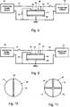
- the circuit arrangement shown in Figs. 8 and 9 is similar to the embodiment of Fig. 1 in that it comprises an excitation signal source 20, a reception circuit 22 and switches 21, 23 and 24 which have the same functions as the corresponding parts in Fig. 1 and therefore are designated with the same reference numerals.
- the circuit arrangement of Figs. 8 and 9 further comprises an ultrasonic piezoelectric transducer 60 having a body 61 of piezoelectric material, a common electrode 62 applied to the bottom side of the body 61, and two electrodes 63 and 64 applied to the top side of the body 61.
- the electrodes 63 and 64 have identical semicircular shapes and are separated and electrically isolated from each other by a diametrical gap 65.
- the transducer 60 of Fig. 8 differs from the transducer 10 of Fig. 1 only with respect to the shape of the top electrodes.
- a further difference between the embodiments of Figures 1 and 8 resides in the manner in which the top electrodes are adapted to be connected with the excitation signal source 20 and the reception circuit 22, respectively.
- the same electrode 64 is adapted to be connected with the output of the excitation signal source 20 via the switch 21 and with the input of the reception circuit 22 via the switch 23, whereas the other electrode 63 is adapted to be short-circuited to the common electrode 62 via the switch 24.
- Fig. 8 shows the configuration of the circuit arrangement in the transmitting mode, in which the switch 21 is closed and the switches 23 and 24 are open.
- the electrode 64 is connected with the output of the excitation signal source 20 so that it functions as transmission electrode, and at the same time it is disconnected from the input of the reception circuit 22.
- the other electrode 63 is floating and isolated from the common electrode 62.
- Fig. 9 shows the configuration of the same circuit arrangement in the receiving mode, in which the positions of the switches are reversed so that the switch 21 is open and the switches 23 and 24 are closed.
- the electrode 64 is disconnected from the output of the excitation signal source 20 and connected with the input of the reception circuit 22 so that it functions as reception electrode.
- the other electrode 63 is now short-circuited to the common electrode 62 by the switch 24.
- the transmission electrode 64 is used as the reception electrode in the receiving mode and therefore cannot be short-circuited to the common electrode, the desired matching of the resonance frequencies is again obtained because in the receiving mode a short-circuit is established between the electrode 63 and the common electrode 62. Due to the identical size and shape of the electrodes 63 and 64, the capacitance measured between the electrode 63 and the common electrode 62 when there is no short-circuit (i.e. in the transmitting mode) is equal to the capacitance measured between the transmission electrode 64 and the common electrode 62. Owing to this identical capacitance, the short-circuiting of the electrode 63 in the receiving mode has the same effect as if the transmission electrode 64 itself was short-circuited.
- Fig. 11 shows the top view of a piezoelectric transducer 70 having four electrodes 71, 72, 73, 74 of quadrant-shape applied to its top side opposite to a common electrode (not shown) which isapplied to its bottom side. Since all electrodes 71, 72, 73 and 74 are of the same size and shape, they have the same capacitance with respect to the common electrode. It would, therefore, be possible to use these electrodes in different combinations as transmission and/or reception electrodes and to replace one or more of the transmission electrodes by other electrodes in establishing the low impedance connections with the common electrode in the receiving mode.
- the frequency matching obtained by the measures described above is not limited to transducers having circular disk-shaped bodies, but can be obtained with piezoelectric elements of any arbitrary configuration vibrating in a radial, thickness or overtones vibration mode.
Landscapes
- Engineering & Computer Science (AREA)
- Mechanical Engineering (AREA)
- Physics & Mathematics (AREA)
- Acoustics & Sound (AREA)
- Transducers For Ultrasonic Waves (AREA)
- Ultra Sonic Daignosis Equipment (AREA)
- Measurement Of Velocity Or Position Using Acoustic Or Ultrasonic Waves (AREA)
Priority Applications (5)
| Application Number | Priority Date | Filing Date | Title |
|---|---|---|---|
| DE69416129T DE69416129T2 (de) | 1994-10-10 | 1994-10-10 | Ein Verfahren zum Betrieb eines Ultraschallwandlers und Schaltungsanordnung zur Durchführung des Verfahrens |
| EP94115958A EP0706835B1 (fr) | 1994-10-10 | 1994-10-10 | Méthode de mise en oeuvre d'un transducteur ultrasonique piezoélectrique et circuit destiné à sa mise en application |
| CA002157652A CA2157652C (fr) | 1994-10-10 | 1995-09-06 | Methode et circuit d'utilisation de transducteurs piezoelectriques a ultrasons |
| JP7263050A JP2760963B2 (ja) | 1994-10-10 | 1995-10-11 | 圧電形超音波トランスデューサの作動方法及び該方法を実施するための回路装置 |
| US08/906,130 US5757104A (en) | 1994-10-10 | 1997-08-05 | Method of operating an ultransonic piezoelectric transducer and circuit arrangement for performing the method |
Applications Claiming Priority (1)
| Application Number | Priority Date | Filing Date | Title |
|---|---|---|---|
| EP94115958A EP0706835B1 (fr) | 1994-10-10 | 1994-10-10 | Méthode de mise en oeuvre d'un transducteur ultrasonique piezoélectrique et circuit destiné à sa mise en application |
Publications (2)
| Publication Number | Publication Date |
|---|---|
| EP0706835A1 true EP0706835A1 (fr) | 1996-04-17 |
| EP0706835B1 EP0706835B1 (fr) | 1999-01-20 |
Family
ID=8216373
Family Applications (1)
| Application Number | Title | Priority Date | Filing Date |
|---|---|---|---|
| EP94115958A Expired - Lifetime EP0706835B1 (fr) | 1994-10-10 | 1994-10-10 | Méthode de mise en oeuvre d'un transducteur ultrasonique piezoélectrique et circuit destiné à sa mise en application |
Country Status (5)
| Country | Link |
|---|---|
| US (1) | US5757104A (fr) |
| EP (1) | EP0706835B1 (fr) |
| JP (1) | JP2760963B2 (fr) |
| CA (1) | CA2157652C (fr) |
| DE (1) | DE69416129T2 (fr) |
Cited By (3)
| Publication number | Priority date | Publication date | Assignee | Title |
|---|---|---|---|---|
| EP3360617A1 (fr) * | 2017-02-10 | 2018-08-15 | Kabushiki Kaisha Toshiba | Transducteur et réseau de transducteur |
| EP3576429A4 (fr) * | 2017-01-25 | 2020-11-18 | Murata Manufacturing Co., Ltd. | Dispositif ultrasonore |
| WO2024056273A1 (fr) | 2022-09-14 | 2024-03-21 | Tdk Electronics Ag | Composant transducteur |
Families Citing this family (63)
| Publication number | Priority date | Publication date | Assignee | Title |
|---|---|---|---|---|
| EP0839585A3 (fr) * | 1996-10-31 | 2000-12-27 | Eastman Kodak Company | Procédé et dispositif pour l'épreuve d'un dispositif pour l'élimination des bulles au moyen d'un combinaison transducteur-horne |
| US6138507A (en) * | 1997-04-30 | 2000-10-31 | Endress + Hauser Gmbh + Co. | Apparatus for establishing and/or monitoring a predetermined filling level in a container through controlled transducer phase and impedance |
| US5939815A (en) * | 1997-07-23 | 1999-08-17 | The United States Of America As Represented By The Secretary Of The Army | Field trapping electrodes |
| US6196059B1 (en) * | 1997-08-11 | 2001-03-06 | Fraunhofer Gesellschaft Zur Forderung Der Angewandten Forschung E.V. | Piezoelectric resonator, process for the fabrication thereof including its use as a sensor element for the determination of the concentration of a substance contained in a liquid and/or for the determination of the physical properties of the liquid |
| US6140740A (en) * | 1997-12-30 | 2000-10-31 | Remon Medical Technologies, Ltd. | Piezoelectric transducer |
| US20030036746A1 (en) | 2001-08-16 | 2003-02-20 | Avi Penner | Devices for intrabody delivery of molecules and systems and methods utilizing same |
| DE69933663D1 (de) * | 1999-08-03 | 2006-11-30 | Eta Sa Mft Horlogere Suisse | Elektronischer Wandler eines akustischen Signals in ein pseudo-digitales Signal und bidirektionelles Kommunikationsverfahren durch Schallwellen |
| SG97904A1 (en) * | 1999-08-04 | 2003-08-20 | Ebauchesfabrik Eta Ag | Electronic converter for converting an acoustic signal into a pseudodigital signal, timepiece including such a converter and two-directional communications method via acoustic waves |
| JP3478230B2 (ja) * | 2000-03-21 | 2003-12-15 | 株式会社村田製作所 | 圧電トランスの特性選別方法 |
| KR100349126B1 (ko) * | 2000-05-04 | 2002-08-17 | 삼성전기주식회사 | 형광등용 압전트랜스포머 |
| US7024248B2 (en) * | 2000-10-16 | 2006-04-04 | Remon Medical Technologies Ltd | Systems and methods for communicating with implantable devices |
| US6764446B2 (en) | 2000-10-16 | 2004-07-20 | Remon Medical Technologies Ltd | Implantable pressure sensors and methods for making and using them |
| US7283874B2 (en) | 2000-10-16 | 2007-10-16 | Remon Medical Technologies Ltd. | Acoustically powered implantable stimulating device |
| US6731437B2 (en) * | 2001-05-04 | 2004-05-04 | Applera Corporation | Energy beam guide for an electrophoresis system |
| JP3944052B2 (ja) * | 2001-12-27 | 2007-07-11 | 株式会社デンソー | 超音波送受波器及びこれを用いた超音波クリアランスソナー |
| US7610092B2 (en) * | 2004-12-21 | 2009-10-27 | Ebr Systems, Inc. | Leadless tissue stimulation systems and methods |
| US7765001B2 (en) * | 2005-08-31 | 2010-07-27 | Ebr Systems, Inc. | Methods and systems for heart failure prevention and treatments using ultrasound and leadless implantable devices |
| JP5121011B2 (ja) * | 2004-11-24 | 2013-01-16 | レモン メディカル テクノロジーズ リミテッド | 音響トランスデューサを組み込んだインプラント可能な医療機器 |
| US7522962B1 (en) | 2004-12-03 | 2009-04-21 | Remon Medical Technologies, Ltd | Implantable medical device with integrated acoustic transducer |
| US7606621B2 (en) * | 2004-12-21 | 2009-10-20 | Ebr Systems, Inc. | Implantable transducer devices |
| US7558631B2 (en) * | 2004-12-21 | 2009-07-07 | Ebr Systems, Inc. | Leadless tissue stimulation systems and methods |
| JP4904704B2 (ja) * | 2005-03-18 | 2012-03-28 | アイシン精機株式会社 | 荷重検知装置 |
| DE102005024134A1 (de) | 2005-05-23 | 2007-01-11 | Endress + Hauser Flowtec Ag | Verfahren zur Bestimmung und/oder Überwachung einer Prozessgröße |
| US7570998B2 (en) * | 2005-08-26 | 2009-08-04 | Cardiac Pacemakers, Inc. | Acoustic communication transducer in implantable medical device header |
| US7615012B2 (en) * | 2005-08-26 | 2009-11-10 | Cardiac Pacemakers, Inc. | Broadband acoustic sensor for an implantable medical device |
| US7702392B2 (en) | 2005-09-12 | 2010-04-20 | Ebr Systems, Inc. | Methods and apparatus for determining cardiac stimulation sites using hemodynamic data |
| US8078278B2 (en) * | 2006-01-10 | 2011-12-13 | Remon Medical Technologies Ltd. | Body attachable unit in wireless communication with implantable devices |
| US7650185B2 (en) * | 2006-04-25 | 2010-01-19 | Cardiac Pacemakers, Inc. | System and method for walking an implantable medical device from a sleep state |
| US7912548B2 (en) * | 2006-07-21 | 2011-03-22 | Cardiac Pacemakers, Inc. | Resonant structures for implantable devices |
| JP2009544366A (ja) * | 2006-07-21 | 2009-12-17 | カーディアック ペースメイカーズ, インコーポレイテッド | 金属製キャビティが植え込まれた医療器具に用いる超音波トランスデューサ |
| US7986198B2 (en) * | 2006-08-03 | 2011-07-26 | Panasonic Corporation | Frequency-variable acoustic thin film resonator, filter and communication apparatus using the same |
| JP5274803B2 (ja) * | 2006-09-27 | 2013-08-28 | シチズンホールディングス株式会社 | 発振装置、および振動ジャイロ |
| WO2008054395A1 (fr) * | 2006-11-03 | 2008-05-08 | Research Triangle Institute | Sondes d'imagerie à ultrasons améliorées utilisant des transducteurs piézoélectriques en mode courbure |
| US20080171941A1 (en) * | 2007-01-12 | 2008-07-17 | Huelskamp Paul J | Low power methods for pressure waveform signal sampling using implantable medical devices |
| JP5231525B2 (ja) * | 2007-03-26 | 2013-07-10 | レモン メディカル テクノロジーズ, リミテッド | 埋込型医療デバイスのためのバイアスされた音響スイッチ |
| US8825161B1 (en) | 2007-05-17 | 2014-09-02 | Cardiac Pacemakers, Inc. | Acoustic transducer for an implantable medical device |
| US8718773B2 (en) | 2007-05-23 | 2014-05-06 | Ebr Systems, Inc. | Optimizing energy transmission in a leadless tissue stimulation system |
| EP2162185B1 (fr) * | 2007-06-14 | 2015-07-01 | Cardiac Pacemakers, Inc. | Système de recharge acoustique à plusieurs éléments |
| US7953493B2 (en) | 2007-12-27 | 2011-05-31 | Ebr Systems, Inc. | Optimizing size of implantable medical devices by isolating the power source |
| WO2009120636A1 (fr) | 2008-03-25 | 2009-10-01 | Ebr Systems, Inc. | Connexion d’électrode temporaire pour des systèmes de stimulation sans fil |
| US8078285B2 (en) * | 2008-03-28 | 2011-12-13 | Medtronic, Inc. | Reversible implantable acoustic sensor |
| US20090312650A1 (en) * | 2008-06-12 | 2009-12-17 | Cardiac Pacemakers, Inc. | Implantable pressure sensor with automatic measurement and storage capabilities |
| US8798761B2 (en) * | 2008-06-27 | 2014-08-05 | Cardiac Pacemakers, Inc. | Systems and methods of monitoring the acoustic coupling of medical devices |
| US20100016911A1 (en) | 2008-07-16 | 2010-01-21 | Ebr Systems, Inc. | Local Lead To Improve Energy Efficiency In Implantable Wireless Acoustic Stimulators |
| US20100023091A1 (en) * | 2008-07-24 | 2010-01-28 | Stahmann Jeffrey E | Acoustic communication of implantable device status |
| US8593107B2 (en) * | 2008-10-27 | 2013-11-26 | Cardiac Pacemakers, Inc. | Methods and systems for recharging an implanted device by delivering a section of a charging device adjacent the implanted device within a body |
| JP5195587B2 (ja) * | 2009-03-31 | 2013-05-08 | 株式会社デンソー | 超音波センサ |
| TWI422081B (zh) | 2010-09-24 | 2014-01-01 | China Steel Corp | Piezoelectric ceramic chip resonator and its making method |
| US8395301B1 (en) * | 2010-12-08 | 2013-03-12 | The United States Of America As Represented By The Secretary Of The Navy | High power single crystal piezoelectric transformer |
| US8667846B2 (en) * | 2011-04-19 | 2014-03-11 | Eastman Kodak Company | Method of operating an ultrasonic transmitter and receiver |
| CN103442647A (zh) * | 2011-08-31 | 2013-12-11 | 松下电器产业株式会社 | 超声波探头及超声波诊断装置 |
| FR2989858A3 (fr) * | 2012-04-20 | 2013-10-25 | Arkamys | Procede de protection thermique d'un haut-parleur et dispositif de protection thermique d'un haut-parleur associe |
| TWI572412B (zh) * | 2015-02-16 | 2017-03-01 | 台達電子工業股份有限公司 | 噴霧驅動裝置及噴霧系統 |
| DE102015209234A1 (de) * | 2015-05-20 | 2016-11-24 | Robert Bosch Gmbh | Vorrichtung zum Aussenden und/oder Empfangen akustischer Signale |
| JP6773136B2 (ja) * | 2017-01-25 | 2020-10-21 | 株式会社村田製作所 | 超音波装置 |
| CN113386193B (zh) * | 2020-03-12 | 2022-11-22 | 台达电子工业股份有限公司 | 超音波驱动器及方法 |
| WO2022040235A1 (fr) | 2020-08-17 | 2022-02-24 | Ebr Systems, Inc. | Ensembles de stimulation implantables dotés de mécanismes de mise en prise avec les tissus, et méthodes et systèmes associés |
| CN112358102A (zh) * | 2020-09-22 | 2021-02-12 | 温州日丰科技有限公司 | 一种减压蒸馏式高浓度废水处理装置 |
| EP4215939B1 (fr) * | 2022-01-25 | 2025-05-28 | Furuno Electric Co., Ltd. | Circuit amplificateur et sonar |
| EP4215938A1 (fr) * | 2022-01-25 | 2023-07-26 | Furuno Electric Co., Ltd. | Circuit d'amplificateur et sonar |
| US12350497B2 (en) | 2022-02-10 | 2025-07-08 | Ebr Systems, Inc. | Tissue stimulation systems and methods, such as for pacing cardiac tissue |
| CN117619709A (zh) * | 2023-11-29 | 2024-03-01 | 京东方科技集团股份有限公司 | 一种超声换能器及超声成像装置 |
| CN118371418B (zh) * | 2024-04-24 | 2025-05-06 | 上海心弘生命科学有限公司 | 一种二维复合振动的超声换能器及其设计方法 |
Citations (6)
| Publication number | Priority date | Publication date | Assignee | Title |
|---|---|---|---|---|
| FR992526A (fr) * | 1944-06-28 | 1951-10-19 | Radio Electr Soc Fr | Quartz piézoélectrique à fréquence variable |
| GB1105114A (en) * | 1964-04-13 | 1968-03-06 | Kokusai Electric Co Ltd | Electromechanical resonators and electric circuit devices utilizing the same |
| FR2021887A1 (fr) * | 1968-10-30 | 1970-07-24 | Western Electric Co | |
| US3676720A (en) * | 1971-01-26 | 1972-07-11 | Univ Ohio | Method and apparatus for controlling frequency of piezoelectric transducers |
| US4343827A (en) * | 1981-01-08 | 1982-08-10 | Western Electric Company, Inc. | Method of fine-tuning a monolithic crystal filter |
| FR2581821A1 (fr) * | 1985-05-10 | 1986-11-14 | France Etat Armement | Procede pour utiliser un transducteur piezo-electrique de type tonpilz alternativement comme emetteur et comme recepteur a large bande et transducteurs piezo-electriques |
Family Cites Families (10)
| Publication number | Priority date | Publication date | Assignee | Title |
|---|---|---|---|---|
| US4096756A (en) * | 1977-07-05 | 1978-06-27 | Rca Corporation | Variable acoustic wave energy transfer-characteristic control device |
| US4181864A (en) * | 1978-06-22 | 1980-01-01 | Rca Corporation | Matching network for switchable segmented ultrasonic transducers |
| US4287493A (en) * | 1979-01-25 | 1981-09-01 | Murata Manufacturing Co., Ltd. | Piezoelectric filter |
| DE2914031C2 (de) * | 1979-04-06 | 1981-01-15 | Siemens Ag, 1000 Berlin Und 8000 Muenchen | Ultraschallwandler |
| NL7904924A (nl) * | 1979-06-25 | 1980-12-30 | Philips Nv | Akoestische transducent. |
| DE3003317C2 (de) * | 1980-01-30 | 1984-08-23 | Siemens AG, 1000 Berlin und 8000 München | Schaltung zum wechselweisen Aussenden und Empfangen mit ein und demselben Schallwandler |
| US4427912A (en) * | 1982-05-13 | 1984-01-24 | Ausonics Pty. Ltd. | Ultrasound transducer for enhancing signal reception in ultrasound equipment |
| US4523471A (en) * | 1982-09-28 | 1985-06-18 | Biosound, Inc. | Composite transducer structure |
| US5410205A (en) * | 1993-02-11 | 1995-04-25 | Hewlett-Packard Company | Ultrasonic transducer having two or more resonance frequencies |
| US5381067A (en) * | 1993-03-10 | 1995-01-10 | Hewlett-Packard Company | Electrical impedance normalization for an ultrasonic transducer array |
-
1994
- 1994-10-10 EP EP94115958A patent/EP0706835B1/fr not_active Expired - Lifetime
- 1994-10-10 DE DE69416129T patent/DE69416129T2/de not_active Expired - Fee Related
-
1995
- 1995-09-06 CA CA002157652A patent/CA2157652C/fr not_active Expired - Fee Related
- 1995-10-11 JP JP7263050A patent/JP2760963B2/ja not_active Expired - Fee Related
-
1997
- 1997-08-05 US US08/906,130 patent/US5757104A/en not_active Expired - Fee Related
Patent Citations (6)
| Publication number | Priority date | Publication date | Assignee | Title |
|---|---|---|---|---|
| FR992526A (fr) * | 1944-06-28 | 1951-10-19 | Radio Electr Soc Fr | Quartz piézoélectrique à fréquence variable |
| GB1105114A (en) * | 1964-04-13 | 1968-03-06 | Kokusai Electric Co Ltd | Electromechanical resonators and electric circuit devices utilizing the same |
| FR2021887A1 (fr) * | 1968-10-30 | 1970-07-24 | Western Electric Co | |
| US3676720A (en) * | 1971-01-26 | 1972-07-11 | Univ Ohio | Method and apparatus for controlling frequency of piezoelectric transducers |
| US4343827A (en) * | 1981-01-08 | 1982-08-10 | Western Electric Company, Inc. | Method of fine-tuning a monolithic crystal filter |
| FR2581821A1 (fr) * | 1985-05-10 | 1986-11-14 | France Etat Armement | Procede pour utiliser un transducteur piezo-electrique de type tonpilz alternativement comme emetteur et comme recepteur a large bande et transducteurs piezo-electriques |
Cited By (5)
| Publication number | Priority date | Publication date | Assignee | Title |
|---|---|---|---|---|
| EP3576429A4 (fr) * | 2017-01-25 | 2020-11-18 | Murata Manufacturing Co., Ltd. | Dispositif ultrasonore |
| US11772129B2 (en) | 2017-01-25 | 2023-10-03 | Murata Manufacturing Co., Ltd. | Ultrasonic apparatus |
| EP3360617A1 (fr) * | 2017-02-10 | 2018-08-15 | Kabushiki Kaisha Toshiba | Transducteur et réseau de transducteur |
| US11192140B2 (en) | 2017-02-10 | 2021-12-07 | Kabushiki Kaisha Toshiba | Transducer and transducer array |
| WO2024056273A1 (fr) | 2022-09-14 | 2024-03-21 | Tdk Electronics Ag | Composant transducteur |
Also Published As
| Publication number | Publication date |
|---|---|
| US5757104A (en) | 1998-05-26 |
| DE69416129T2 (de) | 1999-07-01 |
| CA2157652C (fr) | 1999-06-15 |
| CA2157652A1 (fr) | 1996-04-11 |
| JP2760963B2 (ja) | 1998-06-04 |
| JPH08275294A (ja) | 1996-10-18 |
| EP0706835B1 (fr) | 1999-01-20 |
| DE69416129D1 (de) | 1999-03-04 |
Similar Documents
| Publication | Publication Date | Title |
|---|---|---|
| US5757104A (en) | Method of operating an ultransonic piezoelectric transducer and circuit arrangement for performing the method | |
| US4356422A (en) | Acoustic transducer | |
| US4477783A (en) | Transducer device | |
| US5838088A (en) | Surface acoustic wave device for sensing a touch-position | |
| EP0589648B1 (fr) | Transducteurs ultrasonores | |
| CN114160399A (zh) | 同频异构的压电超声波换能器及其制备方法 | |
| US5771206A (en) | Elastic wave device for sensing a touch-position | |
| Marin-Franch et al. | Progress towards ultrasound applications of new single crystal materials | |
| INOUE et al. | Equivalent circuit analysis for Tonpilz piezoelectric transducer | |
| JP2937153B2 (ja) | 超音波トランスデューサ及びこれを用いる水中用送受波器 | |
| JPH0349389B2 (fr) | ||
| Getman et al. | Matching of series and parallel resonance frequencies for ultrasonic piezoelectric transducers | |
| US5767604A (en) | Elastic wave device for sensing a touch-position | |
| JPS60138457A (ja) | 送受分離形超音波探触子 | |
| Guelaz et al. | Ultrasonic piezoceramic transducer modeling with VHDL-AMS IEEE 1076.1 | |
| Habeger et al. | Development of a double-element pulse echo, PVDF transducer | |
| Silva et al. | Development of a high-power multilayer PVDF acoustic projector for 40 to 80 kHz band | |
| JPH09166659A (ja) | 空中超音波送波器,空中超音波受波器,及びそれらを備えた空中超音波送受波器 | |
| DeSilets et al. | Highly efficient transducer arrays useful in nondestructive testing applications | |
| KR970006841Y1 (ko) | 광대역 분할형 초음파센서 | |
| SU447860A1 (ru) | Пьезоэлектрический преобразователь | |
| JPH1055243A (ja) | 超音波タッチパネル | |
| Ramos et al. | Different tuning contributions in piezoelectric transceivers improving transient signals for ultrasonic imaging | |
| JPH03155841A (ja) | 超音波撮像装置 | |
| Marchetti et al. | A bidirectional front-end for ultrasonic pulse-echo measurements |
Legal Events
| Date | Code | Title | Description |
|---|---|---|---|
| PUAI | Public reference made under article 153(3) epc to a published international application that has entered the european phase |
Free format text: ORIGINAL CODE: 0009012 |
|
| AK | Designated contracting states |
Kind code of ref document: A1 Designated state(s): DE FR GB IT |
|
| 17P | Request for examination filed |
Effective date: 19960416 |
|
| 17Q | First examination report despatched |
Effective date: 19970515 |
|
| GRAG | Despatch of communication of intention to grant |
Free format text: ORIGINAL CODE: EPIDOS AGRA |
|
| GRAG | Despatch of communication of intention to grant |
Free format text: ORIGINAL CODE: EPIDOS AGRA |
|
| GRAH | Despatch of communication of intention to grant a patent |
Free format text: ORIGINAL CODE: EPIDOS IGRA |
|
| GRAH | Despatch of communication of intention to grant a patent |
Free format text: ORIGINAL CODE: EPIDOS IGRA |
|
| GRAA | (expected) grant |
Free format text: ORIGINAL CODE: 0009210 |
|
| AK | Designated contracting states |
Kind code of ref document: B1 Designated state(s): DE FR GB IT |
|
| ITF | It: translation for a ep patent filed | ||
| REF | Corresponds to: |
Ref document number: 69416129 Country of ref document: DE Date of ref document: 19990304 |
|
| ET | Fr: translation filed | ||
| PLBE | No opposition filed within time limit |
Free format text: ORIGINAL CODE: 0009261 |
|
| STAA | Information on the status of an ep patent application or granted ep patent |
Free format text: STATUS: NO OPPOSITION FILED WITHIN TIME LIMIT |
|
| 26N | No opposition filed | ||
| REG | Reference to a national code |
Ref country code: GB Ref legal event code: IF02 |
|
| PGFP | Annual fee paid to national office [announced via postgrant information from national office to epo] |
Ref country code: GB Payment date: 20030929 Year of fee payment: 10 |
|
| PGFP | Annual fee paid to national office [announced via postgrant information from national office to epo] |
Ref country code: FR Payment date: 20031009 Year of fee payment: 10 |
|
| PG25 | Lapsed in a contracting state [announced via postgrant information from national office to epo] |
Ref country code: GB Free format text: LAPSE BECAUSE OF NON-PAYMENT OF DUE FEES Effective date: 20041010 |
|
| GBPC | Gb: european patent ceased through non-payment of renewal fee |
Effective date: 20041010 |
|
| PG25 | Lapsed in a contracting state [announced via postgrant information from national office to epo] |
Ref country code: FR Free format text: LAPSE BECAUSE OF NON-PAYMENT OF DUE FEES Effective date: 20050630 |
|
| REG | Reference to a national code |
Ref country code: FR Ref legal event code: ST |
|
| PG25 | Lapsed in a contracting state [announced via postgrant information from national office to epo] |
Ref country code: IT Free format text: LAPSE BECAUSE OF NON-PAYMENT OF DUE FEES;WARNING: LAPSES OF ITALIAN PATENTS WITH EFFECTIVE DATE BEFORE 2007 MAY HAVE OCCURRED AT ANY TIME BEFORE 2007. THE CORRECT EFFECTIVE DATE MAY BE DIFFERENT FROM THE ONE RECORDED. Effective date: 20051010 |
|
| PGFP | Annual fee paid to national office [announced via postgrant information from national office to epo] |
Ref country code: DE Payment date: 20061023 Year of fee payment: 13 |
|
| PG25 | Lapsed in a contracting state [announced via postgrant information from national office to epo] |
Ref country code: DE Free format text: LAPSE BECAUSE OF NON-PAYMENT OF DUE FEES Effective date: 20080501 |