EP0706846A1 - Bohreinheit mit Hohlbohrkrone und Zentrierbohrer - Google Patents
Bohreinheit mit Hohlbohrkrone und Zentrierbohrer Download PDFInfo
- Publication number
- EP0706846A1 EP0706846A1 EP95810455A EP95810455A EP0706846A1 EP 0706846 A1 EP0706846 A1 EP 0706846A1 EP 95810455 A EP95810455 A EP 95810455A EP 95810455 A EP95810455 A EP 95810455A EP 0706846 A1 EP0706846 A1 EP 0706846A1
- Authority
- EP
- European Patent Office
- Prior art keywords
- drill
- drilling
- hollow
- drill bit
- center
- Prior art date
- Legal status (The legal status is an assumption and is not a legal conclusion. Google has not performed a legal analysis and makes no representation as to the accuracy of the status listed.)
- Granted
Links
Images
Classifications
-
- B—PERFORMING OPERATIONS; TRANSPORTING
- B28—WORKING CEMENT, CLAY, OR STONE
- B28D—WORKING STONE OR STONE-LIKE MATERIALS
- B28D1/00—Working stone or stone-like materials, e.g. brick, concrete or glass, not provided for elsewhere; Machines, devices, tools therefor
- B28D1/14—Working stone or stone-like materials, e.g. brick, concrete or glass, not provided for elsewhere; Machines, devices, tools therefor by boring or drilling
-
- B—PERFORMING OPERATIONS; TRANSPORTING
- B23—MACHINE TOOLS; METAL-WORKING NOT OTHERWISE PROVIDED FOR
- B23B—TURNING; BORING
- B23B31/00—Chucks; Expansion mandrels; Adaptations thereof for remote control
- B23B31/02—Chucks
- B23B31/10—Chucks characterised by the retaining or gripping devices or their immediate operating means
- B23B31/113—Retention by bayonet connection
-
- B—PERFORMING OPERATIONS; TRANSPORTING
- B23—MACHINE TOOLS; METAL-WORKING NOT OTHERWISE PROVIDED FOR
- B23B—TURNING; BORING
- B23B51/00—Tools for drilling machines
- B23B51/04—Drills for trepanning
- B23B51/0426—Drills for trepanning with centering devices
-
- B—PERFORMING OPERATIONS; TRANSPORTING
- B23—MACHINE TOOLS; METAL-WORKING NOT OTHERWISE PROVIDED FOR
- B23B—TURNING; BORING
- B23B51/00—Tools for drilling machines
- B23B51/04—Drills for trepanning
- B23B51/0473—Details about the connection between the driven shaft and the tubular cutting part; Arbors
Definitions
- the invention relates to a drilling unit with a hollow drill bit and center drill, the center drill having a holding shank in the end region opposite the drilling direction and a drill head in the end region pointing in the drilling direction and penetrating the hollow drill bit in such a way that its drilling region-side stimulation region from the drilling head and its stimulation region opposite the drilling direction from Receiving shaft is towered over.
- Drilling units with a hollow drill bit of the type mentioned at the outset are operated in connection with drive devices which are designed at least to emit a rotary movement and in certain cases also to emit an impact movement.
- the drilling units are inserted into these drive devices by means of a holding shank which is matched to the drive device used in each case.
- the known drilling units are provided with a centering drill, which has a drill head at the end region pointing in the drilling direction having.
- known drilling units are constructed according to a modular principle, ie the receiving shank, the drilling head of the centering drill and the hollow drill bit form individual parts and are assembled as required.
- Such a structure probably has logistical advantages, but requires sufficient specialist knowledge and a certain level of skill from the user.
- very high demands are placed on the connection points of the individual parts, so that a correct assembly of these parts exposed to considerable stress and contamination is guaranteed.
- the connection of the drill head of the centering drill to the other parts presents considerable difficulties in order to ensure a perfect connection on the one hand and to ensure that it is released again on the other.
- a drilling unit has become known from CH-PS 185 076 in which a centering drill is designed in one piece such that a holding shank is provided at one end and at the other end, which points in the drilling direction, there is a drill head.
- This one-piece centering drill is firmly connected to the hollow core bit.
- the invention has for its object to provide a drilling unit which on the one hand has economic and handling advantages and on the other hand allows adaptation to the possible applications.
- the object is achieved in that a releasable connection is provided between the center drill and the hollow drill bit.
- the center drill consists in one piece of the receiving shank and drill head, according to the solution according to the invention there is only one connection point, namely between the center drill and the hollow drill bit.
- the detachable connection between the center drill and the hollow drill bit still ensures an adaptation to the possible applications by centering drills with holding shafts of different lengths can be combined with hollow drill bits suitable for the respective application. Hollow core bits of different diameters can also be combined with the corresponding shank for the respective application. Should a hollow core bit or center drill be one subject to premature wear, the worn part can be fitted with a new part so that the entire drilling unit does not have to be replaced, which leads to further economic advantages.
- the detachable connection is preferably designed as a screw thread.
- a screw thread possibly connected with corresponding end stops, represents a secure connection that can be released again at any time.
- the known forms for screw threads can be considered, such as round threads, trapezoidal threads and the like, as well as modifications of such screw threads.
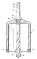
- the drilling unit consists of a hollow drill bit 1 and center drill 2, the hollow drill bit 1 and the center drill 2 being releasably connected to one another by a screw thread 3.
- the center drill 2 is provided in the end region opposite the drilling direction with a receiving shank 2a and in the end region pointing in the drilling direction with a drill head 2b.
- the receiving shaft 2a is provided with a groove 2c which is known per se and in which driving elements of the drive device used can engage.
- the hollow drill bit 1 is bell-shaped in a known manner, the end region on the drilling direction side having cutting elements 1a. This end region of the drill bit 1, provided with cutting elements 1a, is protruded by the drill head 2b in the drilling direction.
- the hollow drill bit 1 has a base 1b which serves to receive one part of the screw thread 3.
- the other part of the screw thread 3 is located on the center drill 2 and in the drilling direction adjoining a collar 2d, which forms an end stop for limiting the screwing-on path of the hollow drill bit 1. Via this collar 2d, any impacts emitted by the drive device are transmitted to the hollow drill bit 1 without the screw thread 3 being unduly stressed.
Landscapes
- Engineering & Computer Science (AREA)
- Mechanical Engineering (AREA)
- Mining & Mineral Resources (AREA)
- Drilling Tools (AREA)
- Processing Of Stones Or Stones Resemblance Materials (AREA)
- Earth Drilling (AREA)
- Drilling And Boring (AREA)
Abstract
Description
- Die Erfindung betrifft eine Bohreinheit mit Hohlbohrkrone und Zentrierbohrer, wobei der Zentrierbohrer in dem der Bohrrichtung entgegengesetzten Endbereich einen Aufnahmeschaft sowie in dem in Bohrrichtung weisenden Endbereich einen Bohrkopf aufweist und die Hohlbohrkrone derart durchsetzt, dass deren bohrrichtungsseitiger Stimbereich vom Bohrkopf und deren der Bohrrichtung entgegengesetzter Stimbereich vom Aufnahmeschaft überragt wird.
- Bohreinheiten mit einer Hohlbohrkrone der eingangs genannten Art werden in Verbindung mit Antriebsgeräten betrieben, welche zumindest zur Abgabe einer Drehbewegung und in gewissen Fällen auch zur Abgabe einer Schlagbewegung ausgelegt sind. Eingesetzt werden die Bohreinheiten in diese Antriebsgeräte mittels eines Aufnahmeschaftes, welcher auf das jeweils zur Anwendung gelangende Antriebsgerät abgestimmt ist.
- Um einem Verlaufen auf oder in dem zu bearbeitenden Material - wie Mauerwerk, Beton, Gestein oder dergleichen - sowohl während des Anbohrens als auch während des weiteren Bohrvorganges entgegenzuwirken, sind die bekannten Bohreinheiten mit einem Zentrierbohrer versehen, welcher an dem in Bohrrichtung weisenden Endbereich einen Bohrkopf aufweist.
- Insbesondere aus logistischen Gründen sind bekannte Bohreinheiten nach einem Baukastenprinzip aufgebaut, dh Aufnahmeschaft, Bohrkopf des Zentrierbohrers sowie Hohlbohrkrone bilden einzelne Teile und werden je nach Bedarfsfall zusammengebaut. Ein solcher Aufbau hat wohl logistische Vorteile, setzt jedoch beim Anwender ausreichende Fachkenntnisse und ein gewisses Geschick voraus. Ausserdem werden an die Verbindungsstellen der einzelnen Teile recht hohe Ansprüche gestellt, so dass ein einwandfreier Zusammenbau dieser erheblichen Beanspruchungen und Verschmutzungen ausgesetzten Teile gewährleistet ist. Insbesondere bereitet die Verbindung des Bohrkopfes des Zentrierbohrers mit den übrigen Teilen erhebliche Schwierigkeiten, um einerseits eine einwandfreie Verbindung und andererseits auch wieder ein Lösen sicherzustellen.
- Um den vorgenannten Nachteilen, welche insbesondere aufgrund der anspruchsvollen Verbindungsstellen auch zu einer Verteuerung aller Teile geführt haben, entgegenzuwirken, ist aus der CH-PS 185 076 eine Bohreinheit bekannt geworden, bei welcher ein Zentrierbohrer derart einstückig ausgebildet ist, dass an einem Ende ein Aufnahmeschaft und am anderen Ende, welches in Bohrrichtung weist, ein Bohrkopf vorhanden ist. Dieser einstückig ausgebildete Zentrierbohrer ist fest mit der Hohlbohrkrone verbunden.
- Mit dieser bekannten Bohreinheit werden die genannten Verbindungsprobleme gelöst, so dass eine recht wirtschaftliche Lösung erzielbar ist. Allerdings darf nicht ausser acht gelassen werden, dass sich verschiedene Antriebsgeräte für solche Bohreinheiten auf dem Markt befinden und somit wieder ein Anpassen des Aufnahmeschaftes an das zur Anwendung gelangende Antriebsgerät erforderlich ist. Darüber hinaus besteht je nach Anwendungsfall das Bedürfnis, die Länge der Bohreinheit durch Verwendung bestimmter Bohrkronen mit bestimmten Aufnahmeschäften zu variieren.
- Mit der genannten, bekannten Bohreinheit lassen sich Anpassungen, insbesondere hinsichtlich Antriebsgeräten und Anwendungsfällen nicht vornehmen, so dass wiederum logistische Probleme entstehen, da jedem Antriebsgerät und jedem Anwendungsfall eine bestimmte Bohreinheit zugeordnet werden muss.
- Der Erfindung liegt die Aufgabe zugrunde, eine Bohreinheit zu schaffen, welche einerseits wirtschaftliche sowie handhabungstechnische Vorteile aufweist und andererseits eine Anpassung an die in Betracht kommenden Anwendungsfälle zulässt.
- Erfindungsgemäss wird die Aufgabe dadurch gelöst, dass zwischen Zentrierbohrer und Hohlbohrkrone eine lösbare Verbindung vorgesehen ist.
- Dadurch, dass der Zentrierbohrer einstückig aus Aufnahmeschaft und Bohrkopf besteht, ist nach der erfindungsgemässen Lösung lediglich noch eine Verbindungsstelle, nämlich zwischen Zentrierbohrer und Hohlbohrkrone, vorhanden. Damit ist die Problematik der Verbindung des Bohrkopfes des Zentrierbohrers mit weiteren Teilen behoben. Die lösbare Verbindung zwischen Zentrierbohrer und Hohlbohrkrone stellt aber dennoch eine Anpassung an die in Betracht kommenden Anwendungsfälle sicher, indem Zentrierbohrer mit unterschiedlich langen Aufnahmeschäften mit für den jeweiligen Anwendungsfall geeigneten Hohlbohrkronen kombiniert werden können. Ebenso lassen sich Hohlbohrkronen unterschiedlicher Durchmesser mit dem jeweiligen Anwendungsfall entsprechenden Aufnahmeschaft kombinieren. Sollten Hohlbohrkrone oder Zentrierbohrer einem vorzeitigen Verschleiss unterliegen, kann das jeweils verschlissene Teil mit einem neuen Teil bestückt werden, so dass nicht die gesamte Bohreinheit ersetzt werden muss, was zu weiteren wirtschaftlichen Vorteilen führt.
- In bevorzugter Weise ist die lösbare Verbindung als Schraubgewinde ausgebildet. Ein solches Schraubgewinde, gegebenenfalls mit entsprechenden Endanschlägen verbunden, stellt eine sichere und jederzeit wieder lösbare Verbindung dar. Es können die an sich bekannten Formen für Schraubgewinde in Betracht kommen Wie Rundgewinde, Trapezgewinde und dergleichen sowie Abwandlungen solcher Schraubgewinde.
- Die Erfindung wird nachstehend anhand einer Zeichnung, welche ein teilweise geschnittenes Ausführungsbeispiel einer Bohreinheit zeigt, näher erläutert.
- Die Bohreinheit besteht aus Hohlbohrkrone 1 und Zentrierbohrer 2, wobei die Hohlbohrkrone 1 und der Zentrierbohrer 2 über ein Schraubgewinde 3 lösbar miteinander verbunden sind.
- Wie die Figur ferner zeigt, ist der Zentrierbohrer 2 in dem der Bohrrichtung entgegengesetzten Endbereich mit einem Aufnahmeschaft 2a und in dem in Bohrrichtung weisenden Endbereich mit einem Bohrkopf 2b versehen. Der Aufnahmeschaft 2a ist mit einer an sich bekannten Nut 2c versehen, in welche Mitnahmeelemente des Anwendung findenden Antriebsgerätes eingreifen können. Die Hohlbohrkrone 1 ist in bekannter Weise glockenförmig ausgebildet, wobei der bohrrichtungsseitige Stimbereich Schneidelemente 1a aufweist. Dieser mit Schneidelementen 1a versehene Stimbereich der Bohrkrone 1 wird vom Bohrkopf 2b in Bohrrichtung überragt.
- In dem der Bohrrichtung abgewandten Endbereich weist die Hohlbohrkrone 1 einen Boden 1b auf, welcher der Aufnahme des einen Teils des Schraubgewindes 3 dient. Der andere Teil des Schraubgewindes 3 befindet sich am Zentrierbohrer 2 und zwar in Bohrrichtung anschliessend an einen Bund 2d, welcher einen Endanschlag zur Begrenzung des Aufschraubewegs der Hohlbohrkrone 1 bildet. Ueber diesen Bund 2d werden gegebenenfalls vom Antriebsgerät abgegebene Schläge auf die Hohlbohrkrone 1 übertragen, ohne dass dabei das Schraubgewinde 3 übermässig beansprucht wird.
Claims (2)
- Bohreinheit mit Hohlbohrkrone (1) und Zentrierbohrer (2), wobei der Zentrierbohrer (2) in dem der Bohrrichtung entgegengesetzten Endbereich einen Aufnahmeschaft (2a) sowie in dem in Bohrrichtung weisenden Endbereich einen Bohrkopf (2b) aufweist und die Hohlbohrkrone (1) derart durchsetzt, dass deren bohrrichtungsseitiger Stimbereich vom Bohrkopf (2b) und deren der Bohrrichtung entgegengesetzter Stimbereich vom Aufnahmeschaft (2a) überragt wird, dadurch gekennzeichnet, dass zwischen Zentrierbohrer (2) und Hohlbohrkrone (1) eine lösbare Verbindung vorgesehen ist.
- Bohreinheit nach Anspruch 1, dadurch gekennzeichnet, dass die lösbare Verbindung als Schraubgewinde (3) ausgebildet ist.
Applications Claiming Priority (2)
| Application Number | Priority Date | Filing Date | Title |
|---|---|---|---|
| DE4436917A DE4436917A1 (de) | 1994-10-15 | 1994-10-15 | Bohreinheit mit Hohlbohrkrone und Zentrierdorn |
| DE4436917 | 1994-10-15 |
Publications (2)
| Publication Number | Publication Date |
|---|---|
| EP0706846A1 true EP0706846A1 (de) | 1996-04-17 |
| EP0706846B1 EP0706846B1 (de) | 1998-12-09 |
Family
ID=6530876
Family Applications (1)
| Application Number | Title | Priority Date | Filing Date |
|---|---|---|---|
| EP95810455A Expired - Lifetime EP0706846B1 (de) | 1994-10-15 | 1995-07-11 | Bohreinheit mit Hohlbohrkrone und Zentrierbohrer |
Country Status (11)
| Country | Link |
|---|---|
| US (1) | US5775445A (de) |
| EP (1) | EP0706846B1 (de) |
| JP (1) | JPH08197532A (de) |
| KR (1) | KR100351537B1 (de) |
| CN (1) | CN1128201A (de) |
| AT (1) | ATE174242T1 (de) |
| CA (1) | CA2160043C (de) |
| DE (2) | DE4436917A1 (de) |
| DK (1) | DK0706846T3 (de) |
| FI (1) | FI954851L (de) |
| HU (1) | HUT72771A (de) |
Cited By (1)
| Publication number | Priority date | Publication date | Assignee | Title |
|---|---|---|---|---|
| US20130101366A1 (en) * | 2011-10-21 | 2013-04-25 | Mark Sanders | Drill bit for removing bolts and other fasteners |
Families Citing this family (10)
| Publication number | Priority date | Publication date | Assignee | Title |
|---|---|---|---|---|
| DE19740277B4 (de) * | 1997-09-13 | 2012-05-24 | Robert Bosch Gmbh | Bohrwerkzeug |
| DE10101451B4 (de) * | 2001-01-15 | 2010-04-01 | Robert Bosch Gmbh | Schneidewerkzeug |
| DE10117262A1 (de) * | 2001-01-17 | 2002-07-18 | Hilti Ag | Gesteinsbohrer |
| CN100411785C (zh) * | 2006-01-04 | 2008-08-20 | 王中华 | 削圈刀 |
| US20110033256A1 (en) * | 2009-08-06 | 2011-02-10 | Johnson He | Annular Sawing Structure |
| CN105195792A (zh) * | 2012-11-26 | 2015-12-30 | 胡小青 | 有效降低制造成本的改良型复合钻头 |
| CN105171064A (zh) * | 2012-11-26 | 2015-12-23 | 胡小青 | 一种复合钻头 |
| BR112018071702A2 (pt) * | 2016-06-08 | 2019-02-19 | Gripp-X B.V. | montagem de serra-copo |
| KR101898989B1 (ko) * | 2018-04-03 | 2018-09-14 | 코리아에프에이(주) | 복합소재단열재 패널용 롱홀쏘 |
| CN115012829B (zh) * | 2022-07-19 | 2024-11-01 | 安徽理工大学 | 一种用于长大地质钻孔施工的内排式直角梯形钻头及方法 |
Citations (2)
| Publication number | Priority date | Publication date | Assignee | Title |
|---|---|---|---|---|
| GB104800A (en) * | 1916-06-09 | 1917-03-22 | Joseph Fletcher | Improved Bit for Cutting Circular Apertures in Wooden Cases, Casks and the like. |
| DE1652518A1 (de) * | 1967-05-10 | 1970-11-05 | Wegner Friweg Werkzeug | Hohlbohrkrone |
Family Cites Families (3)
| Publication number | Priority date | Publication date | Assignee | Title |
|---|---|---|---|---|
| US616928A (en) * | 1899-01-03 | Signors op one-third to charles h | ||
| KR870000798Y1 (ko) * | 1985-04-24 | 1987-03-05 | 김관기 | 상수도용 천공기 |
| US5466099A (en) * | 1993-12-13 | 1995-11-14 | Tdw Delaware, Inc. | Cutter shell for forming holes of improved cylindricality |
-
1994
- 1994-10-15 DE DE4436917A patent/DE4436917A1/de not_active Withdrawn
-
1995
- 1995-07-11 AT AT95810455T patent/ATE174242T1/de active
- 1995-07-11 EP EP95810455A patent/EP0706846B1/de not_active Expired - Lifetime
- 1995-07-11 DE DE59504482T patent/DE59504482D1/de not_active Expired - Lifetime
- 1995-07-11 DK DK95810455T patent/DK0706846T3/da active
- 1995-08-10 KR KR1019950024637A patent/KR100351537B1/ko not_active Expired - Lifetime
- 1995-09-05 US US08/524,013 patent/US5775445A/en not_active Expired - Lifetime
- 1995-10-04 CN CN95117221A patent/CN1128201A/zh active Pending
- 1995-10-06 CA CA002160043A patent/CA2160043C/en not_active Expired - Fee Related
- 1995-10-12 FI FI954851A patent/FI954851L/fi not_active Application Discontinuation
- 1995-10-13 HU HU9502972A patent/HUT72771A/hu unknown
- 1995-10-16 JP JP7267205A patent/JPH08197532A/ja active Pending
Patent Citations (2)
| Publication number | Priority date | Publication date | Assignee | Title |
|---|---|---|---|---|
| GB104800A (en) * | 1916-06-09 | 1917-03-22 | Joseph Fletcher | Improved Bit for Cutting Circular Apertures in Wooden Cases, Casks and the like. |
| DE1652518A1 (de) * | 1967-05-10 | 1970-11-05 | Wegner Friweg Werkzeug | Hohlbohrkrone |
Cited By (1)
| Publication number | Priority date | Publication date | Assignee | Title |
|---|---|---|---|---|
| US20130101366A1 (en) * | 2011-10-21 | 2013-04-25 | Mark Sanders | Drill bit for removing bolts and other fasteners |
Also Published As
| Publication number | Publication date |
|---|---|
| DE4436917A1 (de) | 1996-04-18 |
| JPH08197532A (ja) | 1996-08-06 |
| FI954851A0 (fi) | 1995-10-12 |
| ATE174242T1 (de) | 1998-12-15 |
| CA2160043A1 (en) | 1996-04-16 |
| DK0706846T3 (da) | 1999-08-16 |
| KR100351537B1 (ko) | 2002-12-26 |
| HUT72771A (en) | 1996-05-28 |
| DE59504482D1 (de) | 1999-01-21 |
| KR960013596A (ko) | 1996-05-22 |
| CA2160043C (en) | 1999-12-07 |
| EP0706846B1 (de) | 1998-12-09 |
| FI954851A7 (fi) | 1996-04-16 |
| HU9502972D0 (en) | 1995-12-28 |
| US5775445A (en) | 1998-07-07 |
| CN1128201A (zh) | 1996-08-07 |
| FI954851L (fi) | 1996-04-16 |
Similar Documents
| Publication | Publication Date | Title |
|---|---|---|
| EP1246578B1 (de) | Knochenschraube | |
| DE29713897U1 (de) | Räumwerkzeug zum Aufbohren von Knochenkanälen | |
| DE3108438C2 (de) | Bohrwerkzeug | |
| EP0706846A1 (de) | Bohreinheit mit Hohlbohrkrone und Zentrierbohrer | |
| AT403352B (de) | Hohlbohrwerkzeug mit auswechselbarem zentrierbohrer | |
| DE2837038C2 (de) | Bohrkopf zum Erweitern von Gesteinsbohrlöchern durch Aufwärtsbohren | |
| EP1083295A1 (de) | Bohrwerkzeug | |
| EP0824626A1 (de) | Bohrwerkzeug | |
| DE4437952C2 (de) | Bohrwerkzeug | |
| EP0872297B1 (de) | Kombi-Bohrwerkzeug | |
| EP0778390B1 (de) | Drehschlag-Wendelbohrer | |
| EP0604362B1 (de) | Bohreinheit mit Hohlbohrkrone und Adapter | |
| DE2948665A1 (de) | Schlagbohrer mit zentralem absaugkanal fuer das bohrklein | |
| DE19719051A1 (de) | Markraumbohrkopf vorzugsweise zum Aufsetzen auf flexible Antriebswellen | |
| EP0180246B1 (de) | Schneidewerkzeug | |
| DE2056381A1 (de) | Werkzeug oder Arbeitsgeratschaft, ins besondere fur die Gesteins oder Tiefbohrtech | |
| DE8335453U1 (de) | Zentrierbohrer für eine Hohlbohrkrone | |
| DE2752544C2 (de) | Schlagbohrspitze | |
| DE1427710C (de) | Verfahren zum Bohren einer Serie von Löchern in Baustoffen und Bohrer zur Durchführung des Verfahrens | |
| DE3303466A1 (de) | Drehbare, ein gewindeloch bohrende und gewindeformende schraube | |
| DE1956210A1 (de) | Kupplungsvorrichtung zum Verbinden eines Paares von koaxialen Teilen | |
| DE667592C (de) | Gesteinsbohrer | |
| DE19650014C2 (de) | Rammbohrgerät | |
| DE1483840A1 (de) | Gestaengeverbinder fuer Bohrstangen | |
| DE1766507U (de) | Verbindungsnippel, insbesondere hammernippel mit ueber einsteck- bzw. aufsteckkonus angeschlossener bohrstange. |
Legal Events
| Date | Code | Title | Description |
|---|---|---|---|
| PUAI | Public reference made under article 153(3) epc to a published international application that has entered the european phase |
Free format text: ORIGINAL CODE: 0009012 |
|
| AK | Designated contracting states |
Kind code of ref document: A1 Designated state(s): AT CH DE DK FR GB IT LI NL SE |
|
| 17P | Request for examination filed |
Effective date: 19960503 |
|
| 17Q | First examination report despatched |
Effective date: 19970630 |
|
| GRAG | Despatch of communication of intention to grant |
Free format text: ORIGINAL CODE: EPIDOS AGRA |
|
| GRAG | Despatch of communication of intention to grant |
Free format text: ORIGINAL CODE: EPIDOS AGRA |
|
| GRAH | Despatch of communication of intention to grant a patent |
Free format text: ORIGINAL CODE: EPIDOS IGRA |
|
| GRAH | Despatch of communication of intention to grant a patent |
Free format text: ORIGINAL CODE: EPIDOS IGRA |
|
| GRAA | (expected) grant |
Free format text: ORIGINAL CODE: 0009210 |
|
| AK | Designated contracting states |
Kind code of ref document: B1 Designated state(s): AT CH DE DK FR GB IT LI NL SE |
|
| REF | Corresponds to: |
Ref document number: 174242 Country of ref document: AT Date of ref document: 19981215 Kind code of ref document: T |
|
| REG | Reference to a national code |
Ref country code: CH Ref legal event code: EP |
|
| REF | Corresponds to: |
Ref document number: 59504482 Country of ref document: DE Date of ref document: 19990121 |
|
| ET | Fr: translation filed | ||
| GBT | Gb: translation of ep patent filed (gb section 77(6)(a)/1977) |
Effective date: 19990212 |
|
| REG | Reference to a national code |
Ref country code: DK Ref legal event code: T3 |
|
| PLBE | No opposition filed within time limit |
Free format text: ORIGINAL CODE: 0009261 |
|
| STAA | Information on the status of an ep patent application or granted ep patent |
Free format text: STATUS: NO OPPOSITION FILED WITHIN TIME LIMIT |
|
| 26N | No opposition filed | ||
| REG | Reference to a national code |
Ref country code: GB Ref legal event code: IF02 |
|
| PGFP | Annual fee paid to national office [announced via postgrant information from national office to epo] |
Ref country code: DK Payment date: 20140710 Year of fee payment: 20 Ref country code: NL Payment date: 20140710 Year of fee payment: 20 Ref country code: DE Payment date: 20140709 Year of fee payment: 20 Ref country code: CH Payment date: 20140714 Year of fee payment: 20 |
|
| PGFP | Annual fee paid to national office [announced via postgrant information from national office to epo] |
Ref country code: FR Payment date: 20140708 Year of fee payment: 20 Ref country code: AT Payment date: 20140626 Year of fee payment: 20 Ref country code: GB Payment date: 20140709 Year of fee payment: 20 Ref country code: SE Payment date: 20140711 Year of fee payment: 20 |
|
| PGFP | Annual fee paid to national office [announced via postgrant information from national office to epo] |
Ref country code: IT Payment date: 20140717 Year of fee payment: 20 |
|
| REG | Reference to a national code |
Ref country code: DE Ref legal event code: R071 Ref document number: 59504482 Country of ref document: DE |
|
| REG | Reference to a national code |
Ref country code: DK Ref legal event code: EUP Effective date: 20150711 |
|
| REG | Reference to a national code |
Ref country code: CH Ref legal event code: PL |
|
| REG | Reference to a national code |
Ref country code: NL Ref legal event code: V4 Effective date: 20150711 |
|
| REG | Reference to a national code |
Ref country code: NL Ref legal event code: V4 Effective date: 20150711 |
|
| REG | Reference to a national code |
Ref country code: GB Ref legal event code: PE20 Expiry date: 20150710 |
|
| REG | Reference to a national code |
Ref country code: AT Ref legal event code: MK07 Ref document number: 174242 Country of ref document: AT Kind code of ref document: T Effective date: 20150711 |
|
| REG | Reference to a national code |
Ref country code: SE Ref legal event code: EUG |
|
| PG25 | Lapsed in a contracting state [announced via postgrant information from national office to epo] |
Ref country code: GB Free format text: LAPSE BECAUSE OF EXPIRATION OF PROTECTION Effective date: 20150710 |