EP0706850A1 - Lötbare Kobalt enthaltende kubische Bornitrid-Körper - Google Patents
Lötbare Kobalt enthaltende kubische Bornitrid-Körper Download PDFInfo
- Publication number
- EP0706850A1 EP0706850A1 EP95307249A EP95307249A EP0706850A1 EP 0706850 A1 EP0706850 A1 EP 0706850A1 EP 95307249 A EP95307249 A EP 95307249A EP 95307249 A EP95307249 A EP 95307249A EP 0706850 A1 EP0706850 A1 EP 0706850A1
- Authority
- EP
- European Patent Office
- Prior art keywords
- compact
- metal
- cobalt
- cbn
- compacts
- Prior art date
- Legal status (The legal status is an assumption and is not a legal conclusion. Google has not performed a legal analysis and makes no representation as to the accuracy of the status listed.)
- Granted
Links
Images
Classifications
-
- B—PERFORMING OPERATIONS; TRANSPORTING
- B23—MACHINE TOOLS; METAL-WORKING NOT OTHERWISE PROVIDED FOR
- B23K—SOLDERING OR UNSOLDERING; WELDING; CLADDING OR PLATING BY SOLDERING OR WELDING; CUTTING BY APPLYING HEAT LOCALLY, e.g. FLAME CUTTING; WORKING BY LASER BEAM
- B23K35/00—Rods, electrodes, materials, or media, for use in soldering, welding, or cutting
- B23K35/001—Interlayers, transition pieces for metallurgical bonding of workpieces
- B23K35/004—Interlayers, transition pieces for metallurgical bonding of workpieces at least one of the workpieces being of a metal of the iron group
-
- B—PERFORMING OPERATIONS; TRANSPORTING
- B23—MACHINE TOOLS; METAL-WORKING NOT OTHERWISE PROVIDED FOR
- B23K—SOLDERING OR UNSOLDERING; WELDING; CLADDING OR PLATING BY SOLDERING OR WELDING; CUTTING BY APPLYING HEAT LOCALLY, e.g. FLAME CUTTING; WORKING BY LASER BEAM
- B23K35/00—Rods, electrodes, materials, or media, for use in soldering, welding, or cutting
- B23K35/001—Interlayers, transition pieces for metallurgical bonding of workpieces
-
- B—PERFORMING OPERATIONS; TRANSPORTING
- B23—MACHINE TOOLS; METAL-WORKING NOT OTHERWISE PROVIDED FOR
- B23K—SOLDERING OR UNSOLDERING; WELDING; CLADDING OR PLATING BY SOLDERING OR WELDING; CUTTING BY APPLYING HEAT LOCALLY, e.g. FLAME CUTTING; WORKING BY LASER BEAM
- B23K31/00—Processes relevant to this subclass, specially adapted for particular articles or purposes, but not covered by any single one of main groups B23K1/00 - B23K28/00
- B23K31/02—Processes relevant to this subclass, specially adapted for particular articles or purposes, but not covered by any single one of main groups B23K1/00 - B23K28/00 relating to soldering or welding
- B23K31/025—Connecting cutting edges or the like to tools; Attaching reinforcements to workpieces, e.g. wear-resisting zones to tableware
Definitions
- the present invention relates to the manufacture of brazable polycrystalline cubic boron nitride (CBN) compacts which contain cobalt, and to the joining of such compacts to a substrate by a brazing process.
- CBN cubic boron nitride
- An abrasive or superabrasive compact may be characterized generally as an integrally-bonded structure formed of a sintered, polycrystalline mass of abrasive particles, such as diamond or CBN.
- a suitable bonding matrix which usually is a metal such as cobalt, iron, nickel, platinum, titanium, chromium, tantalum, or an alloy or mixture thereof.
- the bonding matrix which is provided at from about 10% to 30% by volume, additionally may contain a catalyst such as aluminum for CBN recrystallization or growth.
- the compact is supported by its bonding to substrate material to form a laminate or supported compact arrangement.
- This bonding may be effected during the formation of the compact via the HT/HP processing conditions used therefor, or subsequent to the formation of the compact using joining techniques such as soldering, brazing, or adhesive bonding.
- the substrate material is provided as a cemented metal carbide which comprises, for example, tungsten, titanium, or tantalum carbide particles, or a mixture thereof, which are bonded together with a binder of about 6% to about 25% by weight of a metal such as cobalt, nickel, or iron, or a mixture or alloy thereof.
- a metal such as cobalt, nickel, or iron, or a mixture or alloy thereof.
- the basic method for manufacturing the cobalt-containing, polycrystalline CBN compacts of the type described herein involves the placing of an unsintered mass of abrasive, crystalline CBN particles within a protectively shielded metal enclosure which is disposed within the reaction cell of a HT/HP apparatus of a type described further in U.S. Patent Nos. 2,947,611; 2,941,241; 2,941,248; 3,609,818; 3,767,371; 4,289,503; 4,673,414; and 4,954,139. Additionally placed within the enclosure with the abrasive particles is a metal binder or bonding medium which forms the bonding matrix or second phase previously mentioned.
- processing conditions selected as sufficient to effect intercrystalline bonding between adjacent grains of the abrasive particles.
- processing conditions generally involve the imposition for about 3 to 120 minutes of a temperature of at least 1300°C and a pressure of at least 20 kbar.
- the binder or bonding media may be provided in a pre-consolidated form disposed adjacent the crystal particles.
- the metal may be configured as an annulus into which is received a cylinder of abrasive crystal particles, or as a disc which is disposed above or below the crystalline mass.
- the metal may be provided in a powdered form and intermixed with the abrasive crystalline particles, or as a cemented metal carbide or carbide molding powder which may be cold pressed into shape and wherein the cementing agent is provided as the catalyst, solvent, or binder.
- the metal is selected from cobalt, iron, or nickel, or an alloy or mixture thereof, but other metals such as ruthenium, rhodium, palladium, chromium, manganese, tantalum, and alloys and mixtures thereof also may be employed.
- metals such as ruthenium, rhodium, palladium, chromium, manganese, tantalum, and alloys and mixtures thereof also may be employed.
- aluminum or an alloy thereof may be employed as a catalyst or solvent for the CBN, although, as is described in U.S. Patent Nos. 4,181,194 and 4,289,503, CBN compacts can be formed by a direct conversion process without any catalyst.
- the metal binder in whatever form provided, is caused to penetrate or "sweep" into the abrasive layer by means of either diffusion or capillary action, and is thereby made available to function as an interstitial binder.
- the HT/HP conditions which operate in the thermodynamic region wherein CBN is the stable phase, also effect a compaction of the abrasive crystal particles which is charactenzed by intercrystalline CBN-to-CBN bonding wherein parts of each crystalline lattice are shared between adjacent crystal grains.
- the CBN concentration in the compact or in the abrasive table is at least about 50% by volume.
- Polycrystalline diamond and CBN compacts containing a second phase of a cemented carbide or nitride material are exemplary of these so-called “conjoint” or “composite” polycrystalline abrasive compacts.
- thermally-stable and conjoint compacts consist essentially only of abrasive particles and, for the conjoint compacts, of a ceramic, the bonding of these compacts to substrates such as cemented metal carbide supports has proven difficult.
- Such compacts are not as abrasion resistant as would be desired in many applications.
- the present invention is directed to the manufacture of brazable polycrystalline cubic boron nitride (CBN) compacts which contain cobalt, and to the joining of such compacts to a substrate by a brazing process.
- CBN cubic boron nitride
- the present invention provides for the improved brazing of the compacts directly to a tool holder or the like.
- the chemically-bonded coating has been observed to withstand severe deformation without spalling.
- the metal-coated compact of the present invention may be brazed to cemented metal carbide support or the like to form a conventional supported compact, but at a lower cost and with an improved dimensional tolerance than when formed using HT/HP techniques.
- multiple compact layers can be formed in a conventional HT/HP press without the need to include cemented metal carbide support layers in the press.
- the cell space in the press can be maximized for the production of the abrasive compacts layers, which later may be brazed to support layers to form supported compacts.
- brazing may be effected at lower temperatures as compared to the HT/HP bonding techniques heretofore employed, thermal stresses are minimized and composite compacts may be manufactured having ratios of carbide layer thicknesses to compact layer thicknesses which are outside the range of thickness ratios previously considered recommended.
- CBN cubic boron nitride
- a surface of a cobalt-containing CBN compact is metallized by the deposition of a layer of a refractory metal thereon.
- the metallized compact then is heated to a treatment temperature above about 700°C to chemically bond the refractory metal to the surface of the compact for forming a metal coating layer thereon.
- the metal-coated surface of the compact then is brazed to a faying surface of a substrate with a brazing filler metal having a liquidus temperature above about 600°C.
- thermally-stable PCD or CBN compacts Accordingly, production processes requiring a higher service temperature, such as tungsten coating and high temperature brazing, have been limited to the use of thermally-stable PCD or CBN compacts. Unfortunately, these thermally-stable compacts often exhibit certain performance or material properties, such as impact resistance and bondability, which are substantially lower than the cobalt-containing compacts.
- the thermal stability or service temperature for cobalt-containing CBN compacts is not, in fact, the same as that for cobalt-containing PCD compacts. Indeed, it has been found experimentally that the cobalt-containing CBN compacts which are the subject of the present invention are thermally stable at temperatures above 800°C and even up to temperatures of about 1000°C. In hindsight, it is postulated that the greater thermal stability of the cobalt-containing compacts may be explained by the fact that cobalt is less active as a solvent or catalyst for CBN as compared to diamond. That is, and as is described in U.S. Patent Nos.
- the cobalt metal which is used as a solvent or catalyst in the HT/HP forming process in which graphite is converted to diamond, and which is present in the compact as a bonding matrix, becomes active at temperatures of about 700°C at atmospheric pressures.
- the activation of the cobalt catalyzes the back-conversion of diamond to graphite, and thereby contributes to the structural degradation of the compact and to the loss of its capability as an abrasive table.
- cobalt is much less active as a catalyst for CBN than for diamond, it is, apparently, the catalytic effects of the cobalt as to diamond, rather than the differences in the CTE's as between the CBN or diamond particles and the cobalt, which is the limiting factor in the thermal stability of cobalt-containing diamond or CBN compacts.
- cobalt-containing CBN compacts encompass materials, such as those described in U.S. Patent Nos. 3,233,988; 3,743,489; 3,767,371; 3,918,219, contain from about 70% to about 90% by volume of CBN particles and a second phase or bonding matrix of from about 10% to about 30% by volume of cobalt metal or an alloy or mixture thereof.
- Such compacts are manufactured by the General Electric Company under the name BZN ® 6000.
- a method for making an improved, brazable cobalt-containing cubic boron nitride compact.
- the method involves, broadly, the steps of: (a) providing a cobalt-containing CBN compact having at least one surface; (b) metallizing a surface of the cobalt-containing CBN compact by depositing a layer of a refractory metal thereon; and (c) heating the metallized compact to a treatment temperature above about 700°C, and preferably above about 800°C for at least about 30 minutes, to chemically bond the refractory metal to the surface of the compact for forming a metal coating layer thereon.
- the refractory metal must be capable of forming a chemical bond with the abrasive particles of the compact.
- a chemical bond it is meant that the refractory metal is capable of forming borides or nitrides with the CBN particles.
- Typical examples of such metals include titanium, manganese, chromium, vanadium, tungsten, molybdenum, and niobium, with tungsten and alloys and mixtures thereof being preferred from a performance standpoint.
- the metal is chosen such that it will produce a stable chemical bond with the abrasive particles at temperatures less than the degradation temperature of the compact which, for the cobalt-containing compacts of the present invention, is about 1000°C.
- the heat treatment be carried out at too high a temperature, the risks of deterioration of the abrasive particles during heat treatment are increased.
- the heat treatment be effected in an inert, reducing, or non-oxidizing atmosphere such as provided by a neon, argon, hydrogen, or nitrogen gas, or by a vacuum of about 10.4 Torr.
- the metallizing of the compact may be effect at a substantially lower temperature, preferably between about 300°C and 600°C, than the heat treatment step.
- a substantially lower temperature preferably between about 300°C and 600°C
- such metallizing involves the depositing of a refractory metal, such as nickel, copper, titanium, tungsten, niobium, zirconium, vanadium, molybdenum, chromium, hafnium, or an alloy or mixtures thereof, on a surface of the compact.
- any one of a number of known techniques including electrolytic plating, evaporation, chemical vapor deposition (CVD), sputtering, plasma coating, fused salt bath coating, pack diffusion, or vacuum deposition may be used to effect the deposition of the metal layer.
- the metal layer is deposited to have a thickness of from about 2 microns or less to about 150 microns to minimize the development of stresses in the compact.
- the provision of a metal coating layer enhances, for example, the oxidation resistance of the compact during brazing operations, and improves the wetting of the compact by the braze to promote a better adhesion therebetween.
- the metal-coated, cobalt-containing CBN compact as herein described may be brazed to a substrate such as a shank or other holder to form a tool, or to a cemented metal carbide layer to form a supported or composite compact.
- the cemented metal carbide layer may comprise, for example, tungsten, titanium, tantalum, or molybdenum carbide particles, or mixtures thereof, and a metal binder such as cobalt, nickel, or iron, ruthenium, rhodium, palladium, platinum, chromium, manganese, tantalum, osmium, iridium, or a mixture or alloy thereof.
- the metal-coated, cobalt-containing CBN compacts of the invention are readily brazed either to cemented carbide supports or directly to tool holders and the like, a carbide support therefore need not be included in the reaction cell of the HT/HP apparatus during the forming of the CBN compact. Accordingly, multiple CBN compact layers may be formed to a precise dimensional tolerance without the need to include support layers in the reaction cell of the HT/HP press. As the cemented metal carbide support layers constitute a considerable expense in the forming process and take up valuable cell space, their elimination increases productivity and thereby makes the manufacturing process more economical.
- CBN compacts having two metal-coated sides may be made in accordance with the present invention for bonding by brazing or the like to a tool such as a twist drill.
- the provision of metal-coated CBN compacts according to the invention additionally facilitates the production of supported compacts that heretofore would have violated the previously recommended ratio of carbide layer thickness to abrasive table thickness. That is, a typical CBN compact, as manufactured, results in the abrasive table being in compression as long as the ratio of WC to CBN is greater than about 1. When portions of the WC layer are ground or otherwise removed making the WC/CBN ration less than about 1, the abrasive table may be placed into tension and crack.
- the brazing of the coated CBN compacts of the present invention may be effected at temperatures lower than the 1300°C necessary to form supported CBN compacts in the conventional HT/HP manner, the stresses in the compact layer are minimized.
- the use of the essentially stress-free compacts of the present invention therefore facilitates the manufacturing of thinner compacts without a concomitantly increased risk of stress cracking.
- brazing advantageously may be effected at temperatures higher and for times longer than that heretofore known.
- braze alloys with liquidus temperatures of less than 700°C were thought necessary unless the compact was provided in a thermally-stable form.
- the use of such low temperature braze alloys has found, unfortunately, only limited applicability in the marketplace as forming bonds having characteristically lower strengths as compared to higher temperature alloys.
- the brazing of the metal-coated compacts of the invention may be effected through techniques which would be considered conventional for thermally-stable compacts, such techniques being described more fully in U.S. Patent Nos. 4,063,909; 4,225,322; 4,319,707; 4,527,998; 4,601,423; 4,670,025; 4,772,294; 4,850,523; 4,941,891; 4,968,326; 4,931,363; 5,032,147; and 5,273,557, and in Sani and Grant, "Brazing of Free-Standing PCBN and PCD Products, "Finer Points," Vol. 5, No. 3, pp. 15-18 (1993).
- the brazing of the metal-coated compacts to a substrate involves the placing of a layer of the braze filler metal between the metallized surface of the compact and the faying surface of the substrate; mating the metallized surface of the compact to the faying surface of the substrate; heating the filler metal to a temperature above its liquidus temperature; and cooling the filler metal to a temperature below its liquidus temperature to bond the metallized surface of the compact to the faying surface of the substrate.
- the braze alloy may be heated to a temperature above its liquidus for at least about 2 minutes and for even as long as about 2 hours without adversely affecting the structural integrity of the compacts.
- Any of a number of braze filler metals such as alloys of silver, copper, titanium, palladium, platinum, zinc, nickel, gold, and manganese, and mixtures thereof, may be employed, although a TiCuSil alloy (Ti-4.5%, Cu-26.7%, Ag-balance) generally is considered preferred.
- the brazing may be conducted in an inert reducing, or non-oxidizing atmosphere such as provided by a neon, argon, hydrogen, or nitrogen gas, or by a vacuum of about 10 ⁇ 4 Torr, in order to minimize oxidation or other degradation of the materials.
- an inert reducing, or non-oxidizing atmosphere such as provided by a neon, argon, hydrogen, or nitrogen gas, or by a vacuum of about 10 ⁇ 4 Torr, in order to minimize oxidation or other degradation of the materials.
- the metal-coated compacts of the invention may be brazed using less aggressive, more standard techniques such as, for example, with a filler alloy having a liquidus of about 600°C.
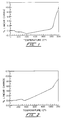
- Fig. 1 shown is the thermal expansion curve for a representative sample (BZN ® 6000, General Electric Company) for the cobalt-containing CBN compacts which are the subject of the invention.
- the curve reveals that the thermal expansion of the sample does not deviate from the lower or thermally-stable temperature curve until at about 1000°C.
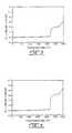
- the material is seen has having a thermal response similar to that exhibited by the TiN-containing reference compact (BZN ® 8100, General Electric Company) shown in Fig. 2.
- the cobalt-containing PCD samples of Fig. 3 (Compax ® 1500) and Fig. 4 (Compax ® 1600) show a deviation from the thermally-stable temperature curve at a considerably lower temperature.
- Such behavior translates, as has been observed experimentally, to a higher thermal stability limit for the cobalt-contain CBN compacts of the invention as compared to cobalt-containing PCD compacts.
- a brazed CBN-tungsten carbide subassembly from Example 3 was prepared for an end milling evaluation by attachment to a conventional Ingersoll LNE443-01 carbide insert with a low temperature braze alloy.
- a standard, i.e., HT/HP bonded, cobalt-containing CBN supported compact (BZN ® 6000), and standard and brazed titanium nitride-containing CBN supported compacts (BZN ® 8100) additionally were evaluated for comparison.
- the inserts were held in a negative Ingersoll 600D12R02 end mill having a nominal outside diameter of 3 cm (1.23 inch).
- a typical class 30 gray cast iron (Neenah Foundry) having a Brinell hardness of 200 was selected as the workpiece material.
- the material had a pearlitic/graphite structure with a Type-A graphite flake distribution, and was machined prior to testing to remove all surface scale and oxidation.
- the inserts without chamfer or hone, were performance tested in a flycutting mode.
- the radial depth or width-of-cut was set at 1.27 cm (0.500 inch) to minimize the effects of radial chip thinning, and the axial depth-of-cut (DOC) was set for a total engagement with the workpiece thickness of 2.375 cm (0.935 inch).
- the cutter velocity was maintained at 457.2 surface meters per minute (1500 surface feet per minute(SFM)) for feedrates of 0.0007 inch per tooth (ipt) and 0.001 ipt, and a 9.42 cm (3.710 inch) length-of-cut (LOC).
- the slower 0.0007 ipt feedrate was selected to minimize any chipping of the inserts.
- Test Condition Summary Machine Le Blond/Makino 25 H.P.
- Workpiece Class 30 Gray Cast iron (Bhn 200) Milling Cutter: 1.23 inch Ingersoll 600D12R02 End Mill (Negative Geometry) Cutting mode: Single Insert Flycutting Insert Type: LNE-443-01, Grade 111 Edge Prep.: None Hone: None SFM: 1500 RPM: 4658 IPT: 0.0007 and 0.001 IPM: 3.3 and 4.7 DOC: 0.935 inch Radial Depth: 0.500 inch Coolant: None
- BZN® 6000 (Brazed) 0.0010 0.0207 0.8 1.74 0.0207 2.5 16 BZN® 6000 (Standard) 0.0010 0.0255 5.8 3.47 None 2.5 16 BZN® 8100 (Standard) 0.0010 0.0365 1.7 3.47 0.0081 2.5 16 BZN® 8100 (Brazed) 0.0010 0.0530 1.7 3.47 0.0261 2.5 16 BZN® 6000 (Brazed) 0.0007 0.0210 28.8 41.64 0.0019 2.0 22 BZN® 6000 (Standard) 0.0007 0.0255 5.8 6.94 None 2.0 16 BZN® 8100 (Standard) 0.0007 0.0367 5.8 6.94 None 1.9 19 BZN® 8100 (Brazed) 0.0007 0.0522 5.8 6.94 None 2.0 18
Landscapes
- Engineering & Computer Science (AREA)
- Mechanical Engineering (AREA)
- Ceramic Products (AREA)
Applications Claiming Priority (2)
| Application Number | Priority Date | Filing Date | Title |
|---|---|---|---|
| US322810 | 1989-03-13 | ||
| US32281094A | 1994-10-13 | 1994-10-13 |
Publications (2)
| Publication Number | Publication Date |
|---|---|
| EP0706850A1 true EP0706850A1 (de) | 1996-04-17 |
| EP0706850B1 EP0706850B1 (de) | 1999-10-06 |
Family
ID=23256531
Family Applications (1)
| Application Number | Title | Priority Date | Filing Date |
|---|---|---|---|
| EP95307249A Expired - Lifetime EP0706850B1 (de) | 1994-10-13 | 1995-10-12 | Lötbare Kobalt enthaltende kubische Bornitrid-Körper |
Country Status (5)
| Country | Link |
|---|---|
| EP (1) | EP0706850B1 (de) |
| JP (1) | JPH08225376A (de) |
| KR (1) | KR960013524A (de) |
| DE (1) | DE69512599T2 (de) |
| ES (1) | ES2138152T3 (de) |
Cited By (4)
| Publication number | Priority date | Publication date | Assignee | Title |
|---|---|---|---|---|
| US7429152B2 (en) | 2003-06-17 | 2008-09-30 | Kennametal Inc. | Uncoated cutting tool using brazed-in superhard blank |
| US7592077B2 (en) | 2003-06-17 | 2009-09-22 | Kennametal Inc. | Coated cutting tool with brazed-in superhard blank |
| EP2397246A4 (de) * | 2009-05-27 | 2016-06-15 | Nat Inst Of Advanced Ind Scien | Verbundener körper |
| EP1122226B2 (de) † | 1999-12-03 | 2022-10-26 | Sumitomo Electric Industries, Ltd. | Beschichtete PCBN-Schneidewerzeuge |
Citations (7)
| Publication number | Priority date | Publication date | Assignee | Title |
|---|---|---|---|---|
| DE849505C (de) * | 1945-03-30 | 1952-09-15 | Eisen & Stahlind Ag | Verfahren zum Aufloeten von Formkoerpern aus Hartmetallegierungen auf eine metallische Unterlage |
| FR2210474A1 (en) * | 1972-12-19 | 1974-07-12 | Bernard Rene | Coating cemented carbide articles - with brazable metal layer |
| EP0104063A2 (de) * | 1982-09-16 | 1984-03-28 | De Beers Industrial Diamond Division (Proprietary) Limited | Bornitrid enthaltende verschleissfeste Körper |
| CH649098A5 (en) * | 1982-06-02 | 1985-04-30 | Krupp Widia Schweiz Ag | Process for the surface treatment of a sintered material part and sintered material part produced by this process |
| US4567110A (en) * | 1979-11-13 | 1986-01-28 | Massachusetts Institute Of Technology | High-temperature brazed ceramic joints |
| EP0184455A2 (de) * | 1984-12-06 | 1986-06-11 | De Beers Industrial Diamond Division (Proprietary) Limited | Verbindungsverfahren |
| EP0397515A1 (de) * | 1989-05-12 | 1990-11-14 | De Beers Industrial Diamond Division (Proprietary) Limited | Drahtziehwerkzeug |
-
1995
- 1995-10-11 JP JP7262640A patent/JPH08225376A/ja active Pending
- 1995-10-12 KR KR1019950035026A patent/KR960013524A/ko not_active Withdrawn
- 1995-10-12 EP EP95307249A patent/EP0706850B1/de not_active Expired - Lifetime
- 1995-10-12 DE DE69512599T patent/DE69512599T2/de not_active Expired - Fee Related
- 1995-10-12 ES ES95307249T patent/ES2138152T3/es not_active Expired - Lifetime
Patent Citations (7)
| Publication number | Priority date | Publication date | Assignee | Title |
|---|---|---|---|---|
| DE849505C (de) * | 1945-03-30 | 1952-09-15 | Eisen & Stahlind Ag | Verfahren zum Aufloeten von Formkoerpern aus Hartmetallegierungen auf eine metallische Unterlage |
| FR2210474A1 (en) * | 1972-12-19 | 1974-07-12 | Bernard Rene | Coating cemented carbide articles - with brazable metal layer |
| US4567110A (en) * | 1979-11-13 | 1986-01-28 | Massachusetts Institute Of Technology | High-temperature brazed ceramic joints |
| CH649098A5 (en) * | 1982-06-02 | 1985-04-30 | Krupp Widia Schweiz Ag | Process for the surface treatment of a sintered material part and sintered material part produced by this process |
| EP0104063A2 (de) * | 1982-09-16 | 1984-03-28 | De Beers Industrial Diamond Division (Proprietary) Limited | Bornitrid enthaltende verschleissfeste Körper |
| EP0184455A2 (de) * | 1984-12-06 | 1986-06-11 | De Beers Industrial Diamond Division (Proprietary) Limited | Verbindungsverfahren |
| EP0397515A1 (de) * | 1989-05-12 | 1990-11-14 | De Beers Industrial Diamond Division (Proprietary) Limited | Drahtziehwerkzeug |
Cited By (6)
| Publication number | Priority date | Publication date | Assignee | Title |
|---|---|---|---|---|
| EP1122226B2 (de) † | 1999-12-03 | 2022-10-26 | Sumitomo Electric Industries, Ltd. | Beschichtete PCBN-Schneidewerzeuge |
| US7429152B2 (en) | 2003-06-17 | 2008-09-30 | Kennametal Inc. | Uncoated cutting tool using brazed-in superhard blank |
| US7592077B2 (en) | 2003-06-17 | 2009-09-22 | Kennametal Inc. | Coated cutting tool with brazed-in superhard blank |
| CN1805820B (zh) * | 2003-06-17 | 2010-09-29 | 钴碳化钨硬质合金公司 | 具有钎焊超硬刀坯的无涂层刀具 |
| US7946792B2 (en) | 2003-06-17 | 2011-05-24 | Kennametal, Inc. | Uncoated cutting tool using brazed-in superhard blank |
| EP2397246A4 (de) * | 2009-05-27 | 2016-06-15 | Nat Inst Of Advanced Ind Scien | Verbundener körper |
Also Published As
| Publication number | Publication date |
|---|---|
| ES2138152T3 (es) | 2000-01-01 |
| EP0706850B1 (de) | 1999-10-06 |
| DE69512599T2 (de) | 2000-05-11 |
| JPH08225376A (ja) | 1996-09-03 |
| DE69512599D1 (de) | 1999-11-11 |
| KR960013524A (ko) | 1996-05-22 |
Similar Documents
| Publication | Publication Date | Title |
|---|---|---|
| EP0223585B1 (de) | Sinterhartmetallkörper für Werkzeuge | |
| EP0157625B1 (de) | Werkzeug aus Verbundwerkstoff | |
| EP0779129B1 (de) | Verfahren zur Herstellung eines Schleifkörpers mit verbesserten Eigenschaften | |
| US5697994A (en) | PCD or PCBN cutting tools for woodworking applications | |
| US4636253A (en) | Diamond sintered body for tools and method of manufacturing same | |
| EP2101903B1 (de) | Schleifpresskörper mit verbesserter bearbeitbarkeit | |
| JP5420533B2 (ja) | コーティングされたcbn | |
| US20050050801A1 (en) | Doubled-sided and multi-layered PCD and PCBN abrasive articles | |
| US20050210755A1 (en) | Doubled-sided and multi-layered PCBN and PCD abrasive articles | |
| EP0365218A1 (de) | Mit Spannuten versehenes polykristallines Diamantwerkzeug und ein Verfahren zu dessen Herstellung | |
| JP2012131700A (ja) | 焼結体 | |
| KR20090007761A (ko) | cBN 복합체 물질 및 공구 | |
| JP5603954B2 (ja) | 超硬要素、その使用方法及びその製造方法 | |
| EP0474092A2 (de) | Verwendung von hitzebeständigen Diamant- oder CBN-Compacts als Bohrerschneideinsätze | |
| EP1709135B1 (de) | Beschichtete schleifmittel | |
| EP0816304A2 (de) | Keramisch gebundener kompakter Körper aus kubischem Bornitrid | |
| EP0706850B1 (de) | Lötbare Kobalt enthaltende kubische Bornitrid-Körper | |
| GB2091763A (en) | Laminated sintered compositions including boron nitride | |
| WO2002029127A2 (en) | Abrasive and wear resistant material | |
| JP2001040446A (ja) | ダイヤモンド含有硬質部材及びその製造方法 | |
| JPH0665745A (ja) | ダイヤモンド被覆硬質材料およびその製造法 | |
| JPH01225774A (ja) | 高硬度多結晶ダイヤモンド工具 | |
| JP3353335B2 (ja) | ダイヤモンド被覆硬質材料およびその製造法 | |
| JPH05295545A (ja) | ダイヤモンド被覆硬質材料およびその製造法 | |
| Rabinkin et al. | Advances in brazing: 6. Brazing of diamonds and cubic boron nitride |
Legal Events
| Date | Code | Title | Description |
|---|---|---|---|
| PUAI | Public reference made under article 153(3) epc to a published international application that has entered the european phase |
Free format text: ORIGINAL CODE: 0009012 |
|
| AK | Designated contracting states |
Kind code of ref document: A1 Designated state(s): BE DE ES FR GB IT |
|
| 17P | Request for examination filed |
Effective date: 19961017 |
|
| 17Q | First examination report despatched |
Effective date: 19980609 |
|
| GRAG | Despatch of communication of intention to grant |
Free format text: ORIGINAL CODE: EPIDOS AGRA |
|
| GRAG | Despatch of communication of intention to grant |
Free format text: ORIGINAL CODE: EPIDOS AGRA |
|
| GRAH | Despatch of communication of intention to grant a patent |
Free format text: ORIGINAL CODE: EPIDOS IGRA |
|
| GRAH | Despatch of communication of intention to grant a patent |
Free format text: ORIGINAL CODE: EPIDOS IGRA |
|
| GRAA | (expected) grant |
Free format text: ORIGINAL CODE: 0009210 |
|
| AK | Designated contracting states |
Kind code of ref document: B1 Designated state(s): BE DE ES FR GB IT |
|
| REF | Corresponds to: |
Ref document number: 69512599 Country of ref document: DE Date of ref document: 19991111 |
|
| ITF | It: translation for a ep patent filed | ||
| REG | Reference to a national code |
Ref country code: ES Ref legal event code: FG2A Ref document number: 2138152 Country of ref document: ES Kind code of ref document: T3 |
|
| ET | Fr: translation filed | ||
| PLBE | No opposition filed within time limit |
Free format text: ORIGINAL CODE: 0009261 |
|
| STAA | Information on the status of an ep patent application or granted ep patent |
Free format text: STATUS: NO OPPOSITION FILED WITHIN TIME LIMIT |
|
| 26N | No opposition filed | ||
| REG | Reference to a national code |
Ref country code: GB Ref legal event code: IF02 |
|
| PGFP | Annual fee paid to national office [announced via postgrant information from national office to epo] |
Ref country code: FR Payment date: 20020918 Year of fee payment: 8 |
|
| PGFP | Annual fee paid to national office [announced via postgrant information from national office to epo] |
Ref country code: BE Payment date: 20021023 Year of fee payment: 8 |
|
| PGFP | Annual fee paid to national office [announced via postgrant information from national office to epo] |
Ref country code: ES Payment date: 20021106 Year of fee payment: 8 |
|
| PG25 | Lapsed in a contracting state [announced via postgrant information from national office to epo] |
Ref country code: ES Free format text: LAPSE BECAUSE OF NON-PAYMENT OF DUE FEES Effective date: 20031013 |
|
| PG25 | Lapsed in a contracting state [announced via postgrant information from national office to epo] |
Ref country code: BE Free format text: LAPSE BECAUSE OF NON-PAYMENT OF DUE FEES Effective date: 20031031 |
|
| BERE | Be: lapsed |
Owner name: *GENERAL ELECTRIC CY Effective date: 20031031 |
|
| PG25 | Lapsed in a contracting state [announced via postgrant information from national office to epo] |
Ref country code: FR Free format text: LAPSE BECAUSE OF NON-PAYMENT OF DUE FEES Effective date: 20040630 |
|
| REG | Reference to a national code |
Ref country code: FR Ref legal event code: ST |
|
| PGFP | Annual fee paid to national office [announced via postgrant information from national office to epo] |
Ref country code: GB Payment date: 20041006 Year of fee payment: 10 |
|
| PGFP | Annual fee paid to national office [announced via postgrant information from national office to epo] |
Ref country code: DE Payment date: 20041130 Year of fee payment: 10 |
|
| REG | Reference to a national code |
Ref country code: GB Ref legal event code: 732E |
|
| REG | Reference to a national code |
Ref country code: ES Ref legal event code: FD2A Effective date: 20031013 |
|
| PG25 | Lapsed in a contracting state [announced via postgrant information from national office to epo] |
Ref country code: IT Free format text: LAPSE BECAUSE OF NON-PAYMENT OF DUE FEES;WARNING: LAPSES OF ITALIAN PATENTS WITH EFFECTIVE DATE BEFORE 2007 MAY HAVE OCCURRED AT ANY TIME BEFORE 2007. THE CORRECT EFFECTIVE DATE MAY BE DIFFERENT FROM THE ONE RECORDED. Effective date: 20051012 Ref country code: GB Free format text: LAPSE BECAUSE OF NON-PAYMENT OF DUE FEES Effective date: 20051012 |
|
| PG25 | Lapsed in a contracting state [announced via postgrant information from national office to epo] |
Ref country code: DE Free format text: LAPSE BECAUSE OF NON-PAYMENT OF DUE FEES Effective date: 20060503 |
|
| GBPC | Gb: european patent ceased through non-payment of renewal fee |
Effective date: 20051012 |