EP0706900B1 - Couche de substratage pour récepteur utilisée dans un transfert thermique de colorant - Google Patents
Couche de substratage pour récepteur utilisée dans un transfert thermique de colorant Download PDFInfo
- Publication number
- EP0706900B1 EP0706900B1 EP95115878A EP95115878A EP0706900B1 EP 0706900 B1 EP0706900 B1 EP 0706900B1 EP 95115878 A EP95115878 A EP 95115878A EP 95115878 A EP95115878 A EP 95115878A EP 0706900 B1 EP0706900 B1 EP 0706900B1
- Authority
- EP
- European Patent Office
- Prior art keywords
- dye
- layer
- mole
- poly
- receiving
- Prior art date
- Legal status (The legal status is an assumption and is not a legal conclusion. Google has not performed a legal analysis and makes no representation as to the accuracy of the status listed.)
- Expired - Lifetime
Links
Classifications
-
- B—PERFORMING OPERATIONS; TRANSPORTING
- B41—PRINTING; LINING MACHINES; TYPEWRITERS; STAMPS
- B41M—PRINTING, DUPLICATING, MARKING, OR COPYING PROCESSES; COLOUR PRINTING
- B41M5/00—Duplicating or marking methods; Sheet materials for use therein
- B41M5/26—Thermography ; Marking by high energetic means, e.g. laser otherwise than by burning, and characterised by the material used
- B41M5/40—Thermography ; Marking by high energetic means, e.g. laser otherwise than by burning, and characterised by the material used characterised by the base backcoat, intermediate, or covering layers, e.g. for thermal transfer dye-donor or dye-receiver sheets; Heat, radiation filtering or absorbing means or layers; combined with other image registration layers or compositions; Special originals for reproduction by thermography
- B41M5/42—Intermediate, backcoat, or covering layers
- B41M5/44—Intermediate, backcoat, or covering layers characterised by the macromolecular compounds
-
- B—PERFORMING OPERATIONS; TRANSPORTING
- B41—PRINTING; LINING MACHINES; TYPEWRITERS; STAMPS
- B41M—PRINTING, DUPLICATING, MARKING, OR COPYING PROCESSES; COLOUR PRINTING
- B41M2205/00—Printing methods or features related to printing methods; Location or type of the layers
- B41M2205/32—Thermal receivers
-
- Y—GENERAL TAGGING OF NEW TECHNOLOGICAL DEVELOPMENTS; GENERAL TAGGING OF CROSS-SECTIONAL TECHNOLOGIES SPANNING OVER SEVERAL SECTIONS OF THE IPC; TECHNICAL SUBJECTS COVERED BY FORMER USPC CROSS-REFERENCE ART COLLECTIONS [XRACs] AND DIGESTS
- Y10—TECHNICAL SUBJECTS COVERED BY FORMER USPC
- Y10S—TECHNICAL SUBJECTS COVERED BY FORMER USPC CROSS-REFERENCE ART COLLECTIONS [XRACs] AND DIGESTS
- Y10S428/00—Stock material or miscellaneous articles
- Y10S428/913—Material designed to be responsive to temperature, light, moisture
-
- Y—GENERAL TAGGING OF NEW TECHNOLOGICAL DEVELOPMENTS; GENERAL TAGGING OF CROSS-SECTIONAL TECHNOLOGIES SPANNING OVER SEVERAL SECTIONS OF THE IPC; TECHNICAL SUBJECTS COVERED BY FORMER USPC CROSS-REFERENCE ART COLLECTIONS [XRACs] AND DIGESTS
- Y10—TECHNICAL SUBJECTS COVERED BY FORMER USPC
- Y10S—TECHNICAL SUBJECTS COVERED BY FORMER USPC CROSS-REFERENCE ART COLLECTIONS [XRACs] AND DIGESTS
- Y10S428/00—Stock material or miscellaneous articles
- Y10S428/914—Transfer or decalcomania
-
- Y—GENERAL TAGGING OF NEW TECHNOLOGICAL DEVELOPMENTS; GENERAL TAGGING OF CROSS-SECTIONAL TECHNOLOGIES SPANNING OVER SEVERAL SECTIONS OF THE IPC; TECHNICAL SUBJECTS COVERED BY FORMER USPC CROSS-REFERENCE ART COLLECTIONS [XRACs] AND DIGESTS
- Y10—TECHNICAL SUBJECTS COVERED BY FORMER USPC
- Y10T—TECHNICAL SUBJECTS COVERED BY FORMER US CLASSIFICATION
- Y10T428/00—Stock material or miscellaneous articles
- Y10T428/27—Web or sheet containing structurally defined element or component, the element or component having a specified weight per unit area [e.g., gms/sq cm, lbs/sq ft, etc.]
- Y10T428/273—Web or sheet containing structurally defined element or component, the element or component having a specified weight per unit area [e.g., gms/sq cm, lbs/sq ft, etc.] of coating
-
- Y—GENERAL TAGGING OF NEW TECHNOLOGICAL DEVELOPMENTS; GENERAL TAGGING OF CROSS-SECTIONAL TECHNOLOGIES SPANNING OVER SEVERAL SECTIONS OF THE IPC; TECHNICAL SUBJECTS COVERED BY FORMER USPC CROSS-REFERENCE ART COLLECTIONS [XRACs] AND DIGESTS
- Y10—TECHNICAL SUBJECTS COVERED BY FORMER USPC
- Y10T—TECHNICAL SUBJECTS COVERED BY FORMER US CLASSIFICATION
- Y10T428/00—Stock material or miscellaneous articles
- Y10T428/31504—Composite [nonstructural laminate]
- Y10T428/31507—Of polycarbonate
-
- Y—GENERAL TAGGING OF NEW TECHNOLOGICAL DEVELOPMENTS; GENERAL TAGGING OF CROSS-SECTIONAL TECHNOLOGIES SPANNING OVER SEVERAL SECTIONS OF THE IPC; TECHNICAL SUBJECTS COVERED BY FORMER USPC CROSS-REFERENCE ART COLLECTIONS [XRACs] AND DIGESTS
- Y10—TECHNICAL SUBJECTS COVERED BY FORMER USPC
- Y10T—TECHNICAL SUBJECTS COVERED BY FORMER US CLASSIFICATION
- Y10T428/00—Stock material or miscellaneous articles
- Y10T428/31504—Composite [nonstructural laminate]
- Y10T428/31855—Of addition polymer from unsaturated monomers
-
- Y—GENERAL TAGGING OF NEW TECHNOLOGICAL DEVELOPMENTS; GENERAL TAGGING OF CROSS-SECTIONAL TECHNOLOGIES SPANNING OVER SEVERAL SECTIONS OF THE IPC; TECHNICAL SUBJECTS COVERED BY FORMER USPC CROSS-REFERENCE ART COLLECTIONS [XRACs] AND DIGESTS
- Y10—TECHNICAL SUBJECTS COVERED BY FORMER USPC
- Y10T—TECHNICAL SUBJECTS COVERED BY FORMER US CLASSIFICATION
- Y10T428/00—Stock material or miscellaneous articles
- Y10T428/31504—Composite [nonstructural laminate]
- Y10T428/31855—Of addition polymer from unsaturated monomers
- Y10T428/31909—Next to second addition polymer from unsaturated monomers
Definitions
- This invention relates to dye-receiving elements used in thermal dye transfer, and more particularly to a particular subbing layer for such elements.
- thermal transfer systems have been developed to obtain prints from pictures which have been generated electronically from a color video camera.
- an electronic picture is first subjected to color separation by color filters.
- the respective color-separated images are then converted into electrical signals.
- These signals are then operated on to produce cyan, magenta and yellow electrical signals.
- These signals are then transmitted to a thermal printer.
- a cyan, magenta or yellow dye-donor element is placed face-to-face with a dye-receiving element.
- the two are then inserted between a thermal printing head and a platen roller.
- a line-type thermal printing head is used to apply heat from the back of the dye-donor sheet.
- the thermal printing head has many heating elements and is heated up sequentially in response to the cyan, magenta and yellow signals. The process is then repeated for the other two colors. A color hard copy is thus obtained which corresponds to the original picture viewed on a screen. Further details of this process and an apparatus for carrying it out are contained in U.S. Patent 4,621,271.
- Dye-receiving elements for thermal dye transfer generally comprise a polymeric dye image-receiving layer coated on a support.
- a compression, or cushion intermediate layer for example as taught in U.S. Patent 4,734,397 may also be present between the support and the dye image-receiving layer.
- cushion layers promote better contact between a dye-donor element and the dye-receiving element, which minimizes the formation of image defects during dye transfer and improves the scratch resistance of the dye-receiving element.
- subbing layers for example as taught by U.S. Patent 4,748,150, may also be present between the various layers to promote adhesion.
- U.S. Patent 5,055,444 discloses an intermediate receiving element for thermal dye transfer wherein a subbing layer of crosslinked poly(vinyl acetal-co-vinyl alcohol) is used between a dye image-receiving layer and a separable polyolefin layer. The dye image-receiving layer is separated from the intermediate receiver for transfer to a final receiving element. There is no disclosure in this patent that a cushion layer of an acrylic polymer should be used instead of a separable polyolefin layer.
- U.S. Patent 5,147,846 discloses the use of a subbing layer between a cushion layer and a dye image-receiving layer of a dye-receiving element.
- the particular subbing layers disclosed include copolymers of vinylidene chloride, e.g., poly(acrylonitrile-co-vinylidene chloride-co-acrylic acid). While these subbing layers have proved effective, a problem has developed in the stability to light, or dye fade, for the dyes, especially the cyan dye, which are transferred to the dye-receiving element. Such dye fade will invariably result in undesirable image deterioration.
- a dye-receiving element for thermal dye transfer comprising a support having on one side thereof, in order, a cushion layer of an acrylic polymer, a subbing layer, and a polymeric dye image-receiving layer, wherein the subbing layer is a poly(vinyl acetal) and is present at a coverage of at least 0.17 g/m 2 .
- the poly(vinyl acetal) has the following formula: wherein
- R in the above formula is CH 3 .
- A is at least 60 mole %.
- Poly(vinyl acetals) within the above formula include poly(vinyl formal), poly(vinyl acetal), poly(vinyl propional), poly(vinyl butyral), poly(vinyl benzal) and substituted poly(vinyl benzal).
- a cushion layer is employed in the receiving element which is an acrylic polymer.
- acrylic polymer these polymers are more fully described in U.S. Patent 4,734,397. These polymers include poly(methyl methacrylate), poly(styrene-co-acrylonitrile), poly(n-butyl acrylate-co-acrylic acid), etc.
- the cushion layer is a copolymer of butyl acrylate and acrylic acid.
- the compliant or cushion layer and subbing layer may be coated simultaneously, if desired.
- the support for the dye-receiving element of the invention includes films of poly(ether sulfone(s)), polyimides, poly(vinyl chloride), cellulose esters such as cellulose acetate, poly(ethylene terephthalate), and poly(ethylene naphthalate).
- the support is transparent.
- the support may be employed at any desired thickness, usually from about 10 ⁇ m to 1000 ⁇ m.
- the dye image-receiving layer of the dye-receiving elements of the invention may comprise, for example, a polycarbonate, a polyurethane, a polyester, poly(vinyl chloride), poly(styrene-co-acrylonitrile), polycaprolactone or mixtures thereof.
- polycarbonates are employed.
- the dye image-receiving layer may be present in any amount which is effective for the intended purpose. In general, good results have been obtained at from about 1 to about 10 g/m 2 .
- An overcoat layer may be further coated over the dye-receiving layer such as those described in U.S. Patent 4,775,657.
- dye-donor elements may be used with the dye-receiving element of the invention.
- Such donor elements generally comprise a support having thereon a dye-containing layer. Any dye can be used in the dye-donor employed in the invention provided it is transferable to the dye-receiving layer by the action of heat. Especially good results have been obtained with diffusible dyes.
- Dye donors applicable for use in the present invention are described, e.g., in U.S. Patents 4,916,112, 4,927,803 and 5,023,228.
- the dye-donor element employed in certain embodiments of the invention may be used in sheet form or in a continuous roll or ribbon. If a continuous roll or ribbon is employed, it may have only one dye thereon, mixtures of dyes or may have alternating areas of different dyes such as cyan, magenta, yellow, black, etc., as disclosed in U.S. Patent 4,541,830.
- a process of forming a dye transfer image according to the invention comprises:
- a dye-donor element which comprises a poly(ethylene terephthalate) support coated with sequential repeating areas of cyan, magenta and yellow dye, and the dye transfer process steps are sequentially performed for each color to obtain a three-color dye transfer image.
- Thermal printing heads which can be used to transfer dye from dye-donor elements to the receiving elements of the invention are available commercially. There can be employed, for example, a Fujitsu Thermal Head (FTP-040 MCS001), a TDK Thermal Head F415 HH7-1089 or a Rohm Thermal Head KE 2OO8-F3. Alternatively, other known sources of energy for thermal dye transfer, such as laser or ultrasound, may be used.
- FTP-040 MCS001 Fujitsu Thermal Head
- TDK Thermal Head F415 HH7-1089 a Rohm Thermal Head KE 2OO8-F3.
- other known sources of energy for thermal dye transfer such as laser or ultrasound, may be used.
- a thermal dye transfer assemblage of the invention comprises a) a dye-donor element as described above, and b) a dye-receiving element as described above, the dye-receiving element being in a superposed relationship with the dye-donor element so that the dye layer of the donor element is in contact with the dye image-receiving layer of the receiving element.
- the above assemblage is formed on three occasions during the time when heat is applied by the thermal printing head. After the first dye is transferred, the elements are peeled apart. A second dye-donor element (or another area of the donor element with a different dye area) is then brought into register with the dye-receiving element and the process repeated. The third color is obtained in the same manner.
- a protective layer element was prepared by coating on one side of a 6 ⁇ m PET support a protective layer comprising Sekisui KS-1 (a poly(vinyl acetal-co-vinyl alcohol) of the same composition as KS-3 but with a viscosity of 50-100 cps.) (Sekisui Chemical Co.), (0.45 g/m 2 ), and divinylbenzene beads, 4.0 ⁇ m, (0.086 g/m 2 ) from 3-pentanone.
- Sekisui KS-1 a poly(vinyl acetal-co-vinyl alcohol) of the same composition as KS-3 but with a viscosity of 50-100 cps.) (Sekisui Chemical Co.), (0.45 g/m 2 ), and divinylbenzene beads, 4.0 ⁇ m, (0.086 g/m 2 ) from 3-pentanone.
- a dye-donor element of sequential areas of yellow, magenta, and cyan dye was prepared by coating the following layers, in order, on a 6 ⁇ m PET support:
- Tests were run with the above dye-receiver and dye-donor elements by placing the dye side of a dye-donor element, approximately 10 cm by 13 cm in area, in contact with the polymeric dye image-receiving layer side of a dye-receiving element of the same area.
- the assemblage was fastened to the top of a motor-driven 56 mm diameter rubber roller and a TDK Thermal Head L-231 was pressed with a force of approximately 23 Newton against the dye-donor element side of the assemblage pushing the dye-donor against the rubber roller.
- the imaging electronics were activated and the assemblage was drawn between the printing head and the roller at 26.2 mm/s.
- the resistive elements in the head were pulsed in a specified pattern for 29 ⁇ s/pulse at 128 ⁇ s intervals during the 8.2 ⁇ s/dot line printing time to create an image.
- the protective layer element When the image had been formed, the protective layer element was placed in contact with the printed image and heated uniformly at an energy level equivalent to a maximum print dye density (2.52 mJ/dot) with the thermal print head to permanently adhere the polymeric film to the print. At the end of the heating cycle, the dye-donor support was peeled away leaving the polymeric film adhering to the print.
- Neutral stepped images were obtained by printing sequentially from the three donor patches.
- the Status A red, green and blue transmission densities of the stepped images were obtained.
- the imaged dye-receivers, laminated with protective layers as described above, were then tested for their light stability by subjecting them to High-Intensity Daylight fading (HID fading) for 7 days, 50 kLux, 5400 deg. K., °C., approximately 25% RH, and the densities were reread.
- the percent density losses after fade at 0.5 density were calculated.
- Dye-receiver elements were prepared by coating on a transparent 175 ⁇ m PET the following layers:
- the peel strength of the dye-receiver elements with various subbing compositions was measured using a T-Peel adhesive test (ASTM D 1876) on an 1122 Instron tensile testing instrument. Samples were laminated with a 175 ⁇ m PET support coated with Bostik 7962® copolyester adhesive (Bostik Chemical Group, Emhart Corp.) at 121°C, cooled, and the receiver/laminate package cut into 15 cm x 2 cm strips. The samples were T-peeled at a peeling rate of 10.1 cm/minute. Five to six repeat tests were run with each sample to provide an average peel strength as shown below in Table 2.
- test series was run to provide a comparison of different laydowns (g/m 2 ) of PVAc's in their effectiveness to bond to the overlying dye-receiving layer.
- a dye-receiver element in accordance with the invention was prepared by coating on a transparent 175 ⁇ m (7 mil) PET support the following layers:
- each dye-receiver element was then subjected to a tape adhesion test as generally described by W. T. Diefenbach in Tappi 45 , 840 (1962).
- the receiver surface was first carefully scored in an "X" pattern.
- a small area (approximately 1.9 cm x 5.1 cm) of Scotch® Magic Transparent Tape (available from 3M Corp.) was firmly pressed by hand over the scored area of the receiver surface, leaving enough area free to serve as a handle for pulling the tape. The latter was rapidly pulled off the receiver element at a 90° angle. In the ideal case, no material of the receiver layer would be removed, indicating a "passing" performance.
Landscapes
- Physics & Mathematics (AREA)
- Optics & Photonics (AREA)
- Thermal Transfer Or Thermal Recording In General (AREA)
Claims (10)
- Elément récepteur de colorant pour transfert thermique de colorant comprenant un support porteur sur l'un de ses côtés, dans l'ordre, d'une couche d'amortissement constituée d'un polymère acrylique, d'une couche substratante et d'une couche réceptrice d'image de colorant polymère, dans lequel ladite couche substratante est à base d'acétal polyvinylique et est présente avec un titre d'au moins 0,17 g/m2.
- Elément récepteur de colorant selon la revendication 1, dans lequel ledit acétal polyvinylique a la formule suivante :
 R est un atome d'hydrogène, un groupe -(CH2)x-CH3, ou un groupe
 x est 0 à 6 ;Y est un atome d'hydrogène, un halogène, un groupe alkyle ou un groupe alcoxyle comportant de 1 à 6 atomes de carbone, un groupe aryle comportant de 6 à 10 atomes de carbone ou un groupe carboxylate ;A est compris dans l'intervalle de 30 à 95 moles %,B est compris dans l'intervalle de 5 à 65 moles %,C est compris dans l'intervalle de 0 à 25 moles %.
 - Elément selon la revendication 1, dans lequel ledit support est transparent.
- Elément selon la revendication 1, dans lequel ladite couche d'amortissement comprend un copolymère de l'acrylate de butyle et de l'acide acrylique.
- Elément selon la revendication 2, dans lequel R est le groupe CH3 et A est d'au moins 60 moles %.
- Elément selon la revendication 1, dans lequel ladite couche réceptrice d'image de colorant polymère comprend un polycarbonate.
- Procédé de formation d'une image par transfert de colorant comprenant les étapes consistant à :a) chauffer, conformément à l'image, un élément donneur de colorant comportant un support porteur d'une couche de colorant comprenant un colorant dispersé dans un liant, etb) transférer une image de colorant sur un élément récepteur de colorant pour former ladite image par transfert de colorant, dans lequel ledit récepteur de colorant comprend un support portant sur l'un de ses côtés, dans l'ordre, une couche d'amortissement de polymère acrylique, d'une couche substratante et d'une couche réceptrice d'image de colorant polymère, dans lequel ladite couche substratante est à base d'acétal polyvinylique et est présente avec un titre d'au moins 0,17 g/m2.
- Procédé selon la revendication 7, dans lequel ledit acétal polyvinylique a la formule suivante :
 R est un atome d'hydrogène, un groupe -(CH2)x-CH3, ou un groupe
 x est 0 à 6,Y est un atome d'hydrogène, un halogène, un groupe alkyle ou un groupe alcoxyle comportant de 1 à 6 atomes de carbone, un groupe aryle comportant de 6 à 10 atomes de carbone ou un groupe carboxylate ;A est compris dans l'intervalle de 30 à 95 moles %,B est compris dans l'intervalle de 5 à 65 moles %, etC est compris dans l'intervalle de 0 à 25 moles %.
 - Assemblage pour transfert thermique de colorant comprenant :a) un élément donneur de colorant comportant un support porteur d'une couche de colorant comprenant un colorant dispersé dans un liant, etb) un élément récepteur de colorant comprenant un support porteur sur l'un de ses côté, dans l'ordre, d'une couche d'amortissement de polymère acrylique, d'une couche substratante et d'une couche réceptrice d'image de colorant polymère, dans lequel ladite couche substratante est à base d'acétal polyvinylique et est présente à une couverture d'au moins 0,17 g/m2,ledit élément récepteur de colorant étant en relation superposée avec ledit élément donneur de colorant d'une manière telle que ladite couche de colorant se trouve en contact avec ladite couche réceptrice d'image de colorant.
- Assemblage selon la revendication 9, dans lequel ledit acétal polyvinylique a la formule suivante :
 R est un atome d'hydrogène, un groupe -(CH2)x-CH3, ou un groupe
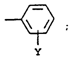 x est 0 à 6,Y est un atome d'hydrogène, un halogène, un groupe alkyle ou un groupe alcoxyle comportant de 1 à 6 atomes de carbone, un groupe aryle comportant de 6 à 10 atomes de carbone ou un groupe carboxylate,A est compris dans l'intervalle de 30 à 95 moles %,B est compris dans l'intervalle de 5 à 65 moles %, etC est compris dans l'intervalle de 0 à 25 moles %.
Applications Claiming Priority (2)
| Application Number | Priority Date | Filing Date | Title |
|---|---|---|---|
| US321273 | 1989-03-09 | ||
| US08/321,273 US5420095A (en) | 1994-10-11 | 1994-10-11 | Subbing layer for receiver used in thermal dye transfer |
Publications (2)
| Publication Number | Publication Date |
|---|---|
| EP0706900A1 EP0706900A1 (fr) | 1996-04-17 |
| EP0706900B1 true EP0706900B1 (fr) | 1997-04-02 |
Family
ID=23249916
Family Applications (1)
| Application Number | Title | Priority Date | Filing Date |
|---|---|---|---|
| EP95115878A Expired - Lifetime EP0706900B1 (fr) | 1994-10-11 | 1995-10-09 | Couche de substratage pour récepteur utilisée dans un transfert thermique de colorant |
Country Status (4)
| Country | Link |
|---|---|
| US (1) | US5420095A (fr) |
| EP (1) | EP0706900B1 (fr) |
| JP (1) | JPH08175036A (fr) |
| DE (1) | DE69500211T2 (fr) |
Families Citing this family (6)
| Publication number | Priority date | Publication date | Assignee | Title |
|---|---|---|---|---|
| US5789340A (en) * | 1996-07-31 | 1998-08-04 | Eastman Kodak Company | Subbing layer for composite thermal dye transfer ID card stock |
| JP5133928B2 (ja) * | 2009-03-30 | 2013-01-30 | 富士フイルム株式会社 | 感熱転写シートと感熱転写受像シートを用いた画像形成方法 |
| US7993559B2 (en) * | 2009-06-24 | 2011-08-09 | Eastman Kodak Company | Method of making thermal imaging elements |
| US8377846B2 (en) * | 2009-06-24 | 2013-02-19 | Eastman Kodak Company | Extruded image receiver elements |
| US8258078B2 (en) | 2009-08-27 | 2012-09-04 | Eastman Kodak Company | Image receiver elements |
| CN102582310A (zh) * | 2012-02-22 | 2012-07-18 | 焦作市卓立烫印材料有限公司 | 一种热升华转印膜及其制备方法 |
Family Cites Families (10)
| Publication number | Priority date | Publication date | Assignee | Title |
|---|---|---|---|---|
| US4541830A (en) | 1982-11-11 | 1985-09-17 | Matsushita Electric Industrial Co., Ltd. | Dye transfer sheets for heat-sensitive recording |
| US4621271A (en) | 1985-09-23 | 1986-11-04 | Eastman Kodak Company | Apparatus and method for controlling a thermal printer apparatus |
| US4734397A (en) | 1986-10-08 | 1988-03-29 | Eastman Kodak Company | Compression layer for dye-receiving element used in thermal dye transfer |
| US4775657A (en) | 1987-06-16 | 1988-10-04 | Eastman Kodak Company | Overcoat for dye image-receiving layer used in thermal dye transfer |
| US4748150A (en) | 1987-09-15 | 1988-05-31 | Eastman Kodak Company | Subbing layer for dye image-receiving layer used in thermal dye transfer |
| US4927803A (en) | 1989-04-28 | 1990-05-22 | Eastman Kodak Company | Thermal dye transfer receiving layer of polycarbonate with nonaromatic diol |
| US4916112A (en) | 1989-06-30 | 1990-04-10 | Eastman Kodak Company | Slipping layer containing particulate ester wax for dye-donor element used in thermal dye transfer |
| US5055444A (en) * | 1990-05-04 | 1991-10-08 | Eastman Kodak Company | Intermediate receiver subbing layer for thermal dye transfer |
| US5023228A (en) | 1990-06-13 | 1991-06-11 | Eastman Kodak Company | Subbing layer for dye-donor element used in thermal dye transfer |
| US5147846A (en) * | 1990-12-21 | 1992-09-15 | Eastman Kodak Company | Surfactant for use in thermal dye transfer receiving element subbing layer |
-
1994
- 1994-10-11 US US08/321,273 patent/US5420095A/en not_active Expired - Fee Related
-
1995
- 1995-10-09 JP JP7261678A patent/JPH08175036A/ja active Pending
- 1995-10-09 EP EP95115878A patent/EP0706900B1/fr not_active Expired - Lifetime
- 1995-10-09 DE DE69500211T patent/DE69500211T2/de not_active Expired - Fee Related
Also Published As
| Publication number | Publication date |
|---|---|
| EP0706900A1 (fr) | 1996-04-17 |
| US5420095A (en) | 1995-05-30 |
| DE69500211T2 (de) | 1997-07-10 |
| JPH08175036A (ja) | 1996-07-09 |
| DE69500211D1 (de) | 1997-05-07 |
Similar Documents
| Publication | Publication Date | Title |
|---|---|---|
| EP0513800B1 (fr) | Mélanges d'alcool polyvinylique et polyvinylpyrrolidone comme couches adhésives pour des éléments donneurs de colorants pour le transfert thermique de colorants | |
| EP0228066B1 (fr) | Mélange de polymères pour un élément récepteur de colorant utilisé pour le transfert de colorant par la chaleur | |
| EP0657302B1 (fr) | Elément donneur de colorant pour transfert thermique de colorant contenant und couche protectrice transférable | |
| EP0603570B1 (fr) | Elément récepteur de colorant pour transfert thermique | |
| EP0318946A2 (fr) | Procédé pour accroître la densité d'images obtenues par le transfert thermique | |
| EP0455213B1 (fr) | Couche adhésive pour un élément récepteur de colorant intermédiaire utilisé pour le transfert par la chaleur | |
| EP0792758B1 (fr) | Système pour le transfert thermique de colorant avec récepteurs mélange polymérique bas-Tg | |
| EP0257579B1 (fr) | Dérivés stabilisants alcoxylés pour un élément récepteur de colorant utilisé pour le transfert thermique | |
| EP0348989B1 (fr) | Esters phtaliques dans une couche réceptrice pour modifier la densité du transfert de colorant | |
| EP0747231A1 (fr) | Système pour transfert thermique de colorant avec récepteur polymérique bas-Tg et contenant un groupe acide | |
| EP0318945B1 (fr) | Matériau pour l'amélioration de l'efficacité du transfert de colorant aux éléments donneurs de colorants utilisés pour le transfert thermique | |
| EP0706900B1 (fr) | Couche de substratage pour récepteur utilisée dans un transfert thermique de colorant | |
| EP0603569B1 (fr) | Elément récepteur de colorant pour transfert thermique | |
| EP0522566B1 (fr) | Copolymères d'esters d'acides alkyl 2 amido méthoxy acryliques utilisés comme couches de substratage faisant barrage aux colorants | |
| EP0733488B1 (fr) | Elément donneur de colorant pour transfert thermique de colorant contenant une couche protectrice transférable | |
| EP0716930B1 (fr) | Elément réceptrice pour transfert thermique de colorants pour mordanter des colorants ioniques | |
| EP0673791B1 (fr) | Couche adhésive pour élément donneur de colorant utilisé dans le transfert thermique de colorant | |
| EP0581263B1 (fr) | Elément récepteur de colorant pour transfert thermique avec couche réceptrice de colorant d'un polymère epichlorohydrin modifié par bisphénol-A | |
| EP0936079B1 (fr) | Elément récepteur pour le transfert thermique de colorant | |
| EP0885747B1 (fr) | Agent de libération pour un élément donneur de colorant utilisé dans le transfert thermique de colorant | |
| EP0649758B1 (fr) | Couche intermédiaire pour une couche de glissement dans un élément donneur de colorant utilisé pour transfert thermique de colorant | |
| EP0513630B1 (fr) | Feuille de glissement contenant un dérivéd'acide phosphonique pour un élément donneur de colorant utilisé dans le transfert thermique de colorant | |
| EP0714788B1 (fr) | Couche de couverture pour élément récepteur de colorant pour transfert thermique | |
| EP0950539B1 (fr) | Elément récepteur de colorant pour le transfert thermique | |
| EP0318944A2 (fr) | Amélioration de l'efficacité du transfert de colorant aux élément donneurs de colorants utilisés pour le transfert thermique |
Legal Events
| Date | Code | Title | Description |
|---|---|---|---|
| PUAI | Public reference made under article 153(3) epc to a published international application that has entered the european phase |
Free format text: ORIGINAL CODE: 0009012 |
|
| AK | Designated contracting states |
Kind code of ref document: A1 Designated state(s): DE FR GB |
|
| 17P | Request for examination filed |
Effective date: 19960521 |
|
| GRAG | Despatch of communication of intention to grant |
Free format text: ORIGINAL CODE: EPIDOS AGRA |
|
| 17Q | First examination report despatched |
Effective date: 19960722 |
|
| GRAH | Despatch of communication of intention to grant a patent |
Free format text: ORIGINAL CODE: EPIDOS IGRA |
|
| GRAH | Despatch of communication of intention to grant a patent |
Free format text: ORIGINAL CODE: EPIDOS IGRA |
|
| GRAA | (expected) grant |
Free format text: ORIGINAL CODE: 0009210 |
|
| AK | Designated contracting states |
Kind code of ref document: B1 Designated state(s): DE FR GB |
|
| REF | Corresponds to: |
Ref document number: 69500211 Country of ref document: DE Date of ref document: 19970507 |
|
| ET | Fr: translation filed | ||
| PLBE | No opposition filed within time limit |
Free format text: ORIGINAL CODE: 0009261 |
|
| STAA | Information on the status of an ep patent application or granted ep patent |
Free format text: STATUS: NO OPPOSITION FILED WITHIN TIME LIMIT |
|
| 26N | No opposition filed | ||
| PGFP | Annual fee paid to national office [announced via postgrant information from national office to epo] |
Ref country code: FR Payment date: 19981006 Year of fee payment: 4 |
|
| PG25 | Lapsed in a contracting state [announced via postgrant information from national office to epo] |
Ref country code: FR Free format text: LAPSE BECAUSE OF NON-PAYMENT OF DUE FEES Effective date: 20000630 |
|
| REG | Reference to a national code |
Ref country code: FR Ref legal event code: ST |
|
| PGFP | Annual fee paid to national office [announced via postgrant information from national office to epo] |
Ref country code: DE Payment date: 20011030 Year of fee payment: 7 |
|
| REG | Reference to a national code |
Ref country code: GB Ref legal event code: IF02 |
|
| PG25 | Lapsed in a contracting state [announced via postgrant information from national office to epo] |
Ref country code: DE Free format text: LAPSE BECAUSE OF NON-PAYMENT OF DUE FEES Effective date: 20030501 |
|
| PGFP | Annual fee paid to national office [announced via postgrant information from national office to epo] |
Ref country code: GB Payment date: 20030915 Year of fee payment: 9 |
|
| PG25 | Lapsed in a contracting state [announced via postgrant information from national office to epo] |
Ref country code: GB Free format text: LAPSE BECAUSE OF NON-PAYMENT OF DUE FEES Effective date: 20041009 |
|
| GBPC | Gb: european patent ceased through non-payment of renewal fee |
Effective date: 20041009 |