EP0706910A1 - Machine de pose en continu du câble d'alimentation d'un caténaire électrique - Google Patents
Machine de pose en continu du câble d'alimentation d'un caténaire électrique Download PDFInfo
- Publication number
- EP0706910A1 EP0706910A1 EP95890164A EP95890164A EP0706910A1 EP 0706910 A1 EP0706910 A1 EP 0706910A1 EP 95890164 A EP95890164 A EP 95890164A EP 95890164 A EP95890164 A EP 95890164A EP 0706910 A1 EP0706910 A1 EP 0706910A1
- Authority
- EP
- European Patent Office
- Prior art keywords
- machine
- drum
- wire
- tension
- axis
- Prior art date
- Legal status (The legal status is an assumption and is not a legal conclusion. Google has not performed a legal analysis and makes no representation as to the accuracy of the status listed.)
- Granted
Links
Images

Classifications
-
- B—PERFORMING OPERATIONS; TRANSPORTING
- B60—VEHICLES IN GENERAL
- B60M—POWER SUPPLY LINES, AND DEVICES ALONG RAILS, FOR ELECTRICALLY- PROPELLED VEHICLES
- B60M1/00—Power supply lines for contact with collector on vehicle
- B60M1/12—Trolley lines; Accessories therefor
- B60M1/28—Manufacturing or repairing trolley lines
Definitions
- the invention relates to a machine for the continuous laying of a contact wire and / or a suspension cable of an electrical overhead line of a track while maintaining the tension specified for the laid overhead line, with a machine frame supported on rail bogies, a wire drum rotatable about a drum axis and mounted in the longitudinal direction, one Height and side-adjustable crane boom with a rotatably mounted deflection roller and a tension device positioned in the pull-off direction of the contact wire between the wire drum and the deflection roller, which has a braking device for applying the correct tension with continuous machine operation.
- Such a machine is already known from EP 0 416 136 B1, with which the contact wire and the suspension cable of an overhead line of a railroad track are continuously laid together and are kept under the required tension during assembly.
- the contact wire and the suspension cable are each unwound from a wire drum mounted on the machine frame and pass through a tension device, in order to be brought into the correct position in terms of height and side using a separate, adjustable deflection roller.
- the two tension devices are each equipped with a braking device, with the help of which the tension of the installed overhead line is regulated according to the railway regulations, while the machine travels continuously along the track.
- Each wire drum is slidably arranged in the longitudinal direction of the drum axis on its own support frame - together with the associated tension device - this drum axis running essentially horizontally and in the cross-machine direction.
- the object of the present invention is to provide a generic machine with which those wire drums can also be easily unwound, in which the contact wire is wound onto the drum with a plane of symmetry running approximately parallel to the drum axis.
- the contact wire is already provided for processing with respect to its plane of symmetry in the assembly position when the wire drum is positioned.
- a straight-line unwinding of the contact wire which is independent of the unwinding progress, is ensured while avoiding bending.
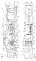
- a machine 1 shown in FIGS. 1 and 2 for the continuous laying of a contact wire 2 and / or a suspension cable 3 of an electrical overhead line has a machine frame 6 which is supported on a track 5 by rail trolleys 4.
- a driver's cabin 7 or a working cabin 8, which are provided with control devices 9, are arranged at each end thereof.
- Two drive assemblies 10 connected to the machine frame 6 serve to act on travel drives 11 of the rail undercarriages 4 and a hydraulic pump 12 for supplying energy to the further drives of the machine 1, which will be described below.
- a wire drum 15, on which the contact wire 2 to be laid or the supporting cable 3 is rolled up, can be rotated about a drum axis 16 and can be displaced in the longitudinal direction on the machine frame 6, as can be seen more clearly from FIG. 3.
- a tension device 26 can be seen from the wire drum 15 in the longitudinal direction of the machine or downstream of it in the withdrawal direction (see arrow 44) of the contact wire 2, which in turn is followed by a rotatably mounted deflection roller 17. This is located at the free end of a crane boom 18 which can be adjusted in height and laterally via drives 19 and is connected to it via a joint 20 which is effective on all sides.
- the wire drum 15 is fastened by means of bearing supports 21 to a drum holder 22 which is mounted on a support frame 23 so as to be pivotable about a horizontal pivot axis 24 running in the cross-machine direction.
- a drive 25 enables the drum holder 22 and the wire drum 15 to be pivoted together by 90 ° from a working position in which the drum axis 16 runs in the vertical direction to a second position in which the drum axis 16 is arranged horizontally. This position, drawn in dash-dotted lines, is adopted for replacing the wire drum 15.
- the bearing support 21 together with a rotary drive 27 assigned to the wire drum 15 is mounted on a slide rail 28 and in The longitudinal direction of the drum axis 16 is designed to be displaceable relative to the drum holder 22 by means of a drive 29.
- the two bearing supports 21 can be spaced apart from one another for installing or removing the wire drum 15.
- the rotary drive 27 is equipped with a torque arm 30.
- the support frame 23 is now mounted on the machine frame 6 together with the wire drum 15 and the drum holder 22 along guides 31 in the vertical direction.
- drives 32 are used, which are articulated on a support 33 connected to the machine frame 6 and on the support frame 23.
- the contact wire 2 (not shown in FIG. 3) is rolled up on the wire drum 15 such that it is already in the correct position corresponding to the misplaced end position with a vertical plane of symmetry when the drum is in the vertical working position.
- the vertical adjustment or readjustment of the wire drum 15 during the pulling off of the contact wire 2 from the drum ensures that it is always introduced horizontally into the tension device 26 (see FIG. 1), thereby causing the wire to kink when it is unrolled from the wire drum 15 is largely avoided.
- the tension device 26 consists essentially of two - grooves - deflecting rollers 34 with a relatively large diameter, which are arranged one behind the other in the longitudinal direction of the machine and are coupled to one another by means of a drive chain 35, one of the deflecting rollers 34 being acted upon by a braking device 36.
- the drive chain 35 is held under the correct tension by means of a tensioning device 37.
- the two deflection rollers 34 are mounted on a swivel frame 38 which is displaceable on horizontal guides 39 running perpendicular to the machine longitudinal direction by means of drives 40 in the cross machine direction and is additionally designed to be pivotable relative to the guides 39 about an axis 41 aligned parallel to the machine longitudinal direction.
- the deflection roller 34 connected to the braking device 36 is also equipped with a brake disc 42 which interacts with an emergency brake 43 in order to prevent an uncontrolled event of a failure of the braking device 36 To prevent pulling off the contact wire 2.
- the transverse displacement of the swivel frame 38 ensures that the contact wire 2 drawn off from the wire drum 15 is inserted in exactly aligned fashion into the grooves of the deflection roller 34, so that the wire does not slip off the roller.
Landscapes
- Engineering & Computer Science (AREA)
- Manufacturing & Machinery (AREA)
- Mechanical Engineering (AREA)
- Electric Cable Installation (AREA)
- Ropes Or Cables (AREA)
- Current-Collector Devices For Electrically Propelled Vehicles (AREA)
- Carriers, Traveling Bodies, And Overhead Traveling Cranes (AREA)
- Manufacturing Of Electric Cables (AREA)
- Yarns And Mechanical Finishing Of Yarns Or Ropes (AREA)
- Duct Arrangements (AREA)
- Shaping By String And By Release Of Stress In Plastics And The Like (AREA)
Applications Claiming Priority (2)
| Application Number | Priority Date | Filing Date | Title |
|---|---|---|---|
| AT0192694A ATA192694A (de) | 1994-10-12 | 1994-10-12 | Maschine zum kontinuierlichen verlegen eines fahrdrahtes einer elektrischen oberleitung |
| AT1926/94 | 1994-10-12 |
Publications (2)
| Publication Number | Publication Date |
|---|---|
| EP0706910A1 true EP0706910A1 (fr) | 1996-04-17 |
| EP0706910B1 EP0706910B1 (fr) | 1998-04-29 |
Family
ID=3524016
Family Applications (1)
| Application Number | Title | Priority Date | Filing Date |
|---|---|---|---|
| EP95890164A Expired - Lifetime EP0706910B1 (fr) | 1994-10-12 | 1995-09-18 | Machine de pose en continu du câble d'alimentation d'un caténaire électrique |
Country Status (11)
| Country | Link |
|---|---|
| EP (1) | EP0706910B1 (fr) |
| JP (1) | JP3023660U (fr) |
| CN (1) | CN1042713C (fr) |
| AT (2) | ATA192694A (fr) |
| CZ (1) | CZ281470B6 (fr) |
| DE (1) | DE59502042D1 (fr) |
| FI (1) | FI108342B (fr) |
| NO (1) | NO305858B1 (fr) |
| PL (1) | PL176651B1 (fr) |
| RU (1) | RU2102261C1 (fr) |
| SK (1) | SK281275B6 (fr) |
Cited By (6)
| Publication number | Priority date | Publication date | Assignee | Title |
|---|---|---|---|---|
| RU2140859C1 (ru) * | 1997-02-17 | 1999-11-10 | Франц Плассер Банбаумашинен-Индустригезельшафт Мбх | Машина для прокладки контактного провода рельсового пути |
| EP0992391A1 (fr) * | 1998-10-07 | 2000-04-12 | Franz Plasser Bahnbaumaschinen-Industriegesellschaft m.b.H. | Machine pour la pose d'un caténaire de voie |
| RU2149774C1 (ru) * | 1998-06-04 | 2000-05-27 | Франц Плассер Банбаумашинен - Индустригезельшафт М.Б.Х. | Машина для монтажа контактного провода надземной линии |
| CN1065834C (zh) * | 1997-03-13 | 2001-05-16 | 弗兰茨普拉塞铁路机械工业股份有限公司 | 架设接触导线用的机械 |
| DE10138294C1 (de) * | 2001-08-10 | 2003-02-06 | Db Netz Ag | Verfahren und Vorrichtung zum Auswechseln eines Fahrdrahtes an einer Oberleitung |
| CN106965708A (zh) * | 2015-12-31 | 2017-07-21 | 海宁伊满阁太阳能科技有限公司 | 一种设施农地方法及设施农地 |
Families Citing this family (6)
| Publication number | Priority date | Publication date | Assignee | Title |
|---|---|---|---|---|
| ATA140697A (de) * | 1997-08-21 | 1999-01-15 | Plasser Bahnbaumasch Franz | Maschine zum verlegen eines fahrdrahtes |
| RU2223184C2 (ru) * | 2001-12-11 | 2004-02-10 | Закрытое акционерное общество "Балтийская строительная компания-Санкт-Петербург" | Устройство для монтажа контактной сети электрифицированных железных дорог |
| AT6149U1 (de) * | 2002-04-24 | 2003-05-26 | Plasser Bahnbaumasch Franz | Maschine zum verlegen einer fahrleitung |
| CN100486836C (zh) * | 2004-08-16 | 2009-05-13 | 曾进忠 | 电气化铁路接触网恒张力放线车架装置 |
| CN102126502A (zh) * | 2010-01-13 | 2011-07-20 | 襄樊金鹰轨道车辆有限责任公司 | 一种铁路电气化作业车 |
| CN104627028B (zh) * | 2015-02-13 | 2016-10-26 | 中国铁建电气化局集团第五工程有限公司 | 一种刚性接触网接触线安装涂抹油脂的装置 |
Citations (3)
| Publication number | Priority date | Publication date | Assignee | Title |
|---|---|---|---|---|
| DE2012248A1 (de) * | 1970-03-14 | 1971-10-07 | Licentia Gmbh | Montage von Fahrdrahten |
| US4213596A (en) | 1978-10-30 | 1980-07-22 | Fuji Jokogyo Kabushiki Kaisha | Wheeled, overhead wire installing apparatus |
| EP0416136A1 (fr) | 1988-10-14 | 1991-03-13 | Franz Plasser Bahnbaumaschinen-Industriegesellschaft m.b.H. | Machine circulant sur voie pour la pose d'un fil de trolley et/ou d'un câble porteur d'un catenaire de voie |
Family Cites Families (1)
| Publication number | Priority date | Publication date | Assignee | Title |
|---|---|---|---|---|
| CN1030299C (zh) * | 1990-10-03 | 1995-11-22 | 弗朗茨普拉瑟尔铁路机械工业有限公司 | 检查接触网导线用的机械 |
-
1994
- 1994-10-12 AT AT0192694A patent/ATA192694A/de not_active IP Right Cessation
-
1995
- 1995-09-14 CZ CZ952381A patent/CZ281470B6/cs not_active IP Right Cessation
- 1995-09-18 EP EP95890164A patent/EP0706910B1/fr not_active Expired - Lifetime
- 1995-09-18 DE DE59502042T patent/DE59502042D1/de not_active Expired - Lifetime
- 1995-09-18 AT AT95890164T patent/ATE165565T1/de active
- 1995-09-20 SK SK1164-95A patent/SK281275B6/sk not_active IP Right Cessation
- 1995-10-06 PL PL95310875A patent/PL176651B1/pl not_active IP Right Cessation
- 1995-10-11 NO NO954034A patent/NO305858B1/no not_active IP Right Cessation
- 1995-10-11 RU RU95117222A patent/RU2102261C1/ru not_active IP Right Cessation
- 1995-10-11 JP JP1995010751U patent/JP3023660U/ja not_active Expired - Lifetime
- 1995-10-11 FI FI954834A patent/FI108342B/fi not_active IP Right Cessation
- 1995-10-12 CN CN95116158A patent/CN1042713C/zh not_active Expired - Fee Related
Patent Citations (3)
| Publication number | Priority date | Publication date | Assignee | Title |
|---|---|---|---|---|
| DE2012248A1 (de) * | 1970-03-14 | 1971-10-07 | Licentia Gmbh | Montage von Fahrdrahten |
| US4213596A (en) | 1978-10-30 | 1980-07-22 | Fuji Jokogyo Kabushiki Kaisha | Wheeled, overhead wire installing apparatus |
| EP0416136A1 (fr) | 1988-10-14 | 1991-03-13 | Franz Plasser Bahnbaumaschinen-Industriegesellschaft m.b.H. | Machine circulant sur voie pour la pose d'un fil de trolley et/ou d'un câble porteur d'un catenaire de voie |
Cited By (8)
| Publication number | Priority date | Publication date | Assignee | Title |
|---|---|---|---|---|
| RU2140859C1 (ru) * | 1997-02-17 | 1999-11-10 | Франц Плассер Банбаумашинен-Индустригезельшафт Мбх | Машина для прокладки контактного провода рельсового пути |
| CN1065834C (zh) * | 1997-03-13 | 2001-05-16 | 弗兰茨普拉塞铁路机械工业股份有限公司 | 架设接触导线用的机械 |
| RU2149774C1 (ru) * | 1998-06-04 | 2000-05-27 | Франц Плассер Банбаумашинен - Индустригезельшафт М.Б.Х. | Машина для монтажа контактного провода надземной линии |
| EP0992391A1 (fr) * | 1998-10-07 | 2000-04-12 | Franz Plasser Bahnbaumaschinen-Industriegesellschaft m.b.H. | Machine pour la pose d'un caténaire de voie |
| DE10138294C1 (de) * | 2001-08-10 | 2003-02-06 | Db Netz Ag | Verfahren und Vorrichtung zum Auswechseln eines Fahrdrahtes an einer Oberleitung |
| DE10138294C5 (de) * | 2001-08-10 | 2006-09-28 | Db Netz Ag | Verfahren und Vorrichtung zum Auswechseln eines Fahrdrahtes an einer Oberleitung |
| CN106965708A (zh) * | 2015-12-31 | 2017-07-21 | 海宁伊满阁太阳能科技有限公司 | 一种设施农地方法及设施农地 |
| CN106965708B (zh) * | 2015-12-31 | 2019-03-22 | 海宁伊满阁太阳能科技有限公司 | 一种设施农地方法及设施农地 |
Also Published As
| Publication number | Publication date |
|---|---|
| PL176651B1 (pl) | 1999-07-30 |
| ATE165565T1 (de) | 1998-05-15 |
| FI108342B (fi) | 2002-01-15 |
| DE59502042D1 (de) | 1998-06-04 |
| CN1127200A (zh) | 1996-07-24 |
| CZ281470B6 (cs) | 1996-10-16 |
| RU2102261C1 (ru) | 1998-01-20 |
| SK116495A3 (en) | 1996-10-02 |
| EP0706910B1 (fr) | 1998-04-29 |
| SK281275B6 (sk) | 2001-02-12 |
| NO954034L (no) | 1996-04-15 |
| FI954834A0 (fi) | 1995-10-11 |
| FI954834A7 (fi) | 1996-04-13 |
| JP3023660U (ja) | 1996-04-23 |
| PL310875A1 (en) | 1996-04-15 |
| CN1042713C (zh) | 1999-03-31 |
| ATA192694A (de) | 1995-09-15 |
| CZ238195A3 (en) | 1996-06-12 |
| NO954034D0 (no) | 1995-10-11 |
| NO305858B1 (no) | 1999-08-09 |
Similar Documents
| Publication | Publication Date | Title |
|---|---|---|
| EP0853160B1 (fr) | Wagon de déchargement de rails longs de voie ferrée d'un wagon de transport | |
| EP0459537B1 (fr) | Machine pour voie rerroviaire pour poser le câble d'alimentation et/ou porteur d'un caténaire de voie | |
| EP0776780B1 (fr) | Machine pour la pose d'un caténaire de voie | |
| EP0861752B1 (fr) | Machine d'installation d'une ligne caténaire | |
| EP0665332A1 (fr) | Dispositif pour meuler des rails | |
| EP0706910B1 (fr) | Machine de pose en continu du câble d'alimentation d'un caténaire électrique | |
| EP0897826B1 (fr) | Machine d'installation de ligne caténaire | |
| EP0962354B1 (fr) | Machine d'installation d'une ligne caténaire | |
| EP1211122B1 (fr) | Machine et méthode d'installation d'une ligne caténaire | |
| EP1043448B1 (fr) | Véhicule mixte pour le déchargement de rails | |
| DE4334063C1 (de) | Vorrichtung zum Verlegen von Eisenbahnoberleitungen | |
| EP0713799B1 (fr) | Machine pour maintenir une ligne caténaire de chemin de fer | |
| EP0699802B1 (fr) | Wagon pour le chargement et déchargement des rails longs de voie ferrée | |
| EP1123830B1 (fr) | Méthode et machine pour l'installation d'une ligne caténaire | |
| DE10007093A1 (de) | Fahrleitungsinstandsetzungseinrichtung | |
| AT402185B (de) | Einrichtung zum verlegen eines drahtes, seiles oder dgl. | |
| DE3032351C2 (de) | Gleisstopfmaschine | |
| EP1283123B1 (fr) | Procédé pour remplacer le fil de contact d'une ligne caténaire | |
| AT413204B (de) | Maschine zum verlegen eines fahrdrahtes und/oder eines tragseiles einer oberleitung | |
| DE19524062C1 (de) | Brückenlegegerät für den Zusammenbau und das Verlegen von Brückenabschnitten unterschiedlicher Länge | |
| DE4442567A1 (de) | Treibapparat für Walzband | |
| DE10039064A1 (de) | Vorrichtung zum richtungsunabhängigen Auswechseln eines verschlissenen Oberleitungsfahrdrahtes | |
| EP0740618B1 (fr) | Dispositif d'entrainement et de freinage de cables et/ou fils metalliques devides d'un tambour | |
| WO1998003424A1 (fr) | Systeme de suppression d'ecarts | |
| DE1882039U (de) | Seilfuehrungsvorrichtung fuer einschienen-haengebahnen. |
Legal Events
| Date | Code | Title | Description |
|---|---|---|---|
| PUAI | Public reference made under article 153(3) epc to a published international application that has entered the european phase |
Free format text: ORIGINAL CODE: 0009012 |
|
| AK | Designated contracting states |
Kind code of ref document: A1 Designated state(s): AT CH DE FR GB IT LI SE |
|
| 17P | Request for examination filed |
Effective date: 19960425 |
|
| GRAG | Despatch of communication of intention to grant |
Free format text: ORIGINAL CODE: EPIDOS AGRA |
|
| GRAG | Despatch of communication of intention to grant |
Free format text: ORIGINAL CODE: EPIDOS AGRA |
|
| GRAH | Despatch of communication of intention to grant a patent |
Free format text: ORIGINAL CODE: EPIDOS IGRA |
|
| 17Q | First examination report despatched |
Effective date: 19971007 |
|
| GRAH | Despatch of communication of intention to grant a patent |
Free format text: ORIGINAL CODE: EPIDOS IGRA |
|
| GRAA | (expected) grant |
Free format text: ORIGINAL CODE: 0009210 |
|
| AK | Designated contracting states |
Kind code of ref document: B1 Designated state(s): AT CH DE FR GB IT LI SE |
|
| REF | Corresponds to: |
Ref document number: 165565 Country of ref document: AT Date of ref document: 19980515 Kind code of ref document: T |
|
| RIN1 | Information on inventor provided before grant (corrected) |
Inventor name: GRUBER, LEOPOLD RUDOLF Inventor name: OELLERER, FRIEDRICH |
|
| REG | Reference to a national code |
Ref country code: CH Ref legal event code: EP |
|
| ITF | It: translation for a ep patent filed | ||
| GBT | Gb: translation of ep patent filed (gb section 77(6)(a)/1977) |
Effective date: 19980430 |
|
| REF | Corresponds to: |
Ref document number: 59502042 Country of ref document: DE Date of ref document: 19980604 |
|
| ET | Fr: translation filed | ||
| PLBE | No opposition filed within time limit |
Free format text: ORIGINAL CODE: 0009261 |
|
| STAA | Information on the status of an ep patent application or granted ep patent |
Free format text: STATUS: NO OPPOSITION FILED WITHIN TIME LIMIT |
|
| 26N | No opposition filed | ||
| REG | Reference to a national code |
Ref country code: GB Ref legal event code: IF02 |
|
| PG25 | Lapsed in a contracting state [announced via postgrant information from national office to epo] |
Ref country code: IT Free format text: LAPSE BECAUSE OF NON-PAYMENT OF DUE FEES Effective date: 20050918 |
|
| PGRI | Patent reinstated in contracting state [announced from national office to epo] |
Ref country code: IT Effective date: 20090401 |
|
| PGFP | Annual fee paid to national office [announced via postgrant information from national office to epo] |
Ref country code: CH Payment date: 20110923 Year of fee payment: 17 |
|
| PGFP | Annual fee paid to national office [announced via postgrant information from national office to epo] |
Ref country code: AT Payment date: 20110819 Year of fee payment: 17 |
|
| PGFP | Annual fee paid to national office [announced via postgrant information from national office to epo] |
Ref country code: GB Payment date: 20120830 Year of fee payment: 18 Ref country code: SE Payment date: 20120928 Year of fee payment: 18 |
|
| PGFP | Annual fee paid to national office [announced via postgrant information from national office to epo] |
Ref country code: IT Payment date: 20120924 Year of fee payment: 18 |
|
| PGFP | Annual fee paid to national office [announced via postgrant information from national office to epo] |
Ref country code: DE Payment date: 20121123 Year of fee payment: 18 Ref country code: FR Payment date: 20121012 Year of fee payment: 18 |
|
| REG | Reference to a national code |
Ref country code: AT Ref legal event code: MM01 Ref document number: 165565 Country of ref document: AT Kind code of ref document: T Effective date: 20120918 |
|
| PG25 | Lapsed in a contracting state [announced via postgrant information from national office to epo] |
Ref country code: AT Free format text: LAPSE BECAUSE OF NON-PAYMENT OF DUE FEES Effective date: 20120918 |
|
| REG | Reference to a national code |
Ref country code: SE Ref legal event code: EUG |
|
| PG25 | Lapsed in a contracting state [announced via postgrant information from national office to epo] |
Ref country code: SE Free format text: LAPSE BECAUSE OF NON-PAYMENT OF DUE FEES Effective date: 20130919 |
|
| REG | Reference to a national code |
Ref country code: CH Ref legal event code: PL |
|
| GBPC | Gb: european patent ceased through non-payment of renewal fee |
Effective date: 20130918 |
|
| REG | Reference to a national code |
Ref country code: FR Ref legal event code: ST Effective date: 20140530 |
|
| REG | Reference to a national code |
Ref country code: DE Ref legal event code: R119 Ref document number: 59502042 Country of ref document: DE Effective date: 20140401 |
|
| PG25 | Lapsed in a contracting state [announced via postgrant information from national office to epo] |
Ref country code: CH Free format text: LAPSE BECAUSE OF NON-PAYMENT OF DUE FEES Effective date: 20130930 Ref country code: GB Free format text: LAPSE BECAUSE OF NON-PAYMENT OF DUE FEES Effective date: 20130918 Ref country code: LI Free format text: LAPSE BECAUSE OF NON-PAYMENT OF DUE FEES Effective date: 20130930 |
|
| PG25 | Lapsed in a contracting state [announced via postgrant information from national office to epo] |
Ref country code: FR Free format text: LAPSE BECAUSE OF NON-PAYMENT OF DUE FEES Effective date: 20130930 Ref country code: IT Free format text: LAPSE BECAUSE OF NON-PAYMENT OF DUE FEES Effective date: 20130918 Ref country code: DE Free format text: LAPSE BECAUSE OF NON-PAYMENT OF DUE FEES Effective date: 20140401 |