EP0706912B1 - Benne interchangeable - Google Patents
Benne interchangeable Download PDFInfo
- Publication number
- EP0706912B1 EP0706912B1 EP95115883A EP95115883A EP0706912B1 EP 0706912 B1 EP0706912 B1 EP 0706912B1 EP 95115883 A EP95115883 A EP 95115883A EP 95115883 A EP95115883 A EP 95115883A EP 0706912 B1 EP0706912 B1 EP 0706912B1
- Authority
- EP
- European Patent Office
- Prior art keywords
- interchangeable container
- securing
- support leg
- container according
- region
- Prior art date
- Legal status (The legal status is an assumption and is not a legal conclusion. Google has not performed a legal analysis and makes no representation as to the accuracy of the status listed.)
- Expired - Lifetime
Links
- 238000003780 insertion Methods 0.000 claims description 2
- 230000037431 insertion Effects 0.000 claims description 2
- 238000006073 displacement reaction Methods 0.000 claims 3
- 239000000463 material Substances 0.000 description 3
- 230000000284 resting effect Effects 0.000 description 3
- 239000000725 suspension Substances 0.000 description 2
- 229920001817 Agar Polymers 0.000 description 1
- 238000005452 bending Methods 0.000 description 1
- 230000009286 beneficial effect Effects 0.000 description 1
- 230000003247 decreasing effect Effects 0.000 description 1
- 230000006266 hibernation Effects 0.000 description 1
- 238000009434 installation Methods 0.000 description 1
- 230000000149 penetrating effect Effects 0.000 description 1
- 230000035515 penetration Effects 0.000 description 1
- 239000007787 solid Substances 0.000 description 1
- 230000008719 thickening Effects 0.000 description 1
Images


Classifications
-
- B—PERFORMING OPERATIONS; TRANSPORTING
- B60—VEHICLES IN GENERAL
- B60P—VEHICLES ADAPTED FOR LOAD TRANSPORTATION OR TO TRANSPORT, TO CARRY, OR TO COMPRISE SPECIAL LOADS OR OBJECTS
- B60P1/00—Vehicles predominantly for transporting loads and modified to facilitate loading, consolidating the load, or unloading
- B60P1/64—Vehicles predominantly for transporting loads and modified to facilitate loading, consolidating the load, or unloading the load supporting or containing element being readily removable
- B60P1/6409—Vehicles predominantly for transporting loads and modified to facilitate loading, consolidating the load, or unloading the load supporting or containing element being readily removable details, accessories, auxiliary devices
-
- B—PERFORMING OPERATIONS; TRANSPORTING
- B65—CONVEYING; PACKING; STORING; HANDLING THIN OR FILAMENTARY MATERIAL
- B65D—CONTAINERS FOR STORAGE OR TRANSPORT OF ARTICLES OR MATERIALS, e.g. BAGS, BARRELS, BOTTLES, BOXES, CANS, CARTONS, CRATES, DRUMS, JARS, TANKS, HOPPERS, FORWARDING CONTAINERS; ACCESSORIES, CLOSURES, OR FITTINGS THEREFOR; PACKAGING ELEMENTS; PACKAGES
- B65D90/00—Component parts, details or accessories for large containers
- B65D90/12—Supports
- B65D90/14—Legs, e.g. detachable
Definitions
- the invention relates to swap bodies for trucks and.
- the like the features of the preamble of claim 1.
- Swap bodies are known in some standardized sizes, which by means of fold-out support legs set down from the truck, trailer etc. and also can be resumed.
- a common standard size of such Swap body has a length of 7.45 m (according to EN 283 and 284, Size C 745).
- these swap bodies also include the positions for the fastening fittings arranged on the outside of your floor stipulated in which an insertable from the chassis of the truck, not rotationally symmetrical mounting cone can be inserted, and after Rotation through 90 ° locks the swap body firmly on the chassis.
- the support legs of these swap bodies are located opposite the Fastening fittings - viewed from the side of the swap body - slightly offset towards the middle.
- the support legs are in their support position along the outer area nearest ends of the swap body with a removable strut secured and are also in this direction after loosening the strut folded up so that it is in its rest position under the longitudinal outer edges of the Bottom of the swap body retracted into corresponding holding devices can be and not to the outside over the width of the swap body protrude.
- the securing strut is pivotally attached to the support leg.
- Another solution is to use a removable adapter that the Has the length of a standard swap body and the necessary to set it down Has support legs, but otherwise only from one frame or one there is plate-like structure on which the corresponding small container or swap bodies can be placed and locked.
- Swap bodies with their own support legs have so far only been used occasionally, because there are space problems and mutual disabilities between the Support legs and the mounting hardware showed, especially if the Fastening fittings of these small swap bodies at least in the front or rear area should fit on the mounting cone on the Chassis of the truck already for the installation of a standard swap body or of an ISO container are available.
- such a "half" Swap bodies also those already available for standard swap bodies Can use fasteners on the chassis of the vehicle.
- the support legs are displaced inwards, i.e. towards the transverse median plane, order, their mutual distance would be so small that a safe The swap body is no longer supported when the load is unequal would. There could also be no forklift bags in the middle area be arranged, because these are covered by the folded up support legs would.
- the support legs are still against the mounting brackets the front ends to be arranged, which however has the consequence that the previous folding of the support legs to the front ends no longer is possible because in this case the remaining distance between the Pivot axis of the support legs and the adjacent front end of the Swap body is less than the length of the support leg in the support direction measured.
- the arrangement of the releasable securing strut in the supported state is also now preferably inwards, i.e. to the transverse median plane of the swap body there, because in this way the greatest possible mutual distance the support legs can be achieved in the longitudinal direction of the swap body to each other can.
- the support legs are in the folded up position Rest position - especially when the support position is increased by more To get freedom for the tires of the vehicle - so long that they can with theirs free ends overlap the mounting hardware, which is yes from the outer edge are set back a bit inside.
- the aim is to get this as far from To arrange the fulcrum pivot point remotely to the lowest possible to obtain specific forces on the bearings. Hence the diagonal strut be as long as possible.
- the support leg is folded up with parallel to it the inclined strut is the place for this due to the mounting bracket limited.
- Lugs which are inserted into the same fastening fittings, but have a different contour, namely slimmer in the lower area, in upper area also conically decreasing towards the top.
- trunnions are always mounted on the railway wagons.
- the Thickening at the top provides wind protection for the container or swap body.
- the trunnion has a hole for one additional clip lock that is used with these small, high swap bodies is also required because the short swap body is otherwise in the event of maneuvering can tip out of its dispensers in the direction of the longitudinal axis of the wagon.
- an upper, perpendicular part and one opposite Lower, vertical part of the outer wall offset from the outside, without direct Connection with each other on the one hand with the floor and on the other hand with the Cover part of the housing to be connected, but in between one over the gap across the entire length of the case.
- the invention Swap bodies - viewed in side view - symmetrical to their central transverse plane - be equipped with fastening fittings, which face upwards tapered. This takes up the space required by the mounting cone Taken into account.
- the truck and equipped for the transport of such swap bodies Trailer chassis should preferably be in addition to the total of eight for the Inclusion of two consecutively arranged according to the invention
- Swap bodies of existing twistlocks yet another pair of twistlocks have, which in the longitudinal direction to one of the two central pairs of Twistlocks maintains a distance that corresponds to the longitudinal distance of the twistlocks in the half swap bodies according to the invention corresponds.
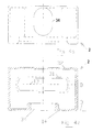
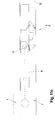
- FIG. 1 shows an interchangeable container 1 according to the invention in a side view, in the supported state.
- the support legs 7 are in their vertical position folded down, and by means of the oblique to the transverse median plane 18 towards above struts 9 positively secured against folding away.
- the length of the strut 9 and its attachment point on Support leg 7 chosen so that after loosening the connection between the strut 9th and the bottom 8 of the interchangeable container 1, the strut 9 by approximately 130 ° to 140 °, position parallel to the support leg 7 on the inside of the support leg 7 is folded around. When the support leg is folded up, the strut 7 ends with it its free end before the nearest mounting bracket 2.
- the support legs 7 are in the unfolded state as close as possible at the front or rear end 4, 5 of the swap body 1, and result in an optimally large mutual distance in the longitudinal direction and thus a very safe support.
- Figure 2 shows that in this known swap body Support legs 7 are mounted within the mounting brackets 2, 2 ', and the Support legs braced both towards the front ends of the swap body are, as well as in the same direction to move to the rest position be folded away.
- FIG. 3 shows a chassis adapter frame 29 of a truck, trailer or the like. which with corresponding twist locks 30 for receiving two in a row horizontal swap body according to the invention is equipped.
- twistlocks 30 ' present, of which only one in the side view in Figure 3 you can see which one of the two central pairs of twistlocks 30 ' has such a longitudinal distance that on the four twistlocks individual, interchangeable container 1 according to the invention can be placed, whereby there is an approximately central position in the longitudinal direction and thus a optimal weight distribution on the chassis adapter frame 29 results.
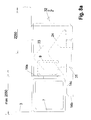
- a conventional, standardized mounting bracket (EN 284) is in the figures 4a in a side view from the outside of the swap body 1 shown, and in Figure 4b in supervision.
- the further opening 34 arranged in the outer wall 14 serves for vertical Rope wrapping of the swap body.
- the distance is from the longitudinal central axis 13 of the housing to its outer surface Outer wall 14, i.e. its half width, at least 89 mm.
- the outer wall 14 of the invention Fastening fitting 2 not consistently formed. Rather protrudes upper part 14a so far inward vertically from the bottom 8 that the support leg in the resting position finds 7 place.
- the support leg is in the range of Fastening fitting 2 released.
- the support leg notch is in the Figures 9 and 9a can be seen. Notching is always required if the outer edge 3 relatively close to the central longitudinal plane 13 of the mounting bracket 2 reaches, and for the unrestricted profile shape of the Support leg 7 is not enough space. This is e.g. when growing from the side hinged side walls 25 required, as shown in Fig. 6.
- Both the cone 23 and the fastening cone are shown 24 in its normal position and in its raised position for locking (24 ').
- the notching of the support leg 7 by a corresponding sheet 16 must be so be designed so that it lies further outside than the entire overhead Cone 23, and so far outside that the mounting cone 24 in the pushed up position not with the notch 16 or for it used, welded onto the notch collides, which from for this reason has bevelled outer edges 15.
- the lower area 14b of the outer wall of the fastening fitting extends up to close to the support leg 7, the upper edge of the lower region 14b serves as a support surface 14c.
- the mounting cone 24 no longer collides with the profile of the Support leg 7, and the support leg 7 only has to be on its inside upper and lower longitudinal edges equipped with chamfered corners 15 in order to collide with the higher path cone 23 in this area avoid.
- the side distance in the solution according to FIG. 8a is between the fastening cone 24 to be inserted and the profile of the support leg 3 so large that the bottom of the mounting bracket 2 immediately below the folded up support leg 7 can run, and there as a horizontal Leg 14c takes over its support.
- the upper area 14 a ends in Figure 8 above the lower edge of the support leg 7, and still above the maximum possible location of an imported Attachment cone 24 or an alternative track cone 23.
- a horizontal leg as a support for the support leg, which preferably extends inwards from the lower region 14b towards the center of the Housing 32 extends out, but also opposite have outward-pointing legs to widen the contact surface can.
- This horizontal leg 14c has no direct connection to the upper area 14a, and also ends before vertical surface of the support leg 7.
- the end edges are 35 of the lower regions 14b of the outer wall, as well as the Base plate 31 is provided with a bevel 35 'to pass through it Bevels provide the greatest possible free space for the deflecting tires of the To create carrier vehicle, with each additional cm gained is valuable.
- the outer wall in its lower region 14b additionally has one in the middle recess 36 pointing downwards from the upper edge.
- the folded up Support leg 7 extends above this recess 36, so that thereby the inner of the mounting bracket always remains accessible.
- the support leg 7 is in the side view with a notch 16 shown.
- the corresponding cross-sectional representation can be seen in FIG. 6.
- Fig. 9a is the support leg 7 with a notch only in the area of Edge 15 shown, as can be seen in the cross-sectional view of FIG. 7.
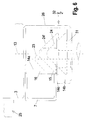
- FIG. 11 shows the oblique strut 9 in the braced state, as well as the associated latching mechanism in the vehicle longitudinal direction viewed in Fig. 11b.
- the one located at the free end of the strut 9 must Mandrel 17, which protrudes backwards from the diagonal strut, with that in the transverse direction the interchangeable container 3 slidable telescopic tube 20 to be locked to secure the strut 9.
- the telescopic tube 20 according to FIG. 11 in the eyelet 21 moved to the right until the mandrel 17 within the Telescopic tube 20 is located. This position is determined by a cam 27 on the inside Secured end of the telescopic tube 20, which is the insertion path of the telescopic tube limited.
- the lower edge of the eyelet 21 for the telescopic tube 20 lies in the same Height with the lower edge of the mounting bracket 2.
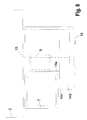
- analog figures 10a, 10b show a solution in which - see Fig. 1b - the oblique strut 9 because of the limitation in the folded up Hibernation by the mounting bracket 2 are not so long can as it is for a good bracing between support leg 7 and the Base frame 8 of the swap body would be desirable.
- the oblique strut 9 is made shorter than the total length of the actual bracing.
- the missing difference is indicated by a Hook plate 19 reached, which strives radially from the telescopic tube 20, and on the free end of the bore or recess for receiving the mandrel 17th having.
- the oblique strut 9 is in the intended Position brought, and then that according to FIG. 10 still in the left Position telescopic tube 20 is initially pivoted so that the Hooking plate 19 from the dashed, approximately horizontal position pivoted below, as shown in Fig. 10a.
- the swivel angle can by an additional stop cam 22 on the bottom group 8 of the Swap bodies are limited.
- the telescopic tube 20 is shifted to the right according to FIG. 10b, whereby the hooking plate 19 slides over the mandrel 17 and the cam 27th of the telescopic tube 20 in the slot 28 of the eyelet 21, whereby a torque and bending bracing is achieved.
- the arrangement of the telescopic tube and also the swivel angle limitation of the Hooking plate 19 are chosen so that there is sufficient space for the existing carrier vehicles is given.
- the support legs 7 are so long that the support height 10 from the lower edge of the Bottom 8 of the swap body 1 to the ground is at least 102 cm.
Landscapes
- Engineering & Computer Science (AREA)
- Mechanical Engineering (AREA)
- Transportation (AREA)
- Pallets (AREA)
- Pharmaceuticals Containing Other Organic And Inorganic Compounds (AREA)
Claims (15)
- Bennes interchangeables pour camions et similaires aveccaractérisée en ce quequatre ferrures de fixation (2, 2') dans respectivement sur la zone externe du fond de la benne interchangeable (1),les ferrures de fixation avant (2) présentant le même déport (6) depuis l'extrémité avant (4) que les ferrures de fixation arrière (2') depuis l'extrémité arrière (5),la benne interchangeable (1) présentant quatre pied-supports (7) pivotant de manière symétrique dans la zone externe du fond (8) entre une position verticale de soutien et une position de repos rabattue, pieds qui sont disposés entre les ferrures de fixation (2, 2') et l'extrémité respective la plus proche (4 respectivement 5) de la benne interchangeable.la benne interchangeable présente au maximum la demi-longueur normalisée d'une benne interchangeable normale,le déport (6) est le même que le déport correspondant des bennes interchangeables,les pieds-supports (7) sont rabattus vers le plan médian transversal de la benne interchangeable en position de repos etles pieds-supports (7) en position de repos repliée chevauchent la ferrure de fixation (2, 2') la plus proche dans la zone externe dans le sens longitudinal etla distance vue dans le sens de la longueur entre le bord interne du pied-support (7) relevés en position de repos et l'axe médian longitudinal vertical (13) de la ferrure de fixation (2, 2') est suffisamment grand pour que dans la ferrure de fixation (2, 2'), il reste un espace de fonction suffisant pour le cône de fixation (24) respectivement pour le pivot ferroviaire (23).
- Benne interchangeable selon la revendication 1 caractérisée en ce que la distance vue dans le sens de la longueur entre le pied-support (7) relevé en position de repos et l'axe médian longitudinal vertical (13) de la ferrure de fixation (2, 2') est inférieure à la demi-largeur d'une ferrure de fixation normalisée.
- Benne interchangeable selon la revendication 1 ou 2, caractérisée en ce que la paroi externe (4) de la ferrure de fixation (2, 2'), tournée vers la face externe du fond (8), observée dans sa zone supérieure (14a), n'est pas alignée avec sa zone (14b) inférieure disposée plus à l'extérieur et les zones supérieure et inférieure (14a, 14b) de la paroi externe (14) de la ferrure de fixation (2, 2') ne sont pas reliées du moins partiellement entre elles.
- Benne interchangeable selon la revendication 3, caractérisée en ce que la zone supérieure (14a) et la zone inférieure (14b) sont sensiblement verticales et la zone inférieure (14b) s'étend jusque tout près de la face inférieure du pied-support (7) quand celui-ci est en position de repos.
- Benne interchangeable selon la revendication 3, caractérisée en ce que la zone inférieure (14b) de la paroi externe (14) présente sur son extrémité supérieure un bras (14c) s'étendant sensiblement à l'horizontal qui sert de surface d'application pour le pied-support (7).
- Benne interchangeable selon la revendication 3, caractérisée en ce que la ferrure de fixation (2, 2') présente aucune paroi externe (14) tournée vers la face externe du fond (8) et sensiblement perpendiculaire.
- Benne interchangeable selon l'une des revendications précédentes, caractérisée en ce que le pied-support (7) au moins dans la zone qui chevauche en position de repos la ferrure de fixation (2, 2'), présente une section transversale profilée réduite sur la face interne en regard de la partie supérieure du pied-support (7).
- Benne interchangeable selon la revendication 7, caractérisée en ce que la largeur du pied-support (7) - vue à l'état déplié dans le sens de la longueur de la benne interchangeable - est réduite sur toute l'extension longitudinale par rapport à la zone supérieure.
- Benne interchangeable selon la revendication 8, caractérisée en ce que le profilé sensiblement quadrangulaire du pied(support (7) est biseauté dans la zone inférieure chevauchant la ferrure de fixation (2, 2') au moins dans le coin (15) dirigé à l'encontre du cône de fixation dans la ferrure de fixation en bas vers l'intérieure.
- Benne interchangeable selon l'une des revendications précédentes, caractérisée en ce qu'en vue latérale de la benne interchangeable, la ferrure de fixation présente au moins sur la face tournée vers la jambe de force inclinée (9) une paroi latérale (33) qui se trouve dans la partie supérieure plus près du milieu de la ferrure de fixation (2) que dans la zone inférieure.
- Benne interchangeable selon la revendication 10, caractérisée en ce que la paroi latérale (33) s'étend verticalement dans la partie supérieure et s'étend de manière inclinée vers l'extérieur et en ce que l'orientation de la paroi latérale '33) s'étendant de manière inclinée vers l'extérieure est placée si bas qu'il y a de la place dans l'espace supérieure pour l'extrémité libre se terminant en pointe de la jambe de force inclinée (9) et dans l'espace inférieure pour le cône de fixation (24).
- Benne interchangeable selon l'une des revendications précédentes, caractérisée en ce que la zone inférieure (14b) de la paroi externe (14) présente depuis le bord supérieur vers le bas un évidemment (36) qui permet en dessous du pied-support (7) un accès à l'intérieur de la ferrure de fixation (2) quand le pied-support (7) est relevé en position de repos.
- Benne interchangeable selon l'une des revendications précédentes, caractérisée en ce que la jambe de force (9) présente sur son extrémité libre un mandrin (17) faisant saillie à l'intérieur vers l'arrière en dessous de la benne interchangeable qui peut être fixé en étant poussé dans une ouverture ou évidemment d'un composant fixé dans le sens transversal de la benne interchangeable.
- Benne interchangeable selon la revendication 14, caractérisée en ce que l'évidemment de la cavité se trouve dans l'extrémité en face avant d'un tube télescopique (20) qui est coulissant dans un manchon (21) relié fixement au fond (8) de la benne interchangeable.
- Benne interchangeable selon la revendication 14, caractérisée en ce que l'évidemment est disposé dans l'extrémité libre d'une tôle formant crochet (19) faisant saillie radialement du tube télescopique (20), qui est reliée de manière fixe en rotation au tube télescopique (20) et en ce que dans une position angulaire du tube télescopique (20) une came (27) fait saillie radialement qui s'engage dans une fente correspondante (28) du manchon (21) logeant le tube télescopique (20) si la tôle formant crochet (19) est enfilée sur le mandrin (17).
Applications Claiming Priority (2)
| Application Number | Priority Date | Filing Date | Title |
|---|---|---|---|
| DE9416308U | 1994-10-10 | ||
| DE9416308U DE9416308U1 (de) | 1994-10-10 | 1994-10-10 | Wechselbehälter |
Publications (2)
| Publication Number | Publication Date |
|---|---|
| EP0706912A1 EP0706912A1 (fr) | 1996-04-17 |
| EP0706912B1 true EP0706912B1 (fr) | 2000-03-22 |
Family
ID=6914709
Family Applications (1)
| Application Number | Title | Priority Date | Filing Date |
|---|---|---|---|
| EP95115883A Expired - Lifetime EP0706912B1 (fr) | 1994-10-10 | 1995-10-09 | Benne interchangeable |
Country Status (2)
| Country | Link |
|---|---|
| EP (1) | EP0706912B1 (fr) |
| DE (2) | DE9416308U1 (fr) |
Cited By (2)
| Publication number | Priority date | Publication date | Assignee | Title |
|---|---|---|---|---|
| US7914042B2 (en) | 2008-05-13 | 2011-03-29 | Rite-Hite Holding Corporation | Support frame vehicle restraints |
| US8006811B2 (en) | 2007-09-07 | 2011-08-30 | Rite-Hite Holding Corporation | Loading dock wheel restraint comprising a flexible elongate member |
Families Citing this family (6)
| Publication number | Priority date | Publication date | Assignee | Title |
|---|---|---|---|---|
| DE19515022C1 (de) * | 1995-04-24 | 1996-10-31 | Ackermann Fruehauf | Befestigungsvorrichtung für verschiedene Wechselbehälter |
| DE29510075U1 (de) * | 1995-06-29 | 1996-11-07 | Krupp Fördertechnik GmbH, 47226 Duisburg | Tragplattform eines Transportfahrzeugs mit Klemmanordnung |
| FR2754223B1 (fr) * | 1996-10-07 | 1998-12-31 | I M C G | Conteneur pour le transport combine "rail-route" de marchandises, a bequilles escamotables |
| WO1998038115A1 (fr) * | 1997-02-26 | 1998-09-03 | Frank Peter Schmidt | Dispositif de support pour conteneurs ou analogues |
| US6318947B1 (en) * | 1999-01-22 | 2001-11-20 | Rite-Hite Holding Corporation | Pulling-style restraint for a parked swap body |
| DE102023204510A1 (de) * | 2023-05-15 | 2024-11-21 | Zf Friedrichshafen Ag | Modulares Transportsystem zum Transport von Gütern |
Family Cites Families (7)
| Publication number | Priority date | Publication date | Assignee | Title |
|---|---|---|---|---|
| GB820391A (en) * | 1956-07-19 | 1959-09-16 | Jean Ernest Fernand Lion | Improved container for the transportation of various goods |
| DE2003495C3 (de) * | 1970-01-27 | 1973-09-27 | Ackermann Fahrzeugbau, 5600 Wuppertal-Vohwinkel | Lastfahrzeug mit auswechselbarem, mit Stutzen versehenem Aufbau |
| CH579470A5 (fr) * | 1974-04-30 | 1976-09-15 | Buessing & Sohn H | |
| DE4005140A1 (de) * | 1990-02-17 | 1991-08-22 | Gerd Schulz | Stuetze |
| DE59301866D1 (de) * | 1992-08-18 | 1996-04-18 | Alusuisse Lonza Services Ag | Stützfuss für Wechselbehälter |
| DE9319064U1 (de) * | 1993-12-13 | 1994-02-10 | Babelsberger Fahrzeugtechnik GmbH, 14482 Potsdam | Stützbein für Wechselbehälter |
| DE9412884U1 (de) * | 1994-08-10 | 1994-10-06 | Gebr. Hellmann GmbH & Co. KG, 49090 Osnabrück | Fahrzeug mit einem Chassis zur Aufnahme von Wechselaufbauten sowie Container hierzu |
-
1994
- 1994-10-10 DE DE9416308U patent/DE9416308U1/de not_active Expired - Lifetime
-
1995
- 1995-10-09 EP EP95115883A patent/EP0706912B1/fr not_active Expired - Lifetime
- 1995-10-09 DE DE59508038T patent/DE59508038D1/de not_active Expired - Lifetime
Cited By (3)
| Publication number | Priority date | Publication date | Assignee | Title |
|---|---|---|---|---|
| US8006811B2 (en) | 2007-09-07 | 2011-08-30 | Rite-Hite Holding Corporation | Loading dock wheel restraint comprising a flexible elongate member |
| US7914042B2 (en) | 2008-05-13 | 2011-03-29 | Rite-Hite Holding Corporation | Support frame vehicle restraints |
| US8662535B2 (en) | 2008-05-13 | 2014-03-04 | Rite-Hite Holding Corporation | Support frame vehicle restraints |
Also Published As
| Publication number | Publication date |
|---|---|
| DE59508038D1 (de) | 2000-04-27 |
| EP0706912A1 (fr) | 1996-04-17 |
| DE9416308U1 (de) | 1995-01-26 |
Similar Documents
| Publication | Publication Date | Title |
|---|---|---|
| DE2731386C2 (fr) | ||
| EP0746490A1 (fr) | Chariot de nettoyage a remorque | |
| EP2185382A1 (fr) | Dispositif de fixation d'un conteneur sur la plate-forme d'un véhicule de transport | |
| DE3719730A1 (de) | Klappsitz | |
| DE4335456C2 (de) | Lastkraftwagen für den Transport von Gütern | |
| EP0706912B1 (fr) | Benne interchangeable | |
| DE8807264U1 (de) | Tankcontainer | |
| DE2515955A1 (de) | Motorverkleidung fuer ein fahrzeug | |
| DE102015113283A1 (de) | Baukasten zum Erstellen verschiedener Wechselrahmen für Nutzfahrzeuge sowie daraus hergestellter Wechselrahmen | |
| DE29801555U1 (de) | Aufbau für ein Transportfahrzeug | |
| DE4117631A1 (de) | Stuetzbein | |
| DE8904509U1 (de) | Fahrzeug für den Transport von Wechselpritschen | |
| EP1975044B1 (fr) | Rancher pour structure de véhicule utilitaire | |
| EP1900892B1 (fr) | Verrou à barre rotative | |
| DE69120987T2 (de) | Türverriegelung für Behälter | |
| EP1847447B1 (fr) | Ranche pour l'ouverture de chargement d'une construction automobile | |
| DE102005050928B4 (de) | Fahrgestell für Container, Aufbauten und dergleichen Ladungsbehälter | |
| EP3578416B1 (fr) | Dispositif de sécurisation du chargement | |
| DE19859856C2 (de) | Hub- und Fahreinheit | |
| DE19515022C1 (de) | Befestigungsvorrichtung für verschiedene Wechselbehälter | |
| DE9316693U1 (de) | Wechselpritsche | |
| EP1409373A1 (fr) | Mecanisme de verrouillage pour recipients, en particulier pour conteneurs | |
| DE102024126924A1 (de) | Faltbarer Anhänger | |
| DE9004986U1 (de) | Lagereinrichtung eines Spriegels | |
| DE2732700A1 (de) | Vorrichtung an lastwagen mit ladeflaeche, seitenwaenden und an diesen verriegelbaren stuetzen |
Legal Events
| Date | Code | Title | Description |
|---|---|---|---|
| PUAI | Public reference made under article 153(3) epc to a published international application that has entered the european phase |
Free format text: ORIGINAL CODE: 0009012 |
|
| AK | Designated contracting states |
Kind code of ref document: A1 Designated state(s): DE FR GB IT NL |
|
| 17P | Request for examination filed |
Effective date: 19960619 |
|
| RAP1 | Party data changed (applicant data changed or rights of an application transferred) |
Owner name: WIHAG NUTZFAHRZEUGTECHNIK GESELLSCHAFT MIT BESCHRA |
|
| 17Q | First examination report despatched |
Effective date: 19971104 |
|
| GRAG | Despatch of communication of intention to grant |
Free format text: ORIGINAL CODE: EPIDOS AGRA |
|
| GRAG | Despatch of communication of intention to grant |
Free format text: ORIGINAL CODE: EPIDOS AGRA |
|
| GRAH | Despatch of communication of intention to grant a patent |
Free format text: ORIGINAL CODE: EPIDOS IGRA |
|
| GRAH | Despatch of communication of intention to grant a patent |
Free format text: ORIGINAL CODE: EPIDOS IGRA |
|
| GRAA | (expected) grant |
Free format text: ORIGINAL CODE: 0009210 |
|
| AK | Designated contracting states |
Kind code of ref document: B1 Designated state(s): DE FR GB IT NL |
|
| PG25 | Lapsed in a contracting state [announced via postgrant information from national office to epo] |
Ref country code: IT Free format text: LAPSE BECAUSE OF FAILURE TO SUBMIT A TRANSLATION OF THE DESCRIPTION OR TO PAY THE FEE WITHIN THE PRESCRIBED TIME-LIMIT;WARNING: LAPSES OF ITALIAN PATENTS WITH EFFECTIVE DATE BEFORE 2007 MAY HAVE OCCURRED AT ANY TIME BEFORE 2007. THE CORRECT EFFECTIVE DATE MAY BE DIFFERENT FROM THE ONE RECORDED. Effective date: 20000322 Ref country code: GB Free format text: LAPSE BECAUSE OF FAILURE TO SUBMIT A TRANSLATION OF THE DESCRIPTION OR TO PAY THE FEE WITHIN THE PRESCRIBED TIME-LIMIT Effective date: 20000322 |
|
| REF | Corresponds to: |
Ref document number: 59508038 Country of ref document: DE Date of ref document: 20000427 |
|
| ET | Fr: translation filed | ||
| GBV | Gb: ep patent (uk) treated as always having been void in accordance with gb section 77(7)/1977 [no translation filed] |
Effective date: 20000322 |
|
| K2C3 | Correction of patent specification (complete document) published |
Effective date: 20000322 |
|
| NLR4 | Nl: receipt of corrected translation in the netherlands language at the initiative of the proprietor of the patent | ||
| PLBE | No opposition filed within time limit |
Free format text: ORIGINAL CODE: 0009261 |
|
| STAA | Information on the status of an ep patent application or granted ep patent |
Free format text: STATUS: NO OPPOSITION FILED WITHIN TIME LIMIT |
|
| 26N | No opposition filed | ||
| PGFP | Annual fee paid to national office [announced via postgrant information from national office to epo] |
Ref country code: NL Payment date: 20021017 Year of fee payment: 8 Ref country code: FR Payment date: 20021017 Year of fee payment: 8 |
|
| PG25 | Lapsed in a contracting state [announced via postgrant information from national office to epo] |
Ref country code: NL Free format text: LAPSE BECAUSE OF NON-PAYMENT OF DUE FEES Effective date: 20040501 |
|
| PG25 | Lapsed in a contracting state [announced via postgrant information from national office to epo] |
Ref country code: FR Free format text: LAPSE BECAUSE OF NON-PAYMENT OF DUE FEES Effective date: 20040630 |
|
| NLV4 | Nl: lapsed or anulled due to non-payment of the annual fee |
Effective date: 20040501 |
|
| REG | Reference to a national code |
Ref country code: FR Ref legal event code: ST |
|
| PGFP | Annual fee paid to national office [announced via postgrant information from national office to epo] |
Ref country code: DE Payment date: 20140915 Year of fee payment: 20 |
|
| REG | Reference to a national code |
Ref country code: DE Ref legal event code: R071 Ref document number: 59508038 Country of ref document: DE |