EP0706918A2 - Dispositif anti-vol pour semiremorques - Google Patents
Dispositif anti-vol pour semiremorques Download PDFInfo
- Publication number
- EP0706918A2 EP0706918A2 EP95115224A EP95115224A EP0706918A2 EP 0706918 A2 EP0706918 A2 EP 0706918A2 EP 95115224 A EP95115224 A EP 95115224A EP 95115224 A EP95115224 A EP 95115224A EP 0706918 A2 EP0706918 A2 EP 0706918A2
- Authority
- EP
- European Patent Office
- Prior art keywords
- housing
- king pin
- recess
- locking
- closed position
- Prior art date
- Legal status (The legal status is an assumption and is not a legal conclusion. Google has not performed a legal analysis and makes no representation as to the accuracy of the status listed.)
- Withdrawn
Links
- 239000007787 solid Substances 0.000 claims description 6
- 230000007797 corrosion Effects 0.000 claims description 5
- 238000005260 corrosion Methods 0.000 claims description 5
- -1 polytetrafluoroethylene Polymers 0.000 claims description 3
- 229920001343 polytetrafluoroethylene Polymers 0.000 claims description 3
- 239000004810 polytetrafluoroethylene Substances 0.000 claims description 3
- 239000000314 lubricant Substances 0.000 claims description 2
- 230000008878 coupling Effects 0.000 description 6
- 238000010168 coupling process Methods 0.000 description 6
- 238000005859 coupling reaction Methods 0.000 description 6
- 230000000875 corresponding effect Effects 0.000 description 3
- 238000005553 drilling Methods 0.000 description 3
- 238000004519 manufacturing process Methods 0.000 description 2
- 229910000851 Alloy steel Inorganic materials 0.000 description 1
- 229910000746 Structural steel Inorganic materials 0.000 description 1
- 239000011248 coating agent Substances 0.000 description 1
- 238000000576 coating method Methods 0.000 description 1
- 238000009833 condensation Methods 0.000 description 1
- 230000005494 condensation Effects 0.000 description 1
- 230000000694 effects Effects 0.000 description 1
- 230000001050 lubricating effect Effects 0.000 description 1
- 238000012423 maintenance Methods 0.000 description 1
- 239000006223 plastic coating Substances 0.000 description 1
Images

Classifications
-
- B—PERFORMING OPERATIONS; TRANSPORTING
- B62—LAND VEHICLES FOR TRAVELLING OTHERWISE THAN ON RAILS
- B62D—MOTOR VEHICLES; TRAILERS
- B62D53/00—Tractor-trailer combinations; Road trains
- B62D53/04—Tractor-trailer combinations; Road trains comprising a vehicle carrying an essential part of the other vehicle's load by having supporting means for the front or rear part of the other vehicle
- B62D53/08—Fifth wheel traction couplings
- B62D53/0842—King pins
- B62D53/085—King pins fitted with anti-coupling devices, pivotal or retractable king pins, e.g. to prevent theft
Definitions
- the invention relates to a device for securing the trailer of a semi-trailer.
- the king pin is a downward projection of the trailer with a circular cross section and standardized dimensions, which has a substantially cylindrical, upper part and a lower, thicker, disc-shaped part.
- the lower part has a larger diameter than the upper section.
- the king pin fits exactly in the recess in the coupling device of the tractor.
- the object of the present invention is to provide a device which can be used to prevent the entire trailer from being stolen.
- Preventing in this context means that a thief needs at least some time and tools to solve the theft protection. However, the time it takes to break out, if it takes too long, is a factor preventing a thief from stealing a trailer because the risk of being discovered is too great.
- an anti-theft device which has a housing which at least partially surrounds the king pin of the trailer and which is provided with at least one locking means which can be moved between a closed position and a loose position and which can be brought into engagement with the upper part of the king pin and delimits a free space in the closed position, the clear width of which is greater than or equal to the outer diameter of the upper part of the king pin and at least in one place smaller than the outer diameter of the lower enlarged part of the king pin, so that the device in the closed position is not removed from the king pin can.
- the king pin is blocked for inclusion in the receiving coupling of the tractor, since the specific dimensions of the king pin are changed.
- the closure means in the closed position by at least one Lock is lockable.
- the anti-theft device can then only be removed with the appropriate key.
- the lock would have to be broken open, causing noise on the one hand.
- the thief needs some time to break the fuse.
- the housing has two housing halves which are connected to one another in an articulated manner as the closure means.
- the two halves of the housing act like a clamp, which are placed around the cylindrical part of the kingpin.
- eyelets and / or bolts may be locked by means of a conventional padlock.
- the articulated housing halves are provided with at least one projection, so that the housing halves with the projection in the closed position limit a free space, the clear width of which is greater than or equal to the diameter of the upper part and less than that lower, thick part of the kingpin.
- the housing halves can be made more solid, which makes it difficult to break open violently.
- the housing has at least one recess, the smallest clear width of which is greater than or equal to the largest diameter of the king pin, and the closure means is designed as at least one projection which can be moved into the recess.
- This training has the advantage that the anti-theft device has no moving parts in such a way that a direct approach to Offer to break open from the outside, for example with a crowbar.
- the projection movable into the recess can, for example, be designed as a simple locking pin, which is expediently actuated via a cylinder lock.
- the closure means is thus covered by the housing, and a targeted attachment of break-open or drilling tools is not possible.
- the housing has at least one recess, the smallest clear width of which is greater than or equal to the largest diameter of the king pin, and the closure means is designed as a rotatably mounted disc in the housing, which is provided with a radially outward projection that engages in the recess in the closed position.
- the anti-theft device is designed in the form of a sleeve which can be attached to the king pin more or less without play below the trailer. Any tools, such as crowbars, saws and the like, then have no or only an unfavorable starting point, which makes it considerably more difficult to remove the anti-theft device by force.
- the housing has at least one recess the smallest clear width of which is greater than or equal to the largest diameter of the king pin
- the closure means is designed as a rotatably mounted locking disk which has a recess which is eccentric to the axis of rotation and whose clear width is greater than or equal to the largest diameter of the king pin, and which is aligned with the recess of the housing in the loose position, wherein a rotation of the locking disk into the closed position displaces the recess relative to the recess of the housing and is at least partially covered by the housing.
- the rotatable locking disk has an actuating element which has at least one predetermined breaking point.
- the predetermined breaking point is designed so that the locking device, for example the locking bolt of the locking cylinder, can withstand greater loads.
- the actuating element breaks off, so that even when the lock is opened, the anti-theft device can only be opened with difficulty and removed from the kingpin.
- the housing has two disk-shaped plates, each with a recess, the smallest clear width of which is greater than or equal to the largest diameter of the kingpin, which are connected to one another by at least one axial projection, so that a substantially annular groove between the plates is present in which the locking disc with the eccentric recess is rotatably mounted.
- the locking disk can be provided on its circumference with at least one lever which projects through the housing wall through a slot-like groove which runs partially along the circumference of the housing.
- the locking disk has at least one recess into which at least one locking pin engages, so that rotation of the locking disk is prevented.
- the recess can run radially, axially or at a different angle to the locking disk.
- a locking cylinder can then be used to close the device, which is designed, for example, as a pressure locking cylinder, the locking pin of which can be actuated in a known manner and can engage in this recess.
- the plates may be welded together. Furthermore, it is also possible that the plates are screwed together, the screws being accessible only from one flat side of the housing, so that in the installed position the screws are covered by the side of the trailer facing the kingpin. In this embodiment, too, the housing cannot be opened in the closed position and in the attached position.
- At least the movable means prefferably be provided with a corrosion-resistant layer.
- This has the advantage that corrosion of the moving parts is avoided even in bad weather conditions and when the trailer is parked for a longer period of time, so that the anti-theft device can always be easily opened properly.
- At least the movable means may be provided with a layer containing solid lubricant. This further increases the functional reliability of the device in an advantageous manner.
- the desired properties with regard to the lubricating effect and the corrosion resistance can be achieved by a layer of polytetrafluoroethylene, which is applied in a known manner, for example to the closure means.
- an anti-theft device provides an effective immobilizer or towing lock for a trailer.
- it is a purely mechanical device, so that no electrical energy is required, which is usually not available on semitrailers anyway or only in a limited amount.
- a battery-operated warning buzzer inside the housing, which is activated when an attempt is made to open it violently, so that the perpetrators could be deterred by the noise. It should be ensured, however, that the buzzer is louder than the engine noise of the diesel engine of a tractor, otherwise the buzzer could easily be drowned out.
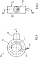
- an anti-theft device 10 for the semi-trailer of a semitrailer is shown, which at least partially surrounds the kingpin of the coupling device of the semi-trailer, so that an unauthorized coupling of a tractor to the semi-trailer is not possible.
- the kingpin is not shown in the drawing, since it is a generally known element for coupling a trailer to a tractor, which also has standardized dimensions.
- the king pin has an upper, essentially cylindrical part, which is adjoined on the lower side by a substantially disk-shaped part which has a larger diameter than the upper part. 4 and 6, the king pin 11 is shown by dashed lines.
- the anti-theft device 10 has an essentially cylindrical housing 12.
- the housing 12 is provided on its two flat sides 13, 14 each with a preferably circular recess 15, 16, the dimensions of which are dimensioned such that the smallest clear width is greater than or at least as large as the largest diameter of the king pin 11. It is therefore possible to put the housing over the king pin 11.
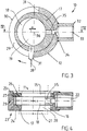
- a locking disc 17 is rotatably mounted about an axis 36 running parallel to the longitudinal axis of the kingpin.
- the locking disc 17 also has on its flat side a preferably circular and continuous recess 18, the dimensions of which are also dimensioned such that the smallest clear width is greater than or at least the same size as the largest diameter of the king pin 11.
- the recess 18 is arranged on the locking disc 17 by a dimension a eccentrically to the axis of rotation 36.
- the arrangement is such that the recess 18 in the loose position (FIGS. 5 and 6) is aligned with the recesses 15, 16 of the housing 12 by a corresponding rotation of the locking disk 17, so that a passage 19 is formed runs parallel to the longitudinal axis of the king pin and its smallest clear width is greater than or at least the same size as the diameter of the lower end 21 of the king pin.
- the eccentric arrangement of the recess 18 on the locking disk 17 reduces the cross section of the passage 19 in the region above the lower end of the king pin, so that the smallest clear width is smaller than the largest diameter of the king pin 11 and at least the same is the same as the diameter of the upper section 20 of the king pin 11.
- the locking washer is therefore on the lower portion of the king pin, so that the anti-theft device 10 can no longer be removed from the king pin.
- the locking disk 17 is rotatably mounted in an annular groove 22 within the housing 12.
- the housing 12 has a bottom element 23 with a U-shaped cross section, the bottom 24 of which is provided with the lower recess 16.
- the clear width of the annular upper part 25 of the base element 23 is slightly larger than the diameter of the locking disk 17.
- the base element 23 is closed from above by an annular cover 26, in which the upper recess 15 is arranged.
- the cover 26 and the base element 23 are connected to one another in such a way that, on the one hand, the respective cutouts 15, 16 are aligned with one another and, on the other hand, the height of the groove 22 formed thereby has a height which is at least as high as the thickness of the Locking disc 17 is so that the latter can be easily rotated within the groove 22.
- the base element 23 has a correspondingly dimensioned shoulder 27 on which the cover 26 is supported.
- the locking disk 17 and the housing 12 run essentially concentrically to one another, while the cutouts 15, 16 run eccentrically to the axis of symmetry of the housing. This can simplify production. In particular, it is not necessary to arrange the recess for receiving the locking disk 17 eccentrically with respect to the housing.
- the cover 26 can in principle be connected to the base element 23 in any manner.
- the cover 26 is welded to the base element 23 in order to bring about a particularly firm connection.
- the cover 26 is screwed to the base element 23.
- the screws are only accessible from one side, namely the side that is hidden by the trailer in the installed position. Unauthorized opening of the housing is therefore not possible when the anti-theft device is attached, while opening, for example for maintenance purposes, remains possible when the anti-theft device is removed.
- a lever 28 is provided on the circumferential side of the locking disk 17, with which the locking disk 17 can be rotated.
- the arrangement is such that the lever 28 extends through a slot-shaped groove 29 which is arranged on the cylindrical outer wall of the housing 12 and extends from the annular groove 22 to the outer surface 30 of the housing 12.
- the slot-shaped groove 29 extends over approximately 180 ° to 200 ° along the circumference, so that the ends 31 of the groove 29 simultaneously represent stops for limiting the rotary movement for the locking disk 17.
- the lever can but can also be guided through an axially extending annular groove and aligned axially downwards accordingly.
- the housing 12 is provided on its side opposite the slot groove 29 with a radially extending projection 32, in which a cylinder lock 33 is arranged and fastened.
- the functioning of a cylinder lock and its attachment are generally known and therefore do not need to be explained in more detail.
- the cylinder lock 33 is designed as a plug lock, the locking bolt 34 cooperating in the closed position with a recess 35 which is arranged on the circumference of the locking disc 17. In the closed position, the locking disc can therefore be fixed, so that the anti-theft device can only be opened with the appropriate key for the cylinder lock. It can also be provided that the locking disc has an axially extending recess and the projection carrying the cylinder lock extends axially downward.
- the anti-theft device 10 is pushed in its loose position (FIGS. 3 and 4) from below onto the king pin, for example, until it touches the upper limit of the king pin. Then, by rotating the locking disk 17 by means of the lever 28, the cross section of the passage 19 formed by the cutouts 15, 16 and 18 in the area of the locking disk 17 is reduced in such a way that the anti-theft device is no longer removed from the kingpin can. In the closed position (FIGS. 5 and 6), the locking disc 17 can then be locked by the locking bolt 34 of the cylinder lock 33. Basically, it is possible that the locking pin is pressed into the recess by a spring when the closed position is reached. Under the harsh operating conditions, however, it is useful if the The locking pin can only be actuated via the cylinder lock.
- the closure means which is designed as a rotatable locking disk, is difficult or impossible to recognize from the outside, so that deliberate acts of breaking open can be made much more difficult or even prevented.
- the entire device In order to avoid a violent breakup, it is advisable to make the entire device as solid as possible. As shown in the drawing, this can be brought about by thick walls of the housing and by a solid locking disk.
- the housing and the locking disc can for example consist of high-strength structural steel or possibly also of an alloy steel which is, for example, corrosion-resistant.
- the locking disk or a closure means designed in another way can be coated, for example, with polytetrafluoroethylene or another plastic coating with corresponding properties in order to achieve an improved sliding effect.
- the dimensions of the anti-theft device are such that the lower part of the kingpin protrudes from the bottom of the device. It is of course also possible that the housing is extended downwards and is closed, for example, by a bottom cover. This has the advantage that the locking disc is no longer accessible from below, so that the possible use of breaking or drilling tools is no longer possible. Furthermore, since the movable elements, in particular their dimensions, cannot be recognized in this case, targeted drilling can be prevented or made considerably more difficult. To allow condensation or the like to drain, it is expedient to provide the bottom cover with at least one drain hole.
- the extent of the eccentricity a is basically arbitrary. However, it is expedient if the eccentricity a is selected such that the anti-theft device 10 is held on the king pin essentially without play. This can also make an approach of break-open tools more difficult. This means that the eccentricity a has an extent which corresponds approximately to half the difference between the diameter of the upper and that of the lower section 20, 21 of the king pin 11. The height of the housing 12 can essentially correspond to the height of the cylindrical part 20 of the king pin 11 with the smaller diameter.
Landscapes
- Engineering & Computer Science (AREA)
- Chemical & Material Sciences (AREA)
- Combustion & Propulsion (AREA)
- Transportation (AREA)
- Mechanical Engineering (AREA)
- Lock And Its Accessories (AREA)
Applications Claiming Priority (2)
| Application Number | Priority Date | Filing Date | Title |
|---|---|---|---|
| DE4435880 | 1994-10-07 | ||
| DE19944435880 DE4435880C1 (de) | 1994-10-07 | 1994-10-07 | Diebstahlsicherung |
Publications (2)
| Publication Number | Publication Date |
|---|---|
| EP0706918A2 true EP0706918A2 (fr) | 1996-04-17 |
| EP0706918A3 EP0706918A3 (fr) | 1996-10-16 |
Family
ID=6530209
Family Applications (1)
| Application Number | Title | Priority Date | Filing Date |
|---|---|---|---|
| EP95115224A Withdrawn EP0706918A3 (fr) | 1994-10-07 | 1995-09-27 | Dispositif anti-vol pour semiremorques |
Country Status (2)
| Country | Link |
|---|---|
| EP (1) | EP0706918A3 (fr) |
| DE (1) | DE4435880C1 (fr) |
Cited By (2)
| Publication number | Priority date | Publication date | Assignee | Title |
|---|---|---|---|---|
| WO2005028290A1 (fr) * | 2003-09-03 | 2005-03-31 | Georg Fischer Verkehrstechnik Gmbh | Sellette d'attelage equipee d'un dispositif antivol |
| DE202012104096U1 (de) | 2012-10-24 | 2012-11-28 | Bernd Engelking | Diebstahlsicherung für Sattelschlepperauflieger |
Family Cites Families (18)
| Publication number | Priority date | Publication date | Assignee | Title |
|---|---|---|---|---|
| US2656706A (en) * | 1951-05-08 | 1953-10-27 | Trail Lock Corp | Lock collar for trailer kingpins |
| US2785564A (en) * | 1955-09-20 | 1957-03-19 | Rossi Carrato | Trailer hitch lock |
| US3009421A (en) * | 1957-07-11 | 1961-11-21 | Thompson Ramo Wooldridge Inc | Slipper type transmission pump |
| US3269159A (en) * | 1964-08-17 | 1966-08-30 | Chalmers C Young | Theft prevention device for trailers |
| US3706211A (en) * | 1971-03-04 | 1972-12-19 | Alvin L Owen | Security device |
| US3744284A (en) * | 1972-02-22 | 1973-07-10 | C Waldenstrom | Tamper-proof security device |
| US3922897A (en) * | 1974-12-05 | 1975-12-02 | Thorwald J Mickelson | Semitrailer king pin securing device |
| DE2503915A1 (de) * | 1975-01-31 | 1976-08-05 | Jost Werke Gmbh | Diebstahl-schutzvorrichtung fuer koenigszapfen |
| GB1572792A (en) * | 1977-01-17 | 1980-08-06 | Powell & Jones Ltd | Anti-theft device |
| GB2049587B (en) * | 1979-05-17 | 1983-03-23 | Dennic Eng Ltd | Locking devices for tractor-trailer connection |
| DE3308519A1 (de) * | 1983-03-10 | 1984-09-13 | Karlo 2000 Hamburg Kuzmanov | Diebstahl-sicherheitsvorrichtung fuer abgestellte sattelaufbauten (sattelanhaenger) |
| GB2165507B (en) * | 1984-10-10 | 1988-10-19 | Keith Jeffrey | Security device |
| US4882921A (en) * | 1988-12-01 | 1989-11-28 | Frank Wopinski | King pin lock |
| GB2240076A (en) * | 1990-01-19 | 1991-07-24 | Archibald Grant | Security device for an articulated lorry |
| GB2248810B (en) * | 1990-09-01 | 1994-06-22 | Trailer Lock Dev Ltd | King-pin disabling device |
| FR2672632A1 (fr) * | 1991-02-13 | 1992-08-14 | Zivanovic Milovoje | Dispositif antivol de semi-remorque. |
| US5297407A (en) * | 1993-02-22 | 1994-03-29 | Tarr Merwin E | Trailer locking apparatus |
| EP0622292A1 (fr) * | 1993-04-28 | 1994-11-02 | Norman John Hemmingsley | Système de sécurité pour remorques |
-
1994
- 1994-10-07 DE DE19944435880 patent/DE4435880C1/de not_active Expired - Fee Related
-
1995
- 1995-09-27 EP EP95115224A patent/EP0706918A3/fr not_active Withdrawn
Non-Patent Citations (1)
| Title |
|---|
| None |
Cited By (3)
| Publication number | Priority date | Publication date | Assignee | Title |
|---|---|---|---|---|
| WO2005028290A1 (fr) * | 2003-09-03 | 2005-03-31 | Georg Fischer Verkehrstechnik Gmbh | Sellette d'attelage equipee d'un dispositif antivol |
| US8371600B2 (en) | 2003-09-03 | 2013-02-12 | Saf-Holland Verkehrstechnik Gmbh | Fifth wheel with anti-theft protection device |
| DE202012104096U1 (de) | 2012-10-24 | 2012-11-28 | Bernd Engelking | Diebstahlsicherung für Sattelschlepperauflieger |
Also Published As
| Publication number | Publication date |
|---|---|
| DE4435880C1 (de) | 1996-03-21 |
| EP0706918A3 (fr) | 1996-10-16 |
Similar Documents
| Publication | Publication Date | Title |
|---|---|---|
| DE3622361C2 (fr) | ||
| EP2076643A1 (fr) | Dispositif pour actionner une serrure dans la porte ou le hayon d'un véhicule automobile | |
| EP0752044B1 (fr) | Serrure equipee d'un barillet de fermeture, destinee en particulier aux vehicules automobiles | |
| DE3626014C2 (fr) | ||
| DE1678121C3 (de) | VerschluBgehäuse mit Drehfalle und an dieser angreifenden Sperrklinke eines Kfz-Türverschlusses | |
| DE69505987T2 (de) | Kraftfahrzeug-sicherungsvorrichtung | |
| EP3162677A1 (fr) | Sicherungseinrichtung | |
| DE4313570C2 (de) | Sicherheitsverriegelung für Fahrzeugabdeckungen | |
| DE3905183A1 (de) | Diebstahlsicherung fuer kraftfahrzeuge | |
| DE4435880C1 (de) | Diebstahlsicherung | |
| EP0851823B1 (fr) | Semi-remorque avec antivol | |
| EP0095146B1 (fr) | Dispositif de verrouillage pour arbre de direction de véhicule | |
| DE69006180T2 (de) | Kappe mit einem Diebstahlsicherungsschloss für ein Befestigungselement. | |
| EP1922459A1 (fr) | Cylindre de fermeture pour fonctions pouvant notamment etre mises en oeuvre dans des vehicules | |
| DE102009030001A1 (de) | Schließvorrichtung, insbesondere Bootsschloss für Außenbordmotoren | |
| DE69916193T2 (de) | Lenkschloß für ein Kraftfahrzeug mit Mitteln zur Fixierung eines Lenkschloßmechanismus | |
| DD230842A1 (de) | Vorrichtung zum absperren des handbremshebels von kraftfahrzeugen | |
| DE3537956C2 (fr) | ||
| DE1238782B (de) | Diebstahlsicherung fuer Kraftfahrzeuganhaenger | |
| DE69401367T2 (de) | Diebstahlsicherung für ein Fahrzeug | |
| DE60119364T2 (de) | Befestigungsvorrichtung | |
| DE202012104096U1 (de) | Diebstahlsicherung für Sattelschlepperauflieger | |
| EP0033936A2 (fr) | Serrure à partie pivotante pour un véhicule, en particulier une bicyclette | |
| DE10355854A1 (de) | Abnehmbare Anhängerkupplung mit obenliegender elektrischer Entriegelung | |
| DE69809478T2 (de) | Verriegelungsvorrichtung |
Legal Events
| Date | Code | Title | Description |
|---|---|---|---|
| PUAI | Public reference made under article 153(3) epc to a published international application that has entered the european phase |
Free format text: ORIGINAL CODE: 0009012 |
|
| AK | Designated contracting states |
Kind code of ref document: A2 Designated state(s): AT BE CH DE DK ES FR GB GR IE IT LI LU MC NL PT SE |
|
| AX | Request for extension of the european patent |
Free format text: LT PAYMENT 951017;LV PAYMENT 951017 |
|
| RAX | Requested extension states of the european patent have changed |
Free format text: LT PAYMENT 951017;LV PAYMENT 951017 |
|
| PUAL | Search report despatched |
Free format text: ORIGINAL CODE: 0009013 |
|
| AK | Designated contracting states |
Kind code of ref document: A3 Designated state(s): AT BE CH DE DK ES FR GB GR IE IT LI LU MC NL PT SE |
|
| AX | Request for extension of the european patent |
Free format text: LT PAYMENT 951017;LV PAYMENT 951017 |
|
| 17P | Request for examination filed |
Effective date: 19970225 |
|
| 17Q | First examination report despatched |
Effective date: 19980520 |
|
| STAA | Information on the status of an ep patent application or granted ep patent |
Free format text: STATUS: THE APPLICATION IS DEEMED TO BE WITHDRAWN |
|
| 18D | Application deemed to be withdrawn |
Effective date: 19981201 |