EP0706924B1 - Servo-moteur de freinage contrÔlé électroniquement et procédé de fonctionnement - Google Patents
Servo-moteur de freinage contrÔlé électroniquement et procédé de fonctionnement Download PDFInfo
- Publication number
- EP0706924B1 EP0706924B1 EP95114883A EP95114883A EP0706924B1 EP 0706924 B1 EP0706924 B1 EP 0706924B1 EP 95114883 A EP95114883 A EP 95114883A EP 95114883 A EP95114883 A EP 95114883A EP 0706924 B1 EP0706924 B1 EP 0706924B1
- Authority
- EP
- European Patent Office
- Prior art keywords
- pressure
- signal
- brake
- brake booster
- prevailing
- Prior art date
- Legal status (The legal status is an assumption and is not a legal conclusion. Google has not performed a legal analysis and makes no representation as to the accuracy of the status listed.)
- Expired - Lifetime
Links
- 238000000034 method Methods 0.000 title claims description 21
- 230000009467 reduction Effects 0.000 claims description 2
- 230000000063 preceeding effect Effects 0.000 claims 6
- 230000004069 differentiation Effects 0.000 claims 3
- 239000003570 air Substances 0.000 description 5
- 238000010586 diagram Methods 0.000 description 5
- 230000000875 corresponding effect Effects 0.000 description 4
- 230000001419 dependent effect Effects 0.000 description 3
- 238000006073 displacement reaction Methods 0.000 description 3
- 230000008569 process Effects 0.000 description 3
- 230000008859 change Effects 0.000 description 2
- 230000002596 correlated effect Effects 0.000 description 2
- 238000009795 derivation Methods 0.000 description 2
- 230000001133 acceleration Effects 0.000 description 1
- 239000012080 ambient air Substances 0.000 description 1
- 238000009530 blood pressure measurement Methods 0.000 description 1
- 230000000994 depressogenic effect Effects 0.000 description 1
- 230000007613 environmental effect Effects 0.000 description 1
- 230000005284 excitation Effects 0.000 description 1
- 230000007274 generation of a signal involved in cell-cell signaling Effects 0.000 description 1
- 230000007246 mechanism Effects 0.000 description 1
- 230000035484 reaction time Effects 0.000 description 1
- 238000004088 simulation Methods 0.000 description 1
Images


Classifications
-
- B—PERFORMING OPERATIONS; TRANSPORTING
- B60—VEHICLES IN GENERAL
- B60T—VEHICLE BRAKE CONTROL SYSTEMS OR PARTS THEREOF; BRAKE CONTROL SYSTEMS OR PARTS THEREOF, IN GENERAL; ARRANGEMENT OF BRAKING ELEMENTS ON VEHICLES IN GENERAL; PORTABLE DEVICES FOR PREVENTING UNWANTED MOVEMENT OF VEHICLES; VEHICLE MODIFICATIONS TO FACILITATE COOLING OF BRAKES
- B60T13/00—Transmitting braking action from initiating means to ultimate brake actuator with power assistance or drive; Brake systems incorporating such transmitting means, e.g. air-pressure brake systems
- B60T13/10—Transmitting braking action from initiating means to ultimate brake actuator with power assistance or drive; Brake systems incorporating such transmitting means, e.g. air-pressure brake systems with fluid assistance, drive, or release
- B60T13/66—Electrical control in fluid-pressure brake systems
- B60T13/72—Electrical control in fluid-pressure brake systems in vacuum systems or vacuum booster units
-
- B—PERFORMING OPERATIONS; TRANSPORTING
- B60—VEHICLES IN GENERAL
- B60T—VEHICLE BRAKE CONTROL SYSTEMS OR PARTS THEREOF; BRAKE CONTROL SYSTEMS OR PARTS THEREOF, IN GENERAL; ARRANGEMENT OF BRAKING ELEMENTS ON VEHICLES IN GENERAL; PORTABLE DEVICES FOR PREVENTING UNWANTED MOVEMENT OF VEHICLES; VEHICLE MODIFICATIONS TO FACILITATE COOLING OF BRAKES
- B60T7/00—Brake-action initiating means
- B60T7/02—Brake-action initiating means for personal initiation
- B60T7/04—Brake-action initiating means for personal initiation foot actuated
- B60T7/042—Brake-action initiating means for personal initiation foot actuated by electrical means, e.g. using travel or force sensors
-
- B—PERFORMING OPERATIONS; TRANSPORTING
- B60—VEHICLES IN GENERAL
- B60Y—INDEXING SCHEME RELATING TO ASPECTS CROSS-CUTTING VEHICLE TECHNOLOGY
- B60Y2400/00—Special features of vehicle units
- B60Y2400/30—Sensors
- B60Y2400/306—Pressure sensors
-
- B—PERFORMING OPERATIONS; TRANSPORTING
- B60—VEHICLES IN GENERAL
- B60Y—INDEXING SCHEME RELATING TO ASPECTS CROSS-CUTTING VEHICLE TECHNOLOGY
- B60Y2400/00—Special features of vehicle units
- B60Y2400/81—Braking systems
Definitions
- the present invention relates to an electronically controlled Brake booster for a road vehicle brake system, with a housing that is a vacuum chamber and one from the vacuum chamber through a movable one Wall has separate working chamber, one electromagnetic actuatable control valve assembly that is movable with the Wall to common relative movement against the Housing is connected, and a sensor that is used for an electronic Control device operating states of the road vehicle brake system recorded and for these operating conditions characteristic signals generated by the control device for generating control signals for the control valve arrangement evaluates.
- DE 41 02 496 A1 describes a brake pressure control device known the force applied to the brake pedal or as a directly correlated variable in hydraulic Brake circuit to measure generated brake pressure at Exceeding a threshold to lock the brake circuit, in which the increased brake pressure was measured.
- the triggering of the emergency braking means that the Master brake lines blocked against the master cylinder have to be and the wheel brakes are valve controlled with the Output pressure of an auxiliary pressure source can be applied.
- the brake pedal has become "hard” and one path-dependent control of the automatic braking process is no longer possible if there is no additional buffer volume are provided which against the master brake cylinder locked wheel brakes by pedaling of the driver can be displaced. Only that would be one Pedal travel simulation possible, based on their timing Another driver request regarding the expected vehicle deceleration recognizable and during further braking would be considered.
- the invention is therefore based on the problem of an electronically Controlled brake booster for a road vehicle brake system of the type mentioned above to further train that the influence of the system-inherent dead times and the rigidity of the hydraulic system or the Brake booster and the mechanical play of the brake pedal mechanism are as low as possible.
- the senor is a pressure sensor designed and recorded at least that in the working chamber prevailing pressure.
- the invention is based on the surprising finding that the pressure in the working chamber depends on the rigidity of the Brake system is independent because the change in pressure only by a relative movement of those displaced by the brake pedal Actuating rod to the housing of the control valve assembly is initiated.
- this movement is over essential sections of brake pedal actuation, in particular at the beginning the path of actuation, not correlated with the axial relative movement of the control valve arrangement the housing of the brake booster, which results from the following Considerations result in:
- a slow actuation of the brake pedal (with increasing Force) for a long period of time can have the same working chamber pressure cause like a quick actuation the brake pedal for a shorter period.
- This is because remember that when you press the brake pedal Control valve is opened so that in the working chamber Air flows in and a displacement of the movable wall causes. Whether the control valve is open for a short time becomes, or only marginally for a long time, is for the inflowing air volume is negligible.
- the postponement of the diaphragm plate when increasing the working chamber volume takes place against the opposing forces in the braking system (Return springs in the brake booster, brakes, Etc.). However, these counterforces increase with increasing Pedal actuation on. Therefore, in the invention by the the pressure measured in the working chamber is the one introduced Work (force applied to the brake pedal integrated via the displacement path linked to the gain factor of the brake booster) using the pressure sensor evaluable.
- the pressure sensor can on or in a fixed wall of the Be arranged housing, or on or in the movable Be arranged on the wall.
- the pressure sensor Detected according to a preferred embodiment of the invention the pressure sensor not only that in the working chamber prevailing absolute pressure but the pressure difference between the pressure prevailing in the vacuum chamber and the pressure prevailing in the working chamber and generates a for this pressure difference characteristic signal for the Control device.
- the pressure sensor detects the pressure difference between that in the ambient atmosphere of the brake booster prevailing pressure and that in the work chamber prevailing pressure and generates one for this pressure difference characteristic signal for the control device.
- the signal generated is independent of the differential pressure measurement of ambient pressure fluctuations, what the further Processing simplified.
- a second one can also be used Pressure sensor outside the housing or in the vacuum chamber be arranged in the surrounding atmosphere of the brake booster pressure or in the pressure chamber prevailing pressure and a for this pressure characteristic signal for the control device generated.
- both the signal with the pressure in the working chamber as well as the signal with the pressure of the environment or the vacuum chamber to the control device passed and there for further processing and control signal generation evaluated.
- the non-derivative can also be used Signal curve are evaluated in order at high pressure values, that are slowly achieved, also an automatic one Trigger braking.
- the threshold can be both be fixed, as well as based on other parameters (e.g. vehicle speed) from a characteristic field be determined.
- the first control signal is preferably dimensioned in such a way that that it creates the maximum possible brake pressure. This can be done without risk as the ABS regulation for it Take care that there is no locking of the wheels is coming.
- the trigger signal can be a vehicle acceleration to be achieved or delay, the speed of a vehicle in front or another signal, that e.g. is generated by a distance radar.
- the vacuum chamber can be used in brake systems that do not Delay value specification by a controller or a Pedal actuation received signal, the brake pressure in the master brake cylinder in a linear relationship the working chamber (difference) pressure used as an auxiliary variable to e.g. to determine the brake pressure. So that can implemented a traction help or an anti-slip control system will.
- FIG. 1 shows a brake booster designated by 10, executed here as a tandem brake booster is.
- the invention can also be used for single brake boosters be used.
- the brake booster 10 shown has an essentially rotationally symmetrical housing 12, in which a (rear) Working chamber 14 and a (front) Vacuum chamber 16 arranged and by a movable Wall 18 related to each other relative to common movement is connected to the housing 12. Acts on the valve 20 the front end of a rod-shaped actuator 22, which in the installed state with a (not shown) Brake pedal of the motor vehicle is connected.
- the power output member 30 is for actuating a Master brake cylinder not shown provided.
- a pressure sensor 32 is arranged in the movable wall 18, which measures the pressure in the working chamber and conducts the signal S 1 representing the pressure (curve) via a line 34 out of the housing of the brake booster 10 to an electronic control unit ECU.
- the electronic control unit ECU is connected to an electromagnet of the control valve arrangement 20 via a line, not further illustrated, so that, controlled by the electronic control unit ECU, the control valve arrangement 20 can be actuated so that the control valve arrangement 20 opens to allow air to flow into the working chamber 14 read or close to separate the working chamber 14 from the ambient atmosphere.
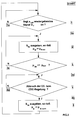
- the excitation or de-excitation of the electromagnet of the control valve arrangement 20 takes place as a function of the signal representing the pressure in the working chamber 14, which signal can be processed in different ways, as illustrated in FIGS. 2 and 3.
- Fig. 2 it is assumed that not only the pressure in the working chamber 14, but also the pressure in the vacuum chamber 16 is measured and signals S 1a , S 1b reflecting these pressure profiles are sent to the electronic control unit ECU via line 34 in Fig. 1 out.
- This common signal is derived in time (differentiated) and compared with a threshold value S threshold (step 2 in FIG. 2). If the derivative signal (dS1 / dt) is smaller than the threshold value S threshold , the process branches back to the start (step 2a in FIG. 2). If the derivative signal (dS1 / dt) is greater than or equal to the threshold value S threshold , a branch is made to step 3 in FIG. 3 (step 2b in FIG. 2).
- the threshold value S threshold can either be constant or can be changed depending on other environmental parameters such as the vehicle speed or the like.
- a characteristic course of the pressure (for example peak, flank or the like) in the working chamber or the rate of pressure rise can also be predetermined and compared with the corresponding measured variable that occurs.
- step 3 in FIG. 2 the electronic control unit ECU outputs a signal S 2a to the electromagnet of the control valve arrangement 20, which causes the control valve arrangement 20 to be actuated so that air flows into the working chamber 14 and triggers assisted (emergency) braking becomes.
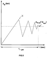
- the brake pressure p B in the hydraulic system is raised to an increased pressure value p Bact , so that an increased brake application takes place.
- the wheels of the vehicle cannot lock, since the ABS control ensures that a maximum brake pressure p Bmax is not exceeded.
- a check as to whether the driver wishes to abort the emergency or target braking is carried out in step 4 of FIG. 2.
- a return signal S r that is generated by a switch in the control valve arrangement 20. Embodiments and details of this switch are described in the most diverse configurations in the previously published post-published application P 44 00 688.8.
- This switch detects a lifting of the driver's foot from the brake pedal and emits a corresponding signal S r . If this signal is not present S r , ie the driver does not want to abort braking, the program run is branched to the beginning of step 3 in FIG. 2 (step 4a in FIG. 2).
- the signal S 2b is output by the electronic control device ECU according to step 5 in FIG. 2 to the electromagnet of the control valve arrangement 20.
- the electromagnet is de-energized or reversed in polarity, so that the control valve arrangement 20 interrupts the air supply into the working chamber 14, as a result of which the brake pressure p B falls back to the normal brake pressure p Bnorm in the hydraulic system of the brake system.
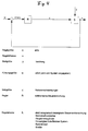
- FIG. 4 schematically shows the control device in order to decelerate the vehicle on the basis of a predetermined vehicle target deceleration value a target with the aid of the arrangement or procedure described above, so as to avoid, for example, the vehicle colliding with an obstacle.
- This pressure difference causes a shift in the movable wall 18 in the sense of a reduction in Volume of the vacuum chamber 16, so that the Power output member 30 in the direction of arrow P (see Fig. 1) is moved.
- the brakes of the Vehicle are operated and the vehicle is thus decelerated becomes.
- This delay can be caused by sensors on the Vehicle wheels are detected and sent to the electronic Control device are reported.
- the elapsed time period t 1ges is the total reaction time of the control system.
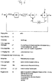
- the cascade control shown in FIG. 6 is proposed according to the invention, in which an inner control loop (RH, S, U2) controls the pressure difference between the working chamber and the vacuum chamber, while the external control loop converts a target deceleration of the vehicle (a target ) specified by the system into an actual vehicle deceleration a motor vehicle such that a corresponding differential pressure or pressure setpoint is generated as a reference variable for the auxiliary controller when a target deceleration signal occurs.
- This can be done, for example, by selecting from a map stored in the electronic control device ECU, whereby an electromagnetic actuation of the control valve arrangement takes place, so that the differential pressure between the working chamber and the vacuum chamber or the pressure in the working chamber adjusts to the desired value.
- Dp to this determined differential pressure target value represents an average pressure value which is able to achieve the required deceleration of the vehicle approached.
- the overall control precisely adjusts to the deceleration setpoint.
- FIG. 7 illustrates the time behavior of this cascade control illustrated in FIG. 6. Obviously, the much shorter time t 2ges is required in order to reach the brake pressure required for the target vehicle deceleration a target . At the beginning of the control cycle, the pressure difference is approximated to the reference variable dp target relatively quickly before the system regulates the reference to the reference variable a target .
Landscapes
- Engineering & Computer Science (AREA)
- Transportation (AREA)
- Mechanical Engineering (AREA)
- Regulating Braking Force (AREA)
- Braking Systems And Boosters (AREA)
- Hydraulic Control Valves For Brake Systems (AREA)
Claims (15)
- Servofrein commandé électroniquement pour un système de freinage de véhicule routier, comprenantun boitier qui présente une chambre de dépression (14) et une chambre de travail (16) séparée de la chambre de dépression (14) par une paroi mobile (18),un système de distribution et de régulation (20) pouvant être actionné électromagnétiquement qui est relié à la paroi-mobile (18) pour se déplacer avec celle-ci relativement au boítier du servofrein, etun capteur (32) qui relève des états de fonctionnement du système de freinage du véhicule routier pour une unité de commande électronique (ECU) et génère des signaux caractéristiques de ces états de fonctionnement que l'unité de commande (ECU) exploite pour générer des signaux de commande (S1a , S1b) pour le système de distribution et de régulation (20),
caractérisé en ce quele capteur est un capteur de pression (32) et relève au moins la pression (pAK) régnant dans la chambre de travail (16). - Servofrein commandé électroniquement selon la revendication 1, caractérisé en ce quele capteur de pression (32) est disposé contre ou dans une paroi fixe du boítier du servofrein.
- Servofrein commandé électroniquement selon la revendication 1, caractérisé en ce quele capteur de pression (32) est disposé contre ou dans la paroi mobile (18).
- Servofrein commandé électroniquement selon l'une quelconque des revendications précédentes, caractérisé en ce quele capteur de pression (32) relève la différence de pression (dp) entre la pression (pUK) régnant dans la chambre de dépression (14) et la pression (pAK) régnant dans la chambre de travail (16) et génère un signal caractéristique de cette différence de pression (dp) pour l'unité de commande (ECU).
- Servofrein commandé électroniquement selon la revendication 2, caractérisé en ce quele capteur de pression (32) relève la différence de pression (dp) entre la pression (pUm) régnant dans l'atmosphère environnant le servofrein (10) et la pression (pAK) régnant dans la chambre de travail (16) et génère un signal caractéristique de cette différence de pression (dp) pour l'unité de commande (ECU).
- Servofrein commandé électroniquement selon la revendication 1, caractérisé en ce queun deuxième capteur de pression est disposé à l'extérieur du boitier du servofrein (10) ou dans la chambre de dépression (14), qui relève la pression (pUm) régnant dans l'atmosphère environnant le servofrein (10) respectivement la pression (pUK) régnant dans la chambre de dépression (14) et génère un signal caractéristique de cette pression (pUm, PUK) pour l'unité de commande (ECU).
- Procédé de fonctionnement d'un système de freinage comprenant un servofrein commandé électroniquement selon l'une quelconque des revendications précédentes, caractérisé par les opérations suivantes consistant à :a) relever la pression (pAK) régnant dans la chambre de travail (16) du servofrein,b) générer un signal caractéristique de la pression (pAK, dp) régnant dans la chambre de travail (16), etc) évaluer le signal (S1) pour générer un signal de commande (S2) pour un système de distribution et de régulation pouvant être actionné électromagnétiquement (20) du servofrein (10), etd) émettre un signal de commande (S2a, S2b) au système de distribution et de régulation (20) relié à la paroi mobile (18) pour se déplacer avec celle-ci relativement au boítier du servofrein qui engendre un actionnement du servofrein (10) dans le sens d'une augmentation ou d'un abaissement d'une pression de freinage (pB).
- Procédé de fonctionnement d'un système de freinage de véhicule selon la revendication 7, caractérisé en ce que l'opération c) consiste de plus à :c1) combiner le signal (S1a) caractéristique de la pression (pAK) régnant dans la chambre de travail (14) avec un signal (S1b) caractéristique de la pression (pUm) régnant dans l'atmosphère environnant le servofrein (10) ou de la pression (pUK) régnant dans une chambre de dépression (14) du servofrein (10) en un signal commun (S1).
- Procédé de fonctionnement d'un système de freinage de véhicule selon la revendication 7 ou 8, caractérisé en ce que l'opération c) consiste de plus à :c2) dériver le signal (S1) par rapport au temps pour obtenir un signal de dérivée (dS1/dt).
- Procédé de fonctionnement d'un système de freinage de véhicule selon la revendication précédente, caractérisé en ce que l'opération c) consiste de plus à :c3) comparer le signal de dérivée (dS1/dt) à une valeur de seuil prédéterminée (Sschwelle).
- Procédé de fonctionnement d'un système de freinage de véhicule selon la revendication précédente, caractérisé en ce que l'opération c) consiste de plus à :c4) générer un premier signal de commande (S2a) dans le cas où le signal de dérivée (dS1/dt) est supérieur ou égal à la valeur de seuil (Sschwelle), le premier signal de commande (S2a) ayant une grandeur telle qu'il provoque un actionnement du servofrein (10) qui génère une autre pression de freinage (pBact), de préférence plus élevée, que celle qui résulterait de la position instantanée d'une pédale de frein reliée au servofrein (10).
- Procédé de fonctionnement d'un système de freinage de véhicule selon la revendication précédente, caractérisé en ce quele premier signal de commande (S2a) a une grandeur telle qu'il fasse générer une pression de freinage la plus grande possible (pBmax).
- Procédé de fonctionnement d'un système de freinage de véhicule selon l'une quelconque des revendications 7 à 12, caractérisé en ce que l'opération c) consiste de plus à :c5) relever une position d'actionnement de la pédale de frein, etc6) générer un signal de retrait (Sr) reproduisant un retrait de la pédale de frein d'une distance d'actionnement prédéterminée.
- Procédé de fonctionnement d'un système de freinage de véhicule selon la revendication précédente, caractérisé par l'opération supplémentaire consistant à :e) émettre un deuxième signal de commande (S2b) au système de distribution et de régulation (20) qui provoque un actionnement du servofrein (10) dans le sens d'un abaissement de la pression de freinage (pB) à une pression de freinage normale (pBnorm) lorsque le signal de retrait (Sr) est présent.
- Procédé de fonctionnement d'un système de freinage de véhicule selon l'une quelconque des revendications de procédé précédentes, caractérisé par l'opération supplémentaire consistant à :f) générer un signal de déclenchement (asoll) indépendant d'un actionnement de la pédale de frein destiné à l'unité de commande électronique (ECU) qui génère en fonction du signal de déclenchement (asoll) un signal (S3) qui provoque un actionnement du servofrein (10) qui engendre une autre décélération du véhicule, de préférence supérieure à la décélération instantanée du véhicule.
Applications Claiming Priority (2)
| Application Number | Priority Date | Filing Date | Title |
|---|---|---|---|
| DE4436297 | 1994-10-11 | ||
| DE4436297A DE4436297C2 (de) | 1994-10-11 | 1994-10-11 | Elektronisch gesteuerter Bremskraftverstärker und Verfahren zu dessen Betrieb |
Publications (2)
| Publication Number | Publication Date |
|---|---|
| EP0706924A1 EP0706924A1 (fr) | 1996-04-17 |
| EP0706924B1 true EP0706924B1 (fr) | 1998-06-17 |
Family
ID=6530483
Family Applications (1)
| Application Number | Title | Priority Date | Filing Date |
|---|---|---|---|
| EP95114883A Expired - Lifetime EP0706924B1 (fr) | 1994-10-11 | 1995-09-21 | Servo-moteur de freinage contrÔlé électroniquement et procédé de fonctionnement |
Country Status (7)
| Country | Link |
|---|---|
| US (2) | US5711204A (fr) |
| EP (1) | EP0706924B1 (fr) |
| JP (1) | JPH08207748A (fr) |
| KR (1) | KR960013886A (fr) |
| BR (1) | BR9504363A (fr) |
| DE (2) | DE4436297C2 (fr) |
| ES (1) | ES2118486T3 (fr) |
Families Citing this family (27)
| Publication number | Priority date | Publication date | Assignee | Title |
|---|---|---|---|---|
| DE19508822A1 (de) * | 1995-03-11 | 1996-09-12 | Teves Gmbh Alfred | Bremsanlage für Kraftfahrzeuge |
| DE69602002T2 (de) * | 1996-04-03 | 1999-09-30 | Lucas Industries P.L.C., Solihull | Elektronisch gesteuerter Bremskraftverstärker |
| DE19620540C2 (de) * | 1996-05-22 | 2001-06-13 | Lucas Automotive Gmbh | Elektronisch steuerbare Bremsanlage |
| DE19729158C1 (de) * | 1997-07-08 | 1998-10-01 | Lucas Ind Plc | Bremskraftverstärker-Steuergerät und damit ausgerüsteter Bremskraftverstärker |
| DE19735035A1 (de) * | 1997-08-13 | 1999-02-18 | Itt Mfg Enterprises Inc | Unterdruckbremskraftverstärker für Kraftfahrzeuge |
| DE19744053C1 (de) * | 1997-10-06 | 1998-10-22 | Lucas Ind Plc | Bremskraftverstärker |
| DE19744111C1 (de) | 1997-10-06 | 1998-10-22 | Lucas Ind Plc | Elektronisch steuerbarer Bremskraftverstärker |
| DE19752868A1 (de) * | 1997-11-28 | 1999-06-10 | Lucas Ind Plc | Pneumatischer Bremskraftverstärker mit verringerter Ansprechkraft |
| US6253656B1 (en) | 1998-07-08 | 2001-07-03 | Lucas Industries Public Limited Company | Sensor assembly for a brake booster and brake booster equipped therewith |
| DE19925794B4 (de) * | 1999-06-05 | 2013-04-04 | Robert Bosch Gmbh | Bremsdruck-Steuereinrichtung und Verfahren zur Aktivierung und Deaktivierung einer hydraulischen Bremskraftverstärkung |
| US6557403B1 (en) * | 2000-01-07 | 2003-05-06 | Ford Global Technologies, Inc. | Lean engine with brake system |
| FR2812258B1 (fr) * | 2000-07-25 | 2002-12-27 | Bosch Gmbh Robert | Servofrein pneumatique et procede de montage |
| FR2813840B1 (fr) * | 2000-09-13 | 2003-04-04 | Bosch Gmbh Robert | Servofrein |
| JP2002104155A (ja) * | 2000-09-29 | 2002-04-10 | Aisin Seiki Co Ltd | 車両の運動制御装置 |
| DE10061152A1 (de) * | 2000-12-08 | 2002-06-27 | Lucas Varity Gmbh | Sensoranordnung für einen Unterdruck-Bremskraftverstärker und damit ausgerüsteter Unterdruck-Bremskraftverstärker |
| DE10061153A1 (de) * | 2000-12-08 | 2002-06-27 | Lucas Varity Gmbh | Sensoranordnung für einen Unterdruck-Bremskraftverstärker und damit ausgerüsteter Unterdruck-Bremskraftverstärker |
| DE50209980D1 (de) * | 2001-06-02 | 2007-05-31 | Continental Teves Ag & Co Ohg | Unterdruckbremskraftverstärker einer fahrzeugbremsanlage |
| US20030006891A1 (en) * | 2001-07-03 | 2003-01-09 | Ernst Wild | Method, computer program and device for monitoring a vacuum device |
| EP1474321B1 (fr) | 2002-02-07 | 2008-08-20 | Continental Teves AG & Co. oHG | Procede pour determiner ou etalonner la courbe caracteristique de reglage d'un servofrein a depression |
| DE102004007659B4 (de) * | 2004-02-17 | 2006-02-23 | Lucas Automotive Gmbh | Bremskrafterzeuger für eine hydraulische Fahrzeugbremsanlage |
| JP2009107574A (ja) * | 2007-10-31 | 2009-05-21 | Toyota Motor Corp | 車両用走行制御装置 |
| US8083294B2 (en) * | 2008-10-06 | 2011-12-27 | Ford Global Technologies | Braking system for hybrid vehicle |
| DE102009053824B4 (de) | 2008-12-17 | 2020-09-10 | Lucas Automotive Gmbh | Verfahren zur Steuerung eines Bremsassistenten und entsprechender Bremsassistent |
| DE102010027308A1 (de) | 2010-07-16 | 2012-01-19 | Lucas Automotive Gmbh | Sensorbaugruppe für einen Hauptzylinder |
| JP6067238B2 (ja) * | 2011-04-05 | 2017-01-25 | ロベルト・ボッシュ・ゲゼルシャフト・ミト・ベシュレンクテル・ハフツングRobert Bosch Gmbh | 油圧式ブースト補償システムのための車両の真空センサにおけるエラー状態の高速検出 |
| DE102012201436A1 (de) * | 2012-02-01 | 2013-08-01 | Robert Bosch Gmbh | Bremsbetätigungs-Erkennvorrichtung und Verfahren zum Feststellen einer Betätigung eines Bremsbetätigungselements eines Bremssystems |
| US10189620B1 (en) * | 2016-11-07 | 2019-01-29 | Steven Douglas Small | Combination locking puzzle gift box |
Family Cites Families (16)
| Publication number | Priority date | Publication date | Assignee | Title |
|---|---|---|---|---|
| JPS6078847A (ja) * | 1983-10-05 | 1985-05-04 | Nissan Motor Co Ltd | ブレ−キ倍力装置 |
| JPS6078848A (ja) * | 1983-10-05 | 1985-05-04 | Nissan Motor Co Ltd | ブレ−キ倍力装置 |
| JPS6078849A (ja) * | 1983-10-05 | 1985-05-04 | Nissan Motor Co Ltd | ブレ−キ倍力装置 |
| DE3428869A1 (de) * | 1984-08-04 | 1986-02-13 | Alfred Teves Gmbh, 6000 Frankfurt | Bremsschlupfgeregelte bremsanlage |
| JPS6237261A (ja) * | 1985-08-13 | 1987-02-18 | Jidosha Kiki Co Ltd | 倍力装置の入力検出装置 |
| JPS6237262A (ja) * | 1985-08-13 | 1987-02-18 | Jidosha Kiki Co Ltd | 倍力装置の圧力制御方法と装置 |
| DE3817785A1 (de) * | 1988-05-26 | 1989-12-07 | Teves Gmbh Alfred | Kraftfahrzeugbremsanlage |
| DE4028290C1 (fr) * | 1990-09-06 | 1992-01-02 | Daimler-Benz Aktiengesellschaft, 7000 Stuttgart, De | |
| DE4102496A1 (de) * | 1991-01-29 | 1992-02-20 | Daimler Benz Ag | Bremsdruck-steuereinrichtung |
| FR2676412B1 (fr) * | 1991-05-14 | 1996-08-09 | Bendix Europ Services Tech | Servomoteur pneumatique. |
| US5207770A (en) * | 1992-01-29 | 1993-05-04 | Allied-Signal Inc. | Modifier for vacuum booster reaction force |
| US5332056A (en) * | 1992-01-31 | 1994-07-26 | Mazda Motor Corporation | Automatic braking system for motor vehicle |
| DE4217409C2 (de) * | 1992-05-26 | 1996-03-21 | Lucas Ind Plc | Verfahren zum Regeln eines Bremsdruckes mit einem Bremskraftverstärker |
| DE4309850C2 (de) * | 1993-03-26 | 1996-12-12 | Lucas Ind Plc | Bremskraftverstärkersystem zum Regeln eines Bremsdruckes mit einem Bremskraftverstärker |
| DE4324205A1 (de) * | 1993-07-19 | 1995-01-26 | Teves Gmbh Alfred | Bremsanlage für Kraftfahrzeuge |
| DE4338066C1 (de) * | 1993-11-08 | 1995-04-06 | Daimler Benz Ag | Verfahren zur Durchführung eines automatischen Bremsvorgangs für Kraftfahrzeuge mit einem Antiblockiersystem |
-
1994
- 1994-10-11 DE DE4436297A patent/DE4436297C2/de not_active Expired - Fee Related
-
1995
- 1995-09-21 DE DE59502577T patent/DE59502577D1/de not_active Expired - Fee Related
- 1995-09-21 ES ES95114883T patent/ES2118486T3/es not_active Expired - Lifetime
- 1995-09-21 EP EP95114883A patent/EP0706924B1/fr not_active Expired - Lifetime
- 1995-09-26 US US08/533,754 patent/US5711204A/en not_active Expired - Fee Related
- 1995-10-09 JP JP7287808A patent/JPH08207748A/ja active Pending
- 1995-10-10 BR BR9504363A patent/BR9504363A/pt not_active IP Right Cessation
- 1995-10-11 KR KR1019950034872A patent/KR960013886A/ko not_active Ceased
-
1996
- 1996-10-23 US US08/735,962 patent/US5725291A/en not_active Expired - Fee Related
Also Published As
| Publication number | Publication date |
|---|---|
| US5711204A (en) | 1998-01-27 |
| DE4436297C2 (de) | 1998-10-08 |
| ES2118486T3 (es) | 1998-09-16 |
| US5725291A (en) | 1998-03-10 |
| EP0706924A1 (fr) | 1996-04-17 |
| DE59502577D1 (de) | 1998-07-23 |
| KR960013886A (ko) | 1996-05-22 |
| DE4436297A1 (de) | 1996-04-18 |
| BR9504363A (pt) | 1996-10-08 |
| JPH08207748A (ja) | 1996-08-13 |
Similar Documents
| Publication | Publication Date | Title |
|---|---|---|
| EP0706924B1 (fr) | Servo-moteur de freinage contrÔlé électroniquement et procédé de fonctionnement | |
| EP0752939B1 (fr) | Procede pour faire fonctionner un systeme d'actionnement de freins a regulation electronique | |
| DE4208496C1 (fr) | ||
| EP2580096B1 (fr) | Procédé et circuit de régulation pour réguler une installation de freinage d'un véhicule à moteur | |
| DE60023077T2 (de) | Verfahren und Vorrichtung zur Unterstützung der Bremsbetätigung eines Fahrzeugführers | |
| EP0435113B1 (fr) | Installation de freinage de véhicule | |
| DE3723916C2 (fr) | ||
| DE4324205A1 (de) | Bremsanlage für Kraftfahrzeuge | |
| EP0906859B1 (fr) | Système de freinage pour véhicules | |
| EP0711695A2 (fr) | Installation et procédé de fonctionnement d'un frein de véhicule commandé électroniquement | |
| WO1995029830A1 (fr) | Systeme d'actionnement de frein regulable electroniquement | |
| EP3652029A1 (fr) | Procédé pour faire fonctionner un système de freinage d'un véhicule à moteur, ainsi que dispositif de commande et/ou de régulation | |
| DE19926744B4 (de) | Bremssteuerungssystem für ein Fahrzeug | |
| DE4406128C1 (de) | Verfahren zur Durchführung eines automatischen Bremsvorgangs für eine Kraftfahrzeug-Bremsanlage mit einem Antiblockiersystem | |
| DE19745127A1 (de) | Vorrichtung und Verfahren zum Verhindern von Kollisionen eines Fahrzeugs mit einem Hindernis beim Einparken des Fahrzeugs | |
| EP0814990A1 (fr) | Systeme de freinage pour vehicules a moteur | |
| EP1050444A2 (fr) | Dispositif pour contrôler les feux de freinage | |
| DE69612074T2 (de) | Bremssteuerungsvorrichtung für ein Kraftfahrzeug | |
| DE19615805A1 (de) | Verfahren und Vorrichtung zur Steuerung der Bremsanlage eines Fahrzeugs | |
| EP2296948B1 (fr) | Servofrein pour un système de freinage de véhicule à moteur et système de freinage de véhicule à moteur correspondant | |
| DE10154633A1 (de) | Verfahren und Vorrichtung zur Ansteuerung wenigstens einer Radbremseinrichtung eines Fahrzeugs | |
| DE10151465A1 (de) | Fahrzeugbewegungssteuervorrichtung | |
| DE10052816B4 (de) | Vorrichtung zur Durchführung einer von der Betätigung des Bremspedals unabhängigen Bremsung eines Fahrzeuges | |
| EP0814982B1 (fr) | Systeme de freinage pour automobiles | |
| DE102015206184A1 (de) | Feststellbremse für ein Kraftfahrzeug mit einem Bremskraftverstärker und Verfahren zur Durchführung eines Feststellbremsvorgangs |
Legal Events
| Date | Code | Title | Description |
|---|---|---|---|
| PUAI | Public reference made under article 153(3) epc to a published international application that has entered the european phase |
Free format text: ORIGINAL CODE: 0009012 |
|
| AK | Designated contracting states |
Kind code of ref document: A1 Designated state(s): DE ES FR GB IT |
|
| 17P | Request for examination filed |
Effective date: 19960520 |
|
| 17Q | First examination report despatched |
Effective date: 19970507 |
|
| GRAG | Despatch of communication of intention to grant |
Free format text: ORIGINAL CODE: EPIDOS AGRA |
|
| GRAG | Despatch of communication of intention to grant |
Free format text: ORIGINAL CODE: EPIDOS AGRA |
|
| GRAH | Despatch of communication of intention to grant a patent |
Free format text: ORIGINAL CODE: EPIDOS IGRA |
|
| GRAH | Despatch of communication of intention to grant a patent |
Free format text: ORIGINAL CODE: EPIDOS IGRA |
|
| GRAA | (expected) grant |
Free format text: ORIGINAL CODE: 0009210 |
|
| AK | Designated contracting states |
Kind code of ref document: B1 Designated state(s): DE ES FR GB IT |
|
| GBT | Gb: translation of ep patent filed (gb section 77(6)(a)/1977) |
Effective date: 19980618 |
|
| REF | Corresponds to: |
Ref document number: 59502577 Country of ref document: DE Date of ref document: 19980723 |
|
| ITF | It: translation for a ep patent filed | ||
| REG | Reference to a national code |
Ref country code: ES Ref legal event code: FG2A Ref document number: 2118486 Country of ref document: ES Kind code of ref document: T3 |
|
| ET | Fr: translation filed | ||
| PLBE | No opposition filed within time limit |
Free format text: ORIGINAL CODE: 0009261 |
|
| STAA | Information on the status of an ep patent application or granted ep patent |
Free format text: STATUS: NO OPPOSITION FILED WITHIN TIME LIMIT |
|
| 26N | No opposition filed | ||
| PGFP | Annual fee paid to national office [announced via postgrant information from national office to epo] |
Ref country code: GB Payment date: 20000904 Year of fee payment: 6 |
|
| PGFP | Annual fee paid to national office [announced via postgrant information from national office to epo] |
Ref country code: ES Payment date: 20000922 Year of fee payment: 6 |
|
| PGFP | Annual fee paid to national office [announced via postgrant information from national office to epo] |
Ref country code: DE Payment date: 20000925 Year of fee payment: 6 |
|
| PGFP | Annual fee paid to national office [announced via postgrant information from national office to epo] |
Ref country code: FR Payment date: 20000927 Year of fee payment: 6 |
|
| PG25 | Lapsed in a contracting state [announced via postgrant information from national office to epo] |
Ref country code: GB Free format text: LAPSE BECAUSE OF NON-PAYMENT OF DUE FEES Effective date: 20010921 |
|
| PG25 | Lapsed in a contracting state [announced via postgrant information from national office to epo] |
Ref country code: ES Free format text: LAPSE BECAUSE OF NON-PAYMENT OF DUE FEES Effective date: 20010922 |
|
| REG | Reference to a national code |
Ref country code: GB Ref legal event code: IF02 |
|
| PG25 | Lapsed in a contracting state [announced via postgrant information from national office to epo] |
Ref country code: DE Free format text: LAPSE BECAUSE OF NON-PAYMENT OF DUE FEES Effective date: 20020501 |
|
| GBPC | Gb: european patent ceased through non-payment of renewal fee |
Effective date: 20010921 |
|
| PG25 | Lapsed in a contracting state [announced via postgrant information from national office to epo] |
Ref country code: FR Free format text: LAPSE BECAUSE OF NON-PAYMENT OF DUE FEES Effective date: 20020531 |
|
| REG | Reference to a national code |
Ref country code: FR Ref legal event code: ST |
|
| REG | Reference to a national code |
Ref country code: ES Ref legal event code: FD2A Effective date: 20021011 |
|
| PG25 | Lapsed in a contracting state [announced via postgrant information from national office to epo] |
Ref country code: IT Free format text: LAPSE BECAUSE OF NON-PAYMENT OF DUE FEES;WARNING: LAPSES OF ITALIAN PATENTS WITH EFFECTIVE DATE BEFORE 2007 MAY HAVE OCCURRED AT ANY TIME BEFORE 2007. THE CORRECT EFFECTIVE DATE MAY BE DIFFERENT FROM THE ONE RECORDED. Effective date: 20050921 |