EP0706932B1 - Support de bicyclette - Google Patents
Support de bicyclette Download PDFInfo
- Publication number
- EP0706932B1 EP0706932B1 EP95114093A EP95114093A EP0706932B1 EP 0706932 B1 EP0706932 B1 EP 0706932B1 EP 95114093 A EP95114093 A EP 95114093A EP 95114093 A EP95114093 A EP 95114093A EP 0706932 B1 EP0706932 B1 EP 0706932B1
- Authority
- EP
- European Patent Office
- Prior art keywords
- stand according
- bicycle stand
- bicycle
- holders
- supporting post
- Prior art date
- Legal status (The legal status is an assumption and is not a legal conclusion. Google has not performed a legal analysis and makes no representation as to the accuracy of the status listed.)
- Expired - Lifetime
Links
- 230000002787 reinforcement Effects 0.000 claims abstract 2
- 238000004140 cleaning Methods 0.000 description 2
- 230000001154 acute effect Effects 0.000 description 1
- 239000000969 carrier Substances 0.000 description 1
- 230000005489 elastic deformation Effects 0.000 description 1
- XLYOFNOQVPJJNP-UHFFFAOYSA-N water Substances O XLYOFNOQVPJJNP-UHFFFAOYSA-N 0.000 description 1
Images




Classifications
-
- B—PERFORMING OPERATIONS; TRANSPORTING
- B62—LAND VEHICLES FOR TRAVELLING OTHERWISE THAN ON RAILS
- B62H—CYCLE STANDS; SUPPORTS OR HOLDERS FOR PARKING OR STORING CYCLES; APPLIANCES PREVENTING OR INDICATING UNAUTHORIZED USE OR THEFT OF CYCLES; LOCKS INTEGRAL WITH CYCLES; DEVICES FOR LEARNING TO RIDE CYCLES
- B62H3/00—Separate supports or holders for parking or storing cycles
- B62H3/02—Separate supports or holders for parking or storing cycles involving means for gripping the cycle by the handlebars or by the upper part of the frame
Definitions
- the invention relates to a bicycle stand according to the preamble of Claim 1.
- a bicycle stand is also known (FR-A-2 558 430) in which sleeve-shaped supporting parts are pushed onto a carrier, by each of which a frame protrudes transversely. Two connect to him Tavern, each with a recess to accommodate a Handlebar part of the bike are provided.
- the bike stand is constructed according to the modular principle and consists of a large number of individual parts.
- the invention has for its object the generic Training bike stands so that it is structurally simple is and that with it the available parking space can be optimally used.
- the carriers are horizontal Leg of the main leg.
- the two holders are in the vertical direction the pillar is offset from each other and point in the same direction. That's why the bikes can be on one Parked side by side next to the bike stand will. Since the holders are at different heights, hinder for example, the pedals of neighboring bicycles do not match each other. There the holders are inclined downwards, they can be short and still reliably sloping Pick up the bicycle tube. Due to the staggered position of the Owners can keep bicycles close together and on top of each other be parked so that the respective parking space is optimally used can be.
- Bicycle stands can not only be placed next to each other, but also arranged closely next to each other be so that a parking space can be optimally used.
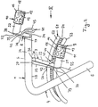
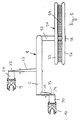
- the bicycle stand 1 shown in the drawings is suitable for parking two bikes 2 and 3 and can with a large number of identical stands in a row next to each other (Fig. 6) and also in rows one after the other (Fig. 7) to be ordered. It is therefore particularly suitable for covered parking, where relatively little and therefore expensive parking spaces are available. Such parking lots are mostly in public buildings like schools, Baths and the like, available where with these bike racks the space can be used optimally.
- the bike stand 1 has an L-shaped leg 4, which is preferably made from a tube. With the longer leg 5, the leg 4 is on the floor anchored while the other, somewhat shorter leg 6 runs horizontally and two holders 9 and 10 for the Bicycles 2 and 3 carries. The holders 9 and 10 are on Straps 7 and 8 attached across the leg 6th stand out and are directed opposite to each other.
- the holders 9 and 10 are in a manner known per se a clamping part 11, 12 provided with a (not shown) plug-in part in a cross from the carrier 7, 8th protruding pipe section 21, 22 is held.
- the clamping parts 11, 12 have opposing clamping legs 13, 14 or 15, 16, which have a clamping receptacle 17, 18 for a center or seat tube 19, 20 of the bicycles 2, 3 limit.
- the holders 9, 10 are on the supporting leg 4 arranged inclined that their clamping legs 13, 14; 15, 16 run perpendicular to the seat tube 19, 20. This allows the bicycles for parking directly in the direction of travel inserted into the clamping parts 11, 12 or again be removed.
- the center tubes 19, 20 of the bicycles 2, 3 as a result of elastic deformation of the clamping legs 13 to 16 clamping held.
- the Holders 9 and 10 on different sides of the horizontal leg 6 and at different heights as well as offset to each other.
- the holder 9 is attached to the carrier 7, the a support arm 23 with a stiffening strip 25 and has the pipe section 21.
- the support arm 23 is about half as long as the horizontal leg 6 of the supporting leg 4; its width corresponds approximately to the pipe diameter of the Mainstay.
- the ends 30 and 36 of the support arm 23 are rounded part-circle.
- the pipe section 21 is on the one end 30 preferably welded.
- On the top Edge 31 of the support arm 23 is the stiffening strip 25 on and extends perpendicular to the support arm 23. Die Stiffening strip 25 tapers from the leg leg 6 out.
- the free end 39 of the stiffening strip 25 extends close to the pipe section 21.
- the carrier 7 is substantially in the area below of the leg 6.
- the other carrier 8 has a support arm 24, which is about half is as long as the support arm, which is otherwise of the same design 23 and with one end on the front of the Leg leg 6 is attached. At the other end of the arm is attached to the pipe section 22 which is perpendicular to the Support arm 24 protrudes. At the opposite of the pipe section 22 Side of the support arm 24 is a stiffening strip 26 attached that towards her from the main leg 6 opposite end is continuously tapered. The Stiffening strip 26 is 33 with its wider end on the top 34 of the support leg 6 while its narrow end 35 up to the height of the pipe section 22 is sufficient, but from the free end 32 of the support arm 24 distance Has.
- the two support arms 23, 24 are each strip-shaped trained and arranged upright.
- the holders 9, 10 extend in the same direction and are parallel to each other (Fig. 4 and 5).
- the fuse parts preferably consist of rings, the a ring in an opening 42 or 43 of the support arm 23; 24 is attached.
- Fig. 6 shows, is advantageous on public Parking spaces where space is limited, one A large number of stands 1 arranged in a row next to one another, with the same distance from each other, which is slightly larger than the maximum width of the Handlebar 57.
- the distance is between the two bicycles 2 and 3 preferably 35 cm so that the distance between adjacent Bikes 2 and the second, supported on the support 51 Bicycles 3 is 70 cm, each measured between the bicycle's median longitudinal planes.
- Such Rows of bike racks can also be used in any Length and in any number with a distance behind each other be arranged as shown in FIG. 7. Even with one Such an arrangement makes parking the bicycles easy possible, with the largest possible in the smallest space Number of bicycles can be parked.
Landscapes
- Engineering & Computer Science (AREA)
- Mechanical Engineering (AREA)
- Steering Devices For Bicycles And Motorcycles (AREA)
- Fittings On The Vehicle Exterior For Carrying Loads, And Devices For Holding Or Mounting Articles (AREA)
- Axle Suspensions And Sidecars For Cycles (AREA)
- Automatic Cycles, And Cycles In General (AREA)
- Handcart (AREA)
Claims (17)
- Porte-bicyclettes (1) comprenant un pied (4) dirigé vers le haut, sur lequel sont prévus deux supports (7, 8) qui dépassent dans des directions opposées perpendiculairement depuis le pied (4), et qui comportent des éléments de maintien (9, 10) pour des bicyclettes (2, 3), lesquels dépassent perpendiculairement depuis les supports (7, 8),
caractérisé en ce que le pied (4) comprend un bras horizontal supérieur (6), depuis lequel dépassent perpendiculairement les supports (7, 8), et en ce que les deux éléments de maintien (9, 10) sont agencés de façon décalée l'un par rapport à l'autre dans la direction de la hauteur du pied (4) et inclinés vers le bas. - Porte-bicyclettes selon la revendication 1, caractérisé en ce que l'un des éléments de maintien (9) présente par rapport au bras horizontal (6) du pied (4) une distance plus élevée que l'autre élément de maintien (10).
- Porte-bicyclettes selon l'une ou l'autre des revendications 1 et 2, caractérisé en ce que les éléments de maintien (9, 10) sont prévus sur un bout de tube (21, 22) agencé en oblique vers le bas et fixé sur le support (7, 8).
- Porte-bicyclettes selon l'une des revendications 1 à 3, caractérisé en ce que les supports (7, 8) comprennent respectivement un bras de support (23, 24) en forme de plaque et pourvu d'au moins une partie de rigidification (25, 26).
- Porte-bicyclettes selon l'une des revendications 1 à 4, caractérisé en ce que l'un des supports (8) est prévu à l'extrémité libre du bras horizontal (6) du pied (4), et en ce que l'autre support (7) est prévu à distance de l'extrémité libre du bras horizontal (6).
- Porte-bicyclettes selon l'une des revendications 1 à 5, caractérisé en ce que les éléments de maintien (9, 10) comprennent des pièces de serrage (11, 12) dans lesquelles les bicyclettes (2, 3) sont maintenues de façon serrée par leur tube central ou leur tube de siège (19, 20).
- Porte-bicyclettes selon l'une des revendications 1 à 6, caractérisé en ce qu'il est prévu sur un bras vertical (5) du pied (4) un soutien (51) sur l'un des côtés du pied et à distance du sol (57).
- Porte-bicyclettes selon la revendication 7, caractérisé en ce que le soutien (51) est réalisé sous forme de rampe d'introduction pour une roue avant de la bicyclette (2, 3).
- Porte-bicyclettes selon l'une ou l'autre des revendications 7 et 8, caractérisé en ce que le soutien (51) est situé du même côté que l'élément de maintien (10) qui est prévu à la plus petite distance latérale du pied (4).
- Porte-bicyclettes selon l'une des revendications 7 à 9, caractérisé en ce que le soutien (51) est réalisé approximativement sous forme de demi-cercle.
- Porte-bicyclettes selon l'une des revendications 7 à 10, caractérisé en ce que le soutien (51) est agencé sur un bras (55) et présente vis-à-vis du pied (4) une distance supérieure à l'un des éléments de maintien (10).
- Porte-bicyclettes selon l'une des revendications 7 à 11, caractérisé en ce que le soutien (51) comprend deux arcs tubulaires (52, 53) latéraux situés à distance l'un de l'autre, lesquels sont reliés l'un à l'autre par l'intermédiaire d'une surface d'appui (54) pour la roue (55).
- Porte-bicyclettes selon la revendication 12, caractérisé en ce que la surface d'appui (54) est formée d'un matériau en grillage.
- Porte-bicyclettes selon l'une ou l'autre des revendications 12 et 13, caractérisé en ce que la distance des arcs tubulaires (52, 53) l'un de l'autre est supérieure à la largeur de la roue avant (55) de la bicyclette (2, 3).
- Porte-bicyclettes selon l'une des revendications 12 à 14, caractérisé en ce que le soutien (51) est appliqué par son arc tubulaire extérieur (52) contre une butée (56).
- Porte-bicyclettes selon l'une des revendications 4 à 15, caractérisé en ce qu'au moins une pièce de blocage (40, 41) est fixée sur les bras de support (23, 24) des supports (7, 8).
- Porte-bicyclettes selon la revendication 16, caractérisé en ce que la pièce de blocage (40, 41) est une bague de blocage.
Applications Claiming Priority (2)
| Application Number | Priority Date | Filing Date | Title |
|---|---|---|---|
| DE9416533U DE9416533U1 (de) | 1994-10-14 | 1994-10-14 | Fahrradständer |
| DE9416533U | 1994-10-14 |
Publications (2)
| Publication Number | Publication Date |
|---|---|
| EP0706932A1 EP0706932A1 (fr) | 1996-04-17 |
| EP0706932B1 true EP0706932B1 (fr) | 1998-11-25 |
Family
ID=6914872
Family Applications (1)
| Application Number | Title | Priority Date | Filing Date |
|---|---|---|---|
| EP95114093A Expired - Lifetime EP0706932B1 (fr) | 1994-10-14 | 1995-09-08 | Support de bicyclette |
Country Status (3)
| Country | Link |
|---|---|
| EP (1) | EP0706932B1 (fr) |
| AT (1) | ATE173691T1 (fr) |
| DE (2) | DE9416533U1 (fr) |
Families Citing this family (5)
| Publication number | Priority date | Publication date | Assignee | Title |
|---|---|---|---|---|
| DE29614368U1 (de) * | 1996-08-20 | 1996-10-02 | Eisen- Und Drahtwerk Erlau Ag, 73431 Aalen | Ständer für Fahrräder |
| DE29717209U1 (de) | 1997-09-26 | 1997-11-06 | Eisen- Und Drahtwerk Erlau Ag, 73431 Aalen | Fahrradständer |
| FR2774651B1 (fr) * | 1998-02-10 | 2000-03-10 | Claude Loirand | Dispositif destine au stationnement et a la protection antivol des cycles et velos |
| DE102010052793A1 (de) | 2010-06-14 | 2011-12-15 | Götz Siegmann | Fahrradständer mit Sicherung gegen Diebstahl |
| CA3041118A1 (fr) | 2016-10-19 | 2018-04-26 | Jeffrey Richard OLINGER | Systeme de support de velo a haute densite |
Family Cites Families (5)
| Publication number | Priority date | Publication date | Assignee | Title |
|---|---|---|---|---|
| US4371082A (en) * | 1980-11-03 | 1983-02-01 | Iowa State University Research Foundation, Inc. | Bicycle rack |
| FR2558430A1 (fr) * | 1984-01-20 | 1985-07-26 | Greffe Gerald | Support de stabilisation pour engins a deux roues non pourvus de bequilles |
| DE9011763U1 (de) * | 1990-08-13 | 1990-12-06 | Winter, Bruno, 2000 Hamburg | Fahrrad-Abstellanlage mit diebstahlsicherer Abschließmöglichkeit |
| CH684185A5 (de) * | 1991-06-07 | 1994-07-29 | Alteag Fabrikations Und Handel | Einrichtung zum Einstellen von Fahrrädern. |
| DE9311668U1 (de) * | 1993-07-31 | 1993-11-04 | Hock, Hans Joachim, 67269 Grünstadt | Sicherheitseinrichtung |
-
1994
- 1994-10-14 DE DE9416533U patent/DE9416533U1/de not_active Expired - Lifetime
-
1995
- 1995-09-08 AT AT95114093T patent/ATE173691T1/de not_active IP Right Cessation
- 1995-09-08 EP EP95114093A patent/EP0706932B1/fr not_active Expired - Lifetime
- 1995-09-08 DE DE59504322T patent/DE59504322D1/de not_active Expired - Lifetime
Also Published As
| Publication number | Publication date |
|---|---|
| ATE173691T1 (de) | 1998-12-15 |
| DE9416533U1 (de) | 1996-02-15 |
| DE59504322D1 (de) | 1999-01-07 |
| EP0706932A1 (fr) | 1996-04-17 |
Similar Documents
| Publication | Publication Date | Title |
|---|---|---|
| DE3928320C2 (fr) | ||
| DE1684219B2 (de) | Vorrichtung zum Verbinden von Gerüstteilen | |
| EP0706932B1 (fr) | Support de bicyclette | |
| DE102008013535A1 (de) | Fahrradparker | |
| DE3240479A1 (de) | Fahrradabstellanlage | |
| DE3901240C2 (de) | Aufstellvorrichtung für einen Mobilzaun | |
| CH668400A5 (en) | Stand for bicycle - has frame carrying guide tracks sloping up from frame with upper downward sloping section and holder for bicycle pedal crank arm | |
| DE4407062C2 (de) | Fahrradständermodul | |
| DE102012020644B4 (de) | Fahrradständer mit Schrägstellung | |
| EP0944517B1 (fr) | Support pour bicyclettes | |
| DE29505264U1 (de) | Fahrradständer | |
| EP0905012A2 (fr) | Support de bicyclette | |
| EP0668207B1 (fr) | Support de bicyclettes | |
| EP0468431B1 (fr) | Support de bicyclettes | |
| DE29606059U1 (de) | Ständer für Fahrräder | |
| EP0831018B1 (fr) | Support de bicyclette | |
| DE9308960U1 (de) | Zweiradständer, insbesondere für Fahrräder | |
| DE19948929C2 (de) | Fahrradparker | |
| EP0629544B1 (fr) | Support de stationnement pour véhicules à deux roues, en particulier pour bicyclettes | |
| DE202022106027U1 (de) | Fahrradabstellanlage und Bausatz zu deren Herstellung | |
| DE202006012354U1 (de) | Haltevorrichtung für Fahrräder | |
| CH683366A5 (de) | Vorrichtung zum Tragen eines Heizkessels. | |
| DE4438465A1 (de) | Trageeinrichtung für einen vorne an einem Fahrrad befindlichen Korb | |
| DE1459804C (de) | Schneezaun | |
| DE9401998U1 (de) | Säulenfahrradparker |
Legal Events
| Date | Code | Title | Description |
|---|---|---|---|
| PUAI | Public reference made under article 153(3) epc to a published international application that has entered the european phase |
Free format text: ORIGINAL CODE: 0009012 |
|
| AK | Designated contracting states |
Kind code of ref document: A1 Designated state(s): AT BE CH DE FR GB IT LI NL |
|
| 17P | Request for examination filed |
Effective date: 19960607 |
|
| 17Q | First examination report despatched |
Effective date: 19970929 |
|
| GRAG | Despatch of communication of intention to grant |
Free format text: ORIGINAL CODE: EPIDOS AGRA |
|
| GRAG | Despatch of communication of intention to grant |
Free format text: ORIGINAL CODE: EPIDOS AGRA |
|
| GRAH | Despatch of communication of intention to grant a patent |
Free format text: ORIGINAL CODE: EPIDOS IGRA |
|
| ITF | It: translation for a ep patent filed | ||
| GRAH | Despatch of communication of intention to grant a patent |
Free format text: ORIGINAL CODE: EPIDOS IGRA |
|
| GRAA | (expected) grant |
Free format text: ORIGINAL CODE: 0009210 |
|
| AK | Designated contracting states |
Kind code of ref document: B1 Designated state(s): AT BE CH DE FR GB IT LI NL |
|
| REF | Corresponds to: |
Ref document number: 173691 Country of ref document: AT Date of ref document: 19981215 Kind code of ref document: T |
|
| REG | Reference to a national code |
Ref country code: CH Ref legal event code: NV Representative=s name: PATENTANWALTSBUERO JEAN HUNZIKER Ref country code: CH Ref legal event code: EP |
|
| GBT | Gb: translation of ep patent filed (gb section 77(6)(a)/1977) |
Effective date: 19981201 |
|
| REF | Corresponds to: |
Ref document number: 59504322 Country of ref document: DE Date of ref document: 19990107 |
|
| ET | Fr: translation filed | ||
| PLBE | No opposition filed within time limit |
Free format text: ORIGINAL CODE: 0009261 |
|
| STAA | Information on the status of an ep patent application or granted ep patent |
Free format text: STATUS: NO OPPOSITION FILED WITHIN TIME LIMIT |
|
| 26N | No opposition filed | ||
| PGFP | Annual fee paid to national office [announced via postgrant information from national office to epo] |
Ref country code: FR Payment date: 20010817 Year of fee payment: 7 |
|
| PGFP | Annual fee paid to national office [announced via postgrant information from national office to epo] |
Ref country code: GB Payment date: 20010912 Year of fee payment: 7 |
|
| PGFP | Annual fee paid to national office [announced via postgrant information from national office to epo] |
Ref country code: CH Payment date: 20010914 Year of fee payment: 7 |
|
| PGFP | Annual fee paid to national office [announced via postgrant information from national office to epo] |
Ref country code: AT Payment date: 20010927 Year of fee payment: 7 |
|
| PGFP | Annual fee paid to national office [announced via postgrant information from national office to epo] |
Ref country code: BE Payment date: 20010928 Year of fee payment: 7 |
|
| REG | Reference to a national code |
Ref country code: GB Ref legal event code: IF02 |
|
| PG25 | Lapsed in a contracting state [announced via postgrant information from national office to epo] |
Ref country code: GB Free format text: LAPSE BECAUSE OF NON-PAYMENT OF DUE FEES Effective date: 20020908 Ref country code: AT Free format text: LAPSE BECAUSE OF NON-PAYMENT OF DUE FEES Effective date: 20020908 |
|
| PG25 | Lapsed in a contracting state [announced via postgrant information from national office to epo] |
Ref country code: LI Free format text: LAPSE BECAUSE OF NON-PAYMENT OF DUE FEES Effective date: 20020930 Ref country code: CH Free format text: LAPSE BECAUSE OF NON-PAYMENT OF DUE FEES Effective date: 20020930 Ref country code: BE Free format text: LAPSE BECAUSE OF NON-PAYMENT OF DUE FEES Effective date: 20020930 |
|
| BERE | Be: lapsed |
Owner name: *EISEN- UND DRAHTWERK ERLAU A.G. Effective date: 20020930 |
|
| GBPC | Gb: european patent ceased through non-payment of renewal fee |
Effective date: 20020908 |
|
| REG | Reference to a national code |
Ref country code: CH Ref legal event code: PL |
|
| PG25 | Lapsed in a contracting state [announced via postgrant information from national office to epo] |
Ref country code: FR Free format text: LAPSE BECAUSE OF NON-PAYMENT OF DUE FEES Effective date: 20030603 |
|
| REG | Reference to a national code |
Ref country code: FR Ref legal event code: ST |
|
| PG25 | Lapsed in a contracting state [announced via postgrant information from national office to epo] |
Ref country code: IT Free format text: LAPSE BECAUSE OF NON-PAYMENT OF DUE FEES;WARNING: LAPSES OF ITALIAN PATENTS WITH EFFECTIVE DATE BEFORE 2007 MAY HAVE OCCURRED AT ANY TIME BEFORE 2007. THE CORRECT EFFECTIVE DATE MAY BE DIFFERENT FROM THE ONE RECORDED. Effective date: 20050908 |
|
| PGFP | Annual fee paid to national office [announced via postgrant information from national office to epo] |
Ref country code: NL Payment date: 20080930 Year of fee payment: 14 |
|
| REG | Reference to a national code |
Ref country code: NL Ref legal event code: V1 Effective date: 20100401 |
|
| PGFP | Annual fee paid to national office [announced via postgrant information from national office to epo] |
Ref country code: DE Payment date: 20100114 Year of fee payment: 15 |
|
| PG25 | Lapsed in a contracting state [announced via postgrant information from national office to epo] |
Ref country code: NL Free format text: LAPSE BECAUSE OF NON-PAYMENT OF DUE FEES Effective date: 20100401 |
|
| REG | Reference to a national code |
Ref country code: DE Ref legal event code: R119 Ref document number: 59504322 Country of ref document: DE Effective date: 20110401 |
|
| PG25 | Lapsed in a contracting state [announced via postgrant information from national office to epo] |
Ref country code: DE Free format text: LAPSE BECAUSE OF NON-PAYMENT OF DUE FEES Effective date: 20110401 |