EP0706937B1 - Vorrichtung zur Verstellsteuerung der Blätter eines Hubschrauberrotors - Google Patents
Vorrichtung zur Verstellsteuerung der Blätter eines Hubschrauberrotors Download PDFInfo
- Publication number
- EP0706937B1 EP0706937B1 EP95402253A EP95402253A EP0706937B1 EP 0706937 B1 EP0706937 B1 EP 0706937B1 EP 95402253 A EP95402253 A EP 95402253A EP 95402253 A EP95402253 A EP 95402253A EP 0706937 B1 EP0706937 B1 EP 0706937B1
- Authority
- EP
- European Patent Office
- Prior art keywords
- pitch
- rotating plate
- lever
- articulation
- articulated
- Prior art date
- Legal status (The legal status is an assumption and is not a legal conclusion. Google has not performed a legal analysis and makes no representation as to the accuracy of the status listed.)
- Expired - Lifetime
Links
- 230000007246 mechanism Effects 0.000 claims description 9
- RZVHIXYEVGDQDX-UHFFFAOYSA-N 9,10-anthraquinone Chemical compound C1=CC=C2C(=O)C3=CC=CC=C3C(=O)C2=C1 RZVHIXYEVGDQDX-UHFFFAOYSA-N 0.000 claims description 3
- 230000009471 action Effects 0.000 claims description 3
- 230000000717 retained effect Effects 0.000 description 22
- 125000002619 bicyclic group Chemical group 0.000 description 13
- 125000002950 monocyclic group Chemical group 0.000 description 13
- 125000004122 cyclic group Chemical group 0.000 description 9
- 230000008901 benefit Effects 0.000 description 5
- 230000010363 phase shift Effects 0.000 description 5
- 238000006073 displacement reaction Methods 0.000 description 3
- 230000008859 change Effects 0.000 description 2
- 230000006835 compression Effects 0.000 description 2
- 238000007906 compression Methods 0.000 description 2
- 230000035939 shock Effects 0.000 description 2
- 241000283899 Gazella Species 0.000 description 1
- 241000940835 Pales Species 0.000 description 1
- 206010033546 Pallor Diseases 0.000 description 1
- 241001080024 Telles Species 0.000 description 1
- 230000003416 augmentation Effects 0.000 description 1
- 238000010276 construction Methods 0.000 description 1
- 230000008878 coupling Effects 0.000 description 1
- 238000010168 coupling process Methods 0.000 description 1
- 238000005859 coupling reaction Methods 0.000 description 1
- 230000007423 decrease Effects 0.000 description 1
- 230000000694 effects Effects 0.000 description 1
- 230000005284 excitation Effects 0.000 description 1
- 230000009931 harmful effect Effects 0.000 description 1
- 230000006872 improvement Effects 0.000 description 1
- 230000010355 oscillation Effects 0.000 description 1
- 238000005086 pumping Methods 0.000 description 1
- 230000009467 reduction Effects 0.000 description 1
Images

Classifications
-
- B—PERFORMING OPERATIONS; TRANSPORTING
- B64—AIRCRAFT; AVIATION; COSMONAUTICS
- B64C—AEROPLANES; HELICOPTERS
- B64C27/00—Rotorcraft; Rotors peculiar thereto
- B64C27/54—Mechanisms for controlling blade adjustment or movement relative to rotor head, e.g. lag-lead movement
- B64C27/58—Transmitting means, e.g. interrelated with initiating means or means acting on blades
- B64C27/59—Transmitting means, e.g. interrelated with initiating means or means acting on blades mechanical
- B64C27/605—Transmitting means, e.g. interrelated with initiating means or means acting on blades mechanical including swash plate, spider or cam mechanisms
Definitions
- the invention relates to a device for controlling not blades of a rotorcraft rotor, of the plate type cyclic, on which each blade is, on the one hand, driven rotating around an axis of rotation of a rotor mast by through a hub, integral with the rotor mast, and, on the other hand, integral in rotation, around an axis longitudinal blade pitch change, lever not articulated with a pitch rod connected to a plate rotating with the rotor mast and belonging to a mechanism with swashplates, in which the turntable is rotatably mounted on a non-rotating plate that can slide axially along the rotor mast and tilt in any direction relative to the rotor mast, under the action flight control actuators.
- the pitch control device of the invention is in particular intended to equip a main rotor with a very high speed helicopter, especially in translation forward.
- the pitch pitch control devices of a helicopter rotor comprising a conventional mechanism with swashplates allow to produce, as a benchmark turning with the rotor mast and the hub, on the one hand, one step collective simultaneously given to all the blades, and, on the other hand, a cyclical step, adding to the collective step and applied to each blade at the frequency of rotation.
- a helicopter in translation at very high speed is particularly faced with these limitations, due to the significant asymmetry of the speeds between its blade (s) advancing, at a Mach number between 0.5 and 0.9, and his receding blade (s), Mach number between 0 and 0.3.
- An object of the invention is to propose a device control module capable of applying a step component bicyclic, which is independent of the general or collective step, in order to obtain a weak pitch on the blade (s) forward as well as a moderate step on the blade (s) which are possibly of a phase shift determined with respect to conventional monocyclic control.
- another object of the invention is to propose a pitch control device such as this bicyclic control also helps reduce excitement, frequency 2 ⁇ , components of longitudinal shear forces and lateral of the dynamic torsor of the head of a rotor three-bladed.
- a pitch control device such as this bicyclic control also helps reduce excitement, frequency 2 ⁇ , components of longitudinal shear forces and lateral of the dynamic torsor of the head of a rotor three-bladed.
- a bicyclic step control can advantageously affect the so-called “pumping” component, that is to say along the axis rotor, of the dynamic torsor of a two-bladed rotor, as well as on the mode of deformation "in scissors” of a quadrupal rotor.
- the bicyclic step control does not allow to influence favorably on the dynamic torsor of the rotor head.
- the advantage of the invention then lies in the increase performance in terms of power consumed by the rotor, to reach a given flight speed.
- the pitch control device of the type presented above is characterized, according to the invention, in that it includes a secondary turntable, integral in rotation with the rotor mast and in axial translation of the non-rotating table, but not tilting relative to the rotor mast, and, for each blade, an articulated link to two levers and four joints, such as its two levers are articulated one on the other by a first articulation, that a first lever is also articulated by a second articulation on a fixed point in reference rotating with the secondary turntable, and that the second lever is also articulated on the pitch rod corresponding by a third articulation, distinct from the articulation of the pitch rod on the pitch lever, and the second lever is also articulated on a fixed point in turning mark with the turntable by the fourth joint, distinct from other joints, so that the inclinations of the swashplates by the actuators induce angular maneuvers of the levers each articulated link controlling the pitch of the blade corresponding by the operation of the corresponding pitch rod.
- the first articulation connects the two levers by one of their ends, the other end of the first lever being connected to a point fixed of the secondary turntable by the second articulation, while another end of the second lever is connected by the third joint to one end of the corresponding pitch rod, articulated by its other end on one end of the pitch lever, the fourth articulation connecting the second lever to the end of a arm secured to the turntable.
- the non-rotating plate is mounted tiltable around a ball joint itself sliding axially around a fixed tubular guide surrounding the rotor mast
- the plate secondary turning point of the device of the invention either secured to the ball in axial translation.
- this is obtained by mounting the secondary rotary turntable at using at least one bearing on a tubular guide secondary, integral with the ball joint in axial translation around the fixed tubular guide.
- the rotary drive of the turntable secondary can be insured, as is known for the rotary drive of the turntable, by at least a rotating compass, articulated on the one hand on the plate secondary turning and secondly on the rotor mast. But, according to the invention, this rotational drive can also, in a simple way, be insured by at least one finger, fixed to the rotor mast projecting laterally on this last, and connected to the secondary turntable by a axially sliding connection.
- the rotational drive of the plate turning can be ensured by at least one rotating compass, articulated on the turntable and on the rotor mast, classic way, or, according to specific realizations the invention, by the secondary turntable, by at least one rotating compass articulated on the turntable and on the secondary turntable by at least one pivoting connection around an axis substantially perpendicular to the rotor axis, or via at least one articulated link, acting as a compass rotating, to reduce the size and weight of the device.
- the first articulation consists of a pivoting link comprising a clevis of the first or second lever in which a socket of the second or first respectively lever is pivotally mounted around an axis substantially perpendicular to the rotor axis
- the second joint is consisting of a pivoting connection comprising a yoke of the secondary turntable or first lever in which a socket respectively of the first lever or of the secondary turntable is pivotally mounted around a axis substantially perpendicular to the rotor axis
- the third articulation consists of a ball joint mounted in the second lever or the pitch rod and retained in a yoke respectively of the pitch rod or the second lever
- the fourth joint consists of a ball joint mounted in the second lever or an arm of the turntable and retained in a yoke respectively said arm of the turntable or the second lever.
- the second lever consists of a triangular arm whose two vertices at the ends of a first side are connected by the first and third joints first lever and pitch rod respectively corresponding, and whose third vertex of the triangular arm is connected by the fourth joint to an arm corresponding to the turntable.
- the secondary turntable has a yoke in which is retained a ball joint of a end of the corresponding first lever, the other of which end is arranged in a screed in which is retained a ball joint from one of the vertices to the ends from the first side of the triangular arm, the vertex to the other end of the first side of said triangular arm being fitted out as a yoke in which the corresponding pitch rod is articulated by a pivot, the third vertex of the triangular arm being articulated by a ball joint in a yoke provided at the end of the corresponding arm of the tray turning, which makes it possible to obtain a particularly architecture picked up around the rotor mast.
- the second lever may consist of a bent arm, the ends of which are connected to the first lever and corresponding pitch rod respectively by the first and third joints, and whose bent central part is connected to a corresponding arm of the turntable by the fourth articulation.
- the first and third joints can be ball joints
- the fourth joint is a pivoting connection around a axis substantially perpendicular to the radial plane passing through the rotor axis and through the center of the pivoting link.
- the center of the ball joint constituting the third joint is offset laterally from the radial plane passing through the rotor axis and through the center of the link pivoting constituting the fourth articulation, the amplitude lateral offset being an increasing function of the phase shift searched between the bicyclic control and the monocyclic control.
- the secondary turntable has a yoke in which is retained, to form the second articulation, a ball joint mounted in one end of the first lever, the other end of which is also equipped with a ball joint retained, to form the first articulation, in a yoke at one end of the bent arm, the part of which bent central unit includes a pivotally retained socket, to form the fourth joint, around an axis in a yoke provided at the end of the corresponding arm of the turntable, the other end of the bent arm having an offset yoke parallel to the pivot axis of the socket, and in which is retained, to form the third joint, a ball joint mounted in the end corresponding to the corresponding pitch rod.
- the rotational drive of the plate turning by the secondary turntable is advantageously provided by at least one conventional rotating compass.
- the device according to the invention for controlling the not rotor blades, thus has the advantage of offering power gains, especially in the vicinity of the stall of the rotor, and delay the stall of the blade (s) receding.
- the system thus intervenes in the dropout of each receding blade, the harmful effects of which it reduces by reducing its local incidence.
- the device pushes back the limits linked to the dropout phenomenon blades, such as control forces, level vibration in the cabin and the dynamic moments along the blades.
- the device according to the invention also has the additional advantage of being easily adaptable, in catch-up, on existing helicopters.
- the pitch control device has axial and radial dimensions particularly reduced, and forms a compact unit with the mechanism with swashplates which it incorporates.
- a main rotor 1 of a helicopter shown schematically, includes a rotor mast 2 driven by its base rotating around the axis of rotation A-A of the rotor, and secured at its upper end to a hub 3.
- Each of the blades such as 4 of the rotor is connected to the hub 3 so as to be rotated with the latter around the rotor axis A-A, and so that it can pivot relative to the hub 3 around its longitudinal axis of pitch change X-X, substantially radial with respect to axis A-A.
- the blade 4 is integral in rotation around this axis X-X with a lever step 5.
- the lever 5 is articulated by its end on the upper end of a pitch rod 6, extending substantially in the direction of the rotor axis A-A, and connected by its lower end to the turntable 8 of a swashplate mechanism 7.
- the turntable 8 can be rotated by the mast rotor 2 using at least one rotating compass (not shown) articulated by one end on mast 2 and by the other end on the turntable 8.
- the latter is additionally mounted in rotation, using a ball bearing 9, coaxially on a non-rotating plate 10, which can tilt in any direction relative to the axis A-A around the mast 2 while being mounted by its hub 10a around a central ball 11, which can be translated parallel to the rotor axis A-A by the axial sliding of the ball 11 around a non-rotating cylindrical tubular guide 12, because fixed at fixed points in the structure of the helicopter, and surrounding the rotor mast 2.
- the non-rotating plate 10 is retained against any rotation around the axis rotor A-A by a non-rotating compass 13, partially shown, articulated by one end on the non-rotating plate 10 and by the other at a fixed point of the structure from the helicopter.
- the oscillation and translation of the non-rotating plate 10 are controlled by flight control actuators, generally numbering three, and only one of which 14 is shown in FIG. 1, and which may be connecting rods, jacks or servos.
- an articulated link 16 comprising two levers 17 and 18 and four joints 19, 20, 21 and 22, is mounted between the turntable 8, the pitch rod 6, and a secondary turntable 23, which is integral, with a part, in rotation of the rotor mast 2, on the other hand, in translation axial (along the rotor axis A-A) of the non-rotating plate 10, but which is blocked in inclination relative to the mast rotor 2.
- the secondary turntable 23 is integral in axial translation of the non-rotating plate 10 while being integral in axial translation with the ball joint 11. This is ensured by the rotary mounting of the secondary turntable 23 using a ball bearing 24 around the part upper of a secondary tubular guide 25, rendered secured to the ball 11 in axial translation around the fixed tubular guide 12.
- the secondary turntable 23 can be driven in rotation by the rotor mast 2, like the turntable 8, in a known manner using an articulated rotating compass by one end on the rotor mast 2 and by the other end on the secondary turntable 23. But, as shown in Figure 1, the rotational drive of secondary turntable 23 can be secured by a finger 26 square, fixed to the mast 2 projecting laterally on this last, and whose part parallel to mast 2 and its axis A-A axially crosses the plate 23 by a link axially sliding 27.
- the lower end of the first lever 17 of the link 16 is connected, by the first articulation 19 of this link 16, at the top at the lower end of a first side 28 of the second lever 18, in the form of an arm triangular, of this connection 16.
- the first arm 17 is connected by the second articulation 20 of the link 16 at a fixed point at the periphery of the secondary turntable 23.
- the second lever 18 is connected by the third articulation 21 of the link 16 at the lower end of the pitch rod 6 corresponding, articulated at 15 by its upper end on step lever 5.
- the arm triangular 18 is connected by the fourth articulation 22 of the link 16 at the end of a corresponding arm 29, secured to the turntable 8.
- each arm 29, integral with the plate turning 8 in its rotational movements on the platter non-rotating 10 and translating and tilting with this non-rotating plate 10 along and around the mast 2, can angularly operate the levers 17 and 18 of the link 16 corresponding to actuate the corresponding pitch rod 6, so as to obtain an optimized pitch control of the corresponding blade 4.
- the first side 28 of the arm 18 is the largest side of this triangular arm 18, and corresponds schematically to the longitudinal axis of the lever arm of reference 18, the ends of which are, on the one hand, the first articulation 19 connecting it to the other lever 17, and, on the other share, the third articulation 21 connecting it to the connecting rod not 6.
- the cyclic step is zero, because the joints 22, corresponding to the action points of the turntable 8 on all the articulated links 16, are in the same plane radial, perpendicular to the axis A-A of rotation of the rotor and passing through the center of the ball joint 11, so that for any azimuth position of a joint 22, around the rotor axis A-A, during a rotation of the turntable 8, the corresponding articulated link 16 retains the same position relative to its articulation 20 on the plate secondary turn 23, and the joint 15 of the end upper of the corresponding pitch rod 6 on the step lever 5 also keeps the same position when this rotation, which means that the cyclic step of the corresponding blade 4, therefore also of all the blades, is no.
- the position of the device is different from that of Figure 1 because the non-rotating plate 10 has been tilted by the actuators 14 around the ball joint 11 in a direction which has pivoted the left part from the non-rotating plate 10, visible in FIG. 2, towards the high on the figure, and therefore the right part (not shown) down.
- This inclination of the non-rotating table 10, and therefore also of the turntable 8 has for consequence that during a rotation around the rotor axis A-A, when an articulated link 16 is moved on the left of the axis A-A, its articulation 22 on the arm 29 of the turntable 8 is located above the radial plane perpendicular to the axis A-A and passing through the center of the ball joint 11, while when this articulated link 16 is moved to the right of the axis A-A, its articulation 22 is below this radial plane passing through the center of the ball joint 11.
- each articulation 22 occupies different successive positions, which control, by pressing the corresponding articulated link 16 on its articulation 20 on the turntable secondary 23, the alternating tilting of the triangular arm 18 around the joint 22, so as to exert alternately compression and tensile forces on the connecting rod of step 6 and thus to control by the articulation 15 the angular deflections of the step lever 5 and therefore the variation of the pitch of the corresponding blade.
- the position of the joint 22 above the plane radial passing through the center of the ball 11 causes the tilting of the triangular arm 18, with respect to its position of figure 1, which aligns the three joints 19, 21 and 15 on the same axis defined by the long side 28 of the triangular arm 18 and the pitch rod 6 in the extension from each other, which corresponds to compression applied to the connecting rod 6 thus displaced upwards rotating the pitch lever 5 and therefore the blade 4 corresponding around the corresponding X-X pitch axis.
- the device of the invention adapts to a swashplate mechanism 7 for controlling the pitch of blades of a helicopter rotor which allows to produce in landmark turning a collective or general step (by translation axial of the non-rotating 10 and rotating 8) plates and one pitch monocyclic (by tilting plates 10 and 8), this step monocyclic being the cyclic step at the frequency of ⁇ rotation of the rotor.
- the adoption of the device of the invention offers a more complex cyclic command by superimposing a bicyclic component on the component classic monocyclic, thanks to a mechanical arrangement suitable allowing, after a correct adjustment of the phases of the monocyclic and bicyclic components, to improve the operation of the rotor.
- the device of the invention also improves the vibrational behavior of a rotor at maximum speeds of current helicopters, from so the dynamic excitation torsor in particular three-bladed rotors can be significantly reduced.
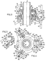
- FIG. 1 An example of the schematic device Figures 1 and 2 for a three-bladed helicopter is shown in Figures 3 to 5, but obviously the device of the invention can be applied to any other type of rotor, regardless of the number of blades.
- a secondary turntable 23 ' rotatably mounted by a bearing 24' around the guide secondary tubular 25 ', and therefore integral in axial translation of the ball 11 'and therefore of the plates non-rotating 10 'and rotating 8', but locked in inclination relative to the 2 'rotor mast, this secondary turntable 23 'being connected to each of the three rotor blades by one respectively of three articulated links with two levers and four joints each, which is articulated in the yoke 30 of an arm 29 'corresponding to the turntable 8' and also on the lower end of a connecting rod corresponding 6 'step, itself connected to a step lever to control the pitch of the corresponding blade.
- the secondary turntable 23 ' is driven in rotation by a rotating compass 31 articulated by its end upper in an external radial yoke 32 of the mast 2 ' and by its lower end, arranged in a socket or sleeve 31a, pivoting in a large radial yoke external 33 of the secondary turntable 23 ', around a bolted axis 34 substantially perpendicular to the radial plane passing through the axis A-A and through the middle of the yoke 33.
- the turntable 8 ' can be driven in rotation by the secondary turntable 23 ', according to a variant not shown of the invention, at by means of a rotating compass, the structure of which is similar to that of the rotating compass 31 for driving the plate secondary turn 23 'by the rotor mast 2'.
- the secondary turntable 23 rotates the 8 'turntable via a link articulated 16'a, shown on the right of Figures 3 and 4, and whose structure is different from that of the two other articulated links 16'b, above and below on the left of figure 4 and on figure 5.
- the secondary rotating plate 23 ' has a large outer radial yoke 35a, diametrically opposite to the clevis 33 of the articulation of the rotating compass 31.
- this yoke 35a the upper end arranged in a socket or sleeve 36a of a first lever 17'a of the link 16'a is retained around a bolted pivot transverse axis 37a according to a pivoting connection constituting the third joint 20'a of the link 16'a, connecting the latter to the secondary turntable 23 ', while the end lower lever 17'a is arranged in yoke 38a, in which is also retained by a pivoting link, around a bolted transverse pivot axis 39a, the sleeve or sleeve 40a formed at one end of the large side 28'a of the second lever 18'a of triangular shape of the link 16'a, to form the first articulation 19'a of this link 16
- the other end of the long side 28'a of the lever triangular 18'a is arranged in yoke 41a in which is retained around a transverse axis a ball joint 42a mounted in a ball joint constituting the end bottom of the 6 'pitch rod, to form the third articulation 21'a of this link 16'a, connecting its second lever 18'a at the pitch rod 6 '.
- the secondary turntable 23 ' has a small external radial yoke 35b in which is retained by a transverse axis a ball joint 36b mounted in the end upper of the first lever 17'b to constitute the second articulation 20'b of this link 16'b, connecting it to 23 'secondary turntable.
- the lower end of the lever 17'b is arranged in yoke 38b in which is retained by a transverse axis a ball joint 40b mounted in the lower end of the large side 28'b of the second lever 18'b in the shape of a triangular arm of this link 16'b, to form the first articulation 19'b articulating one on the other the two levers 17'b and 18'b of this link 16'b.
- the other end of the long side 28'b of the triangular arm 18'b is arranged in yoke 41b in which a small socket 42b at the lower end of the corresponding 6 'pitch rod is retained around a transverse axis by a pivoting link.
- each link 16'b is articulated to the corresponding arm 29 'of the plate turning 8 'by a ball joint 43b mounted in the third top of the triangular arm 18'b and retained by an axis transverse in the yoke 30 of the corresponding arm 29 'for constitute the fourth articulation 22'b of this link 16'b.
- each of the arms 29' can angularly operate the triangular arm 18'a or 18'b of the corresponding articulated link 16'a or 16'b, for activate the pitch rod 6 'and thus control the pitch of the corresponding blade as described above in reference to figure 2.
- the diametrically opposite arrangement of large yokes 33 and 35a on the secondary turntable 23 'with the large yoke 33 in the middle of the small yokes 35b, provides good balance of the three-bladed rotor. But it is good heard possible that, on such a three-bladed rotor, the large clevis 33 is diametrically opposite one of the two small yokes 35b of the secondary turntable 35b, and at middle between the other small screed 35b and the big screed 35a.
- the large yoke 33 hinge of the rotating compass 31 on the turntable secondary 23 ' can occupy one of the four positions possible, in the middle between two yokes 35a and / or 35b neighbors on the secondary plate 23 'for its connection to two of the articulated links 16 ', and it will be the same on a rotor with five, six, seven or more blades.
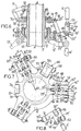
- Figures 6 to 8 show a variant of the device which is essentially different from that of Figures 3 to 5 as by the structure of each of the three 16 '' articulated connections, identical to each other in this variant, and by the structure of the 8 '' turntables and 23 '' secondary turn.
- the elements identical to those of FIGS. 3 to 5 are identified by the same reference numbers.
- the turntable 8 '' is rotatably mounted by the bearing 9 'around the hub 10'a of the non-rotating plate 10 ', held in rotation by the non-rotating compass 13 'and operated by the actuators 14' in inclination with respect to the rotor axis A-A and to the mast 2 ' by its hub 10'a around the ball 11 ', and in translation axial with ball joint 11 'and tubular guide secondary 25 ', as well as with the secondary turntable 23 '' and the bearing 24 'allowing its rotation on the guide 25 ', around the fixed tubular guide 12' surrounding the mast rotor 2 '.
- the secondary turntable 23 '' has a small external radial yoke 44, in which a bolted axis transverse 45 retains, to form the second articulation 20 '' from this 16 '' link, a ball joint 46 mounted in the end upper of the first straight lever 17 '' of the 16 '' link.
- the lower end of the 17 '' lever is also equipped with a ball joint 47 retained by an axis transversely bolted 48 in a yoke 49 at the end a substantially radial part of the second 18 '' lever this 16 '' link, this 18 '' lever being shaped as an arm angled, of which another part, substantially vertical, has its end also arranged in yoke 50.
- the angled central part of the 18 '' lever includes a socket 51, which is pivotally retained around an axis transverse bolted 52 in a large radial 30 '' clevis external to the end of a 29 '' radial arm of the plate turning 8 '', to make the fourth articulation 22 '' of the 16 '' connection, in the form of a pivoting connection around of a geometric axis substantially perpendicular to the plane radial passing through the rotor axis A-A and through the center of the 30 '' yoke and socket 51, corresponding to the center of this pivoting link.
- This radial plane also passes substantially by the centers of ball joints 46 and 47 and clevis 44 and 49, as well as by the median plane of the 17 '' lever.
- an essential feature of this variant is that the yoke 50 of the substantially vertical part of the 18 '' angled arm is laterally offset, parallel to the axis of the pivoting connection of the sleeve 51, with respect to in the radial plane passing through the center of this connection swivel.
- a ball joint 53 mounted at the lower end of the 6 'pitch rod, is retained by a transverse bolted axis 54 in clevis 50, to constitute the third 21 '' joint of the 16 '' link, through which the arm angled 18 '' of the latter is articulated to the pitch rod 6 '.
- the center of the 21 '' ball joint 53 is offset laterally from the passing radial plane by the rotor axis A-A and by the center of the pivoting link constituting the fourth articulation 22 '', that is to say substantially through the center of the socket 51 and the centers 19 '' and 20 '' ball joints 47 and 46 respectively.
- This lateral offset d is obtained in this variant by making the substantially vertical part 18 '' H-shaped bent arm (see Figure 8) attached laterally to the socket 51 of the bent central part of the 18 '' arm by one of the two parallel branches of the H which are on the opposite side to the yoke 50 formed by the other two parallel branches of the H, while the other branch 55 towards the central part forms, with the socket 51, another clevis in which is retained by the axis 52 one of the two 30 '' yoke arms of the 29 '' hollow arm corresponding to the 8 '' turntable.
- the latter is rotated by the secondary 23 '' turntable using a compass turning 56, the upper branch 56a of which is articulated by pivoting connections around parallel axes, one to the other and perpendicular to the rotor axis A-A, on the one hand, by its upper end in a large radial yoke external 57 of the secondary turntable 23 '', and, on the other part, by its lower end in a large yoke 58 from the upper end of the lower arm of the compass 56, which lower branch is articulated at its end lower by a ball joint in a small yoke external radial of the 8 '' turntable, not shown in Figures 6 to 8.
- the offset lateral d from the center of the third joint 21 '' from the articulated link 16 '' from the radial plane passing through the centers of the other joints of this 16 '' link, and in particular of the fourth articulation 22 '' corresponds to a phase shift between the conventional monocyclic control, linked to the 10 'and 8' 'swashplates, and the control bicyclic introduced by the 16 '' articulated links of the device of the invention, this phase shift being a function increasing lateral offset d.
- phase difference between these two commands can be expressed by the angle at the center ⁇ between the radial planes passing through the rotor axis A-A and one through the center of the 21 '' joint, and the other by the center of the 22 '' joint.
- the bicyclic control is therefore out of phase with the monocycl
Landscapes
- Engineering & Computer Science (AREA)
- Mechanical Engineering (AREA)
- Aviation & Aerospace Engineering (AREA)
- Transmission Devices (AREA)
- Toys (AREA)
Claims (14)
- Vorrichtung zur Steuerung des Anstellwinkels der Blätter eines Drehflügler-Rotors (1), insbesondere eines Hubschrauber-Hauptrotors, wobei jedes Blatt (4) einerseits um eine Drehachse (A-A) eines Rotormasts (2, 2') mittels einer Nabe (3) und andererseits drehvereint um eine Längsachse (X-X) zur Anstellwinkeländerung von einem Anstellwinkelhebel (5) drehangetrieben wird, der an eine Anstellwinkelstange (6, 6') angelenkt ist, die über eine Drehplatte (8, 8', 8'') mit dem Rotormast (2, 2') verbunden ist und zu einem Mechanismus (7) mit zyklischen Platten gehört, bei dem die Drehplatte (8, 8', 8'') auf einer nichtdrehenden Platte (10, 10') drehbar angebracht ist, die sich unter der Einwirkung von Betätigungsgliedern (14, 14') von Flugbefehlen axial entlang dem Rotormast (2, 2') verschieben und in jeder Richtung in bezug auf den Rotormast neigen läßt, dadurch gekennzeichnet, daß sie eine mit dem Rotormast (2, 2') drehvereinte und mit der nichtdrehenden Platte (10, 10') in der axialen Translationsbewegung vereinte, aber in bezug auf den Rotormast (2, 2') nicht neigbare Nebendrehplatte (23, 23', 23'') und für jedes Blatt eine gelenkige Verbindung (16, 16'a-b, 16'') mit zwei Hebeln (17-18; 17'a-b-18'a-b, 17''-18'') und vier Gelenken aufweist, die so beschaffen ist, daß ihre beiden Hebel miteinander durch ein erstes Gelenk (19, 19'a-b, 19'') gelenkig verbunden sind, daß ein erster Hebel (17, 17'a-b, 17'') überdies durch ein zweites Gelenk (20, 20'a-b, 20'') mit einem festen, sich mit der Nebendrehplatte (23, 23', 23'') drehenden Bezugspunkt gelenkig verbunden ist und daß der zweite Hebel (18, 18'a-b, 18'') überdies mit der entsprechenden Anstellwinkelstange (6, 6') durch ein drittes, gegenüber dem die Anstellwinkelstange (6, 6') mit dem Anstellwinkelhebel (5) verbindenden Gelenk (15) verschiedenes Gelenk (21, 21'a-b, 21'') gelenkig verbunden ist und der zweite Hebel (18, 18'a-b, 18'') darüber hinaus mit einem festen, sich mit der Drehplatte (8, 8', 8'') drehenden Bezugspunkt (29, 29', 29'') durch das vierte, gegenüber den anderen Gelenken verschiedene Gelenk (22, 22'a-b, 22'') gelenkig verbunden ist, so daß die Neigungen der zyklischen Platten durch die Betätigungsglieder (14, 14') Winkelbetätigungen der Hebel (17, 18; 17'a-b, 18'a-b; 17'', 18'') jeder gelenkigen Verbindung (16, 16'a-b, 16'') bewirken, die den Anstellwinkel des entsprechenden Blattes (4) durch die Betätigung der entsprechenden Anstellwinkelstange (6, 6') steuert.
- Vorrichtung zur Steuerung des Anstellwinkels nach Anspruch 1, dadurch gekennzeichnet, daß für jede gelenkige Verbindung (16, 16'a-b, 16'') das erste Gelenk (19, 19'a-b, 19'') die beiden Hebel (17, 17'a-b, 17'', 18, 18'a-b, 18'') durch eines ihrer Enden verbindet, wobei das andere Ende des ersten Hebels (17, 17'a-b, 17'') mit einem festen Punkt der Nebendrehplatte (23, 23', 23'') durch das zweite Gelenk (20, 20'a-b, 20'') verbunden ist, während ein anderes Ende des zweiten Hebels (18, 18'a-b, 18'') durch das dritte Gelenk (21, 21'a-b, 21'') mit einem Ende der entsprechenden Anstellwinkelstange (6, 6') verbunden ist, die durch ihr anderes Ende mit einem Ende des Anstellwinkelhebels (5) gelenkig (15) verbunden ist, wobei das vierte Gelenk (22, 22'a-b, 22'') den zweiten Hebel (18, 18'a-b, 18'') mit dem Ende eines mit der Drehplatte (8, 8', 8'') vereinten Armes (29, 29', 29'') verbindet.
- Vorrichtung zur Steuerung des Anstellwinkels nach einem der Ansprüche 1 und 2, bei der die nichtdrehende Platte (10, 10') um einen Kugelkopf (11, 11') neigbar angebracht ist, der selbst axial verschiebbar um eine den Rotormast (2, 2') umfassende feste rohrförmige Führung (12, 12') herum angebracht ist, dadurch gekennzeichnet, daß die Nebendrehplatte (23, 23', 23'') mit dem Kugelkopf (11, 11') in der axialen Translationsbewegung vereint ist.
- Vorrichtung zur Steuerung des Anstellwinkels nach Anspruch 3, dadurch gekennzeichnet, daß die Nebendrehplatte (23, 23', 23'') mit Hilfe wenigstens eines Wälzlagers (24, 24') auf einer rohrförmigen Nebenführung (25, 25') drehbar angebracht ist, die mit dem Kugelkopf (11, 11') bei axialer Translationsbewegung um die feste rohrförmige Führung (12, 12') vereint ist.
- Vorrichtung zur Steuerung des Anstellwinkels nach einem der Ansprüche 1 bis 4, dadurch gekennzeichnet, daß die Nebendrehplatte (23, 23') durch mindestens einen Drehzirkel (31) drehangetrieben ist, der einerseits an der Nebendrehplatte (23, 23') und andererseits am Rotormast (2') angelenkt ist.
- Vorrichtung zur Steuerung des Anstellwinkels nach einem der Ansprüche 1 bis 4, dadurch gekennzeichnet, daß die Nebendrehplatte (23) durch mindestens einen Finger (26) drehangetrieben ist, der am Rotormast (2) seitlich abstehend von diesem befestigt und mit der Nebendrehplatte (23) durch eine axial verschiebbare Verbindung (27) verbunden ist.
- Vorrichtung zur Steuerung des Anstellwinkels nach einem der Ansprüche 1 bis 6, dadurch gekennzeichnet, daß die Nebendrehplatte (23'') die Drehplatte (8'') durch mindestens einen Drehzirkel (56) drehantreibt, der an der Drehplatte (8'') und an der Nebendrehplatte (23'') durch mindestens eine um eine zur Rotorachse (A-A) im wesentlichen senkrechte Achse schwenkende Verbindung (57) angelenkt ist.
- Vorrichtung zur Steuerung des Anstellwinkels nach einem der Ansprüche 1 bis 6, dadurch gekennzeichnet, daß die Nebendrehplatte (23') die Drehplatte (8') durch mindestens eine gelenkige Verbindung (16'a) drehantreibt, die eine Drehzirkelfunktion ausübt.
- Vorrichtung zur Steuerung des Anstellwinkels nach Anspruch 8, dadurch gekennzeichnet, daß für die die Drehzirkelfunktion ausübende gelenkige Verbindung (16'a) das erste Gelenk (19'a) aus einer Schwenkverbindung besteht, die einen Gabelkopf (38a) des ersten (17'a) oder des zweiten Hebels (18'a) enthält, in dem eine Buchse (40a) des zweiten (18'a) bzw. des ersten Hebels (17'a) schwenkbar um eine zur Rotorachse (A-A) im wesentlichen senkrechte Achse (39a) angebracht ist, das zweite Gelenk (20'a) aus einer Schwenkverbindung gebildet ist, die einen Gabelkopf (35a) der Nebendrehplatte (23') oder des ersten Hebels (17'a) enthält, in dem eine Buchse (36a) des ersten Hebels (17'a) bzw. der Nebendrehplatte (23') schwenkbar um eine zur Rotorachse (A-A) im wesentlichen senkrechte Achse (37a) angebracht ist, das dritte Gelenk (21'a) aus einer Kugelkopfverbindung (42a) gebildet ist, die im zweiten Hebel (18'a) oder der Anstellwinkelstange (6') angebracht und in einem Gabelkopf (41a) der Anstellwinkelstange (6') bzw. des zweiten Hebels (18'a) gehalten ist, und das vierte Gelenk (22'a) aus einer Kugelkopfverbindung (43a) gebildet ist, die im zweiten Hebel (18'a) oder einem Arm (29') der Drehplatte (8') angebracht und in einem Gabelkopf (30) dieses Armes (29') der Drehplatte (8') bzw. des zweiten Hebels (18'a) gehalten ist.
- Vorrichtung zur Steuerung des Anstellwinkels nach einem der Ansprüche 1 bis 9, dadurch gekennzeichnet, daß für jede gelenkige Verbindung (16, 16'a, 16'b) der zweite Hebel (18, 18'a, 18'b) aus einem dreieckigen Arm gebildet ist, dessen beide Spitzen an den Enden einer ersten Seite (28, 28'a, 28'b) durch das erste (19, 19'a, 19'b) und das dritte (21, 21'a, 21'b) Gelenk mit dem ersten Hebel (17, 17'a, 17'b) bzw. mit der entsprechenden Anstellwinkelstange (6, 6') verbunden sind, und wobei die dritte Spitze des dreieckigen Armes (18, 18'a, 18'b) durch das vierte Gelenk (22, 22'a, 22'b) mit einem entsprechenden Arm (29, 29') der Drehplatte (8, 8') verbunden ist.
- Vorrichtung zur Steuerung des Anstellwinkels nach Anspruch 10, dadurch gekennzeichnet, daß für wenigstens eine gelenkige Verbindung (16'b) die Nebendrehplatte (23') einen Gabelkopf aufweist (35b), in dem ein Gelenkkugelkopf (36b) des einen Endes des entsprechenden ersten Hebels (17'b) gehalten ist, dessen anderes Ende im Gabelkopf (38b) angeordnet ist, in dem ein Gelenkkugelkopf (40b) einer der Spitzen an den Enden der ersten Seite (28'b) des dreieckigen Arms (18'b) gehalten ist, wobei die Spitze am anderen Ende der ersten Seite (28'b) dieses dreieckigen Armes (18'b) im Gabelkopf (41b) angeordnet ist, in dem die entsprechende Anstellwinkelstange (6') durch eine Schwenkachse (42b) angelenkt ist, wobei die dritte Spitze des dreieckigen Armes (18'b) durch einen Kugelkopf (43b) in einem am Ende des entsprechenden Armes (29') der Drehplatte (8') angeordneten Gabelkopf (30) angelenkt ist.
- Vorrichtung zur Steuerung des Anstellwinkels nach einem der Ansprüche 1 bis 8, dadurch gekennzeichnet, daß für jede gelenkige Verbindung (16'') der zweite Hebel (18'') durch einen gekrümmten Arm gebildet ist, dessen Enden mit dem ersten Hebel (17'') bzw. mit der entsprechenden Anstellwinkelstange (6') durch das erste (19'') und das dritte (21'') Gelenk verbunden sind, die Kugelkopfgelenke (47, 53) sind, und dessen gekrümmter mittlerer Bereich mit einem entsprechenden Arm (29'') der Drehplatte (8'') durch das vierte Gelenk (22'') verbunden ist, das eine Schwenkverbindung (51) um eine Achse (52) ist, die auf der durch die Rotorachse (A-A) und durch die Mitte der Schwenkverbindung (51) durchlaufenden Radialebene senkrecht steht.
- Vorrichtung zur Steuerung des Anstellwinkels nach Anspruch 12, dadurch gekennzeichnet, daß die Mitte des das dritte Gelenk (21'') bildenden Kugelkopfgelenks (53) in bezug auf die durch die Rotorachse (A-A) und die Mitte des das vierte Gelenk (22') bildenden Schwenkgelenks (51) gehende Radialebene seitlich (d) verschoben ist.
- Vorrichtung zur Steuerung des Anstellwinkels nach Anspruch 13, dadurch gekennzeichnet, daß für jede gelenkige Verbindung (16'') die Nebendrehplatte (23'') einen Gabelkopf (44) aufweist, in dem zur Bildung des zweiten Gelenks (20'') ein Kugelkopf (46) gehalten ist, der an einem Ende des ersten Hebels (17'') angebracht ist, dessen anderes Ende auch mit einem aufgesetzten Kugelkopf (47) zur Bildung des ersten Gelenks (19'') in einem Gabelkopf (49) an einem Ende des gekrümmten Armes (18'') versehen ist, dessen gekrümmter mittlerer Bereich zur Bildung des vierten Gelenks (22'') eine aufgesetzte Buchse (51) zum Schwenken um eine Achse (52) in einem am Ende des entsprechenden Armes (29'') der Drehplatte (8'') vorgesehenen Gabelkopf (30'') enthält, wobei das andere Ende des gekrümmten Armes (18'') einen parallel zur Schwenkachse (52) der Buchse (51) verschobenen Gabelkopf (50) aufweist, in dem zur Bildung des dritten Gelenks (21'') ein am entsprechenden Ende der entsprechenden Anstellwinkelstange (6') angebrachter Kugelkopf (53) gehalten ist.
Applications Claiming Priority (2)
| Application Number | Priority Date | Filing Date | Title |
|---|---|---|---|
| FR9412228A FR2725689B1 (fr) | 1994-10-13 | 1994-10-13 | Dispositif de commande du pas des pales d'un rotor de giravion |
| FR9412228 | 1994-10-13 |
Publications (2)
| Publication Number | Publication Date |
|---|---|
| EP0706937A1 EP0706937A1 (de) | 1996-04-17 |
| EP0706937B1 true EP0706937B1 (de) | 1998-07-29 |
Family
ID=9467825
Family Applications (1)
| Application Number | Title | Priority Date | Filing Date |
|---|---|---|---|
| EP95402253A Expired - Lifetime EP0706937B1 (de) | 1994-10-13 | 1995-10-09 | Vorrichtung zur Verstellsteuerung der Blätter eines Hubschrauberrotors |
Country Status (4)
| Country | Link |
|---|---|
| US (1) | US5624232A (de) |
| EP (1) | EP0706937B1 (de) |
| DE (1) | DE69503733T2 (de) |
| FR (1) | FR2725689B1 (de) |
Families Citing this family (17)
| Publication number | Priority date | Publication date | Assignee | Title |
|---|---|---|---|---|
| DE19546929C2 (de) * | 1995-12-15 | 2000-07-27 | Eurocopter Deutschland | Rotorblattsteuerung, insbesondere für einen Hubschrauber |
| FR2761660B1 (fr) * | 1997-04-08 | 1999-06-11 | Onera (Off Nat Aerospatiale) | Dispositif de commande individuelle des pales de rotor de voilures tournantes d'aeronefs avec plateaux cycliques multiples |
| FR2771707B1 (fr) * | 1997-11-28 | 2000-02-04 | Eurocopter France | Dispositif a plateaux cycliques de commande du pas des pales d'un rotor avec patins cylindriques glissant sur colonnes non-tournantes |
| FR2837785B1 (fr) * | 2002-03-29 | 2004-12-03 | Eurocopter France | Dispositif de commande du pas des pales d'un rotor d'aeronef convertible |
| FR2951699B1 (fr) * | 2009-10-23 | 2011-11-11 | Eurocopter France | Ensemble de plateaux cycliques de commande de pas de pales d'un rotor principal, et un rotor muni d'un tel ensemble |
| US8957672B2 (en) * | 2011-06-06 | 2015-02-17 | Armick, Inc. | Bearing check fixture |
| US9315265B2 (en) * | 2013-07-29 | 2016-04-19 | Sikorsky Aircraft Corporation | Adjustable scissor control link |
| US10112708B2 (en) | 2013-08-28 | 2018-10-30 | Sikorsky Aircraft Corporation | Weight efficient servo attachment scheme for rigid coaxial rotor control system |
| US20160090178A1 (en) * | 2014-09-29 | 2016-03-31 | Blair John Paynton | Leverage Pitch Link |
| US10308357B2 (en) | 2014-09-30 | 2019-06-04 | The Boeing Company | Methods and apparatus to control pitch and twist of blades |
| US9994310B2 (en) | 2014-12-15 | 2018-06-12 | The Boeing Company | Rotor assembly apparatus |
| WO2016109004A2 (en) * | 2014-12-19 | 2016-07-07 | Sikorsky Aircraft Corporation | Adjustable scissor link |
| WO2016164280A1 (en) * | 2015-04-04 | 2016-10-13 | Skylift Global | Multi-rotor vehicle with yaw control and autorotation |
| WO2017035295A1 (en) * | 2015-08-25 | 2017-03-02 | Sikorsky Aircraft Corporation | Bearing arrangement and an aircraft |
| CN106553752A (zh) * | 2015-09-30 | 2017-04-05 | 重庆市彭水县东征五金经营部 | 螺旋桨叶片旋转装置 |
| JP6510960B2 (ja) * | 2015-11-20 | 2019-05-08 | 川崎重工業株式会社 | ヘリコプタのマストスペーサ、およびこれを備えるヘリコプタの動力伝達装置並びにヘリコプタ |
| CN106741929A (zh) * | 2017-01-19 | 2017-05-31 | 西安天问智能科技有限公司 | 变桨距系统及旋翼飞行器 |
Family Cites Families (5)
| Publication number | Priority date | Publication date | Assignee | Title |
|---|---|---|---|---|
| US2997110A (en) * | 1958-01-10 | 1961-08-22 | Boeing Co | Tandem rotor helicopter |
| US3102597A (en) * | 1961-08-14 | 1963-09-03 | Bell Aerospace | Method of second harmonic control |
| DE1481524A1 (de) * | 1967-02-25 | 1969-07-17 | Messerschmitt Boelkow Blohm | Stabilisierungseinrichtung fuer schnellfliegenden,entlasteten Drehfluegel-Rotor |
| US3729272A (en) * | 1968-01-25 | 1973-04-24 | Fairchild Industries | Reverse velocity rotor and rotorcraft |
| US4227856A (en) * | 1978-07-12 | 1980-10-14 | The United States Of Ameria As Represented By The Secretary Of The Navy | Reverse velocity rotor system for rotorcraft |
-
1994
- 1994-10-13 FR FR9412228A patent/FR2725689B1/fr not_active Expired - Fee Related
-
1995
- 1995-10-06 US US08/540,130 patent/US5624232A/en not_active Expired - Lifetime
- 1995-10-09 DE DE69503733T patent/DE69503733T2/de not_active Expired - Fee Related
- 1995-10-09 EP EP95402253A patent/EP0706937B1/de not_active Expired - Lifetime
Also Published As
| Publication number | Publication date |
|---|---|
| EP0706937A1 (de) | 1996-04-17 |
| FR2725689B1 (fr) | 1996-12-27 |
| FR2725689A1 (fr) | 1996-04-19 |
| DE69503733D1 (de) | 1998-09-03 |
| US5624232A (en) | 1997-04-29 |
| DE69503733T2 (de) | 1999-04-29 |
Similar Documents
| Publication | Publication Date | Title |
|---|---|---|
| EP0706938B1 (de) | Vorrichtung zur Verstellsteuerung der Blätter eines Hubschrauberrotors | |
| EP1346910B1 (de) | Homokinetisch angetriebener Rotor für ein Drehflügelflugzeug | |
| FR2725689A1 (fr) | Dispositif de commande du pas des pales d'un rotor de giravion | |
| EP0870676B1 (de) | Individuelle Blattsteuerung für Drehflügelflugzeug mit mehreren Taumelscheiben | |
| EP1348623B1 (de) | Drehflüglerrotor mit homokinetischem Gelenk mit leistungsverzweigender Differentialwirkung | |
| EP1212238B1 (de) | Verbessertes schwenkrotor-verwandlungsflugzeug | |
| EP0254605B1 (de) | Richtungs- und Stabilisierungsvorrichtung mit einem geneigt eingelassenen Heckrotor und asymmetrischem V-förmigem Leitwerk sowie damit ausgestatteter Hubschrauber | |
| EP0021901B1 (de) | Kompakt-Gelenkrotor für Drehflüger | |
| EP3560830B1 (de) | Drehflügelflugzeug, das mit drehflügeln und mindestens zwei propellern ausgestattet ist, und von diesem drehflügelflugzeug angewandtes verfahren | |
| FR2765550A1 (fr) | Dispositif de blocage en pas des pales d'un rotor principal de giravion | |
| EP2096030B1 (de) | Hubschrauber, der mit einer Vielzahl von Auftriebselementen ausgestattet ist und über eine Klappe zur Steuerung des Einfallwinkels seiner Blätter verfügt | |
| EP1348624B1 (de) | Blattwinkelverstellsteuerungsvorrichtung für den Rotor eines Verwandlungsflugzeuges | |
| FR2768997A1 (fr) | Dispositif a plateaux cycliques de commande du pas des pales d'un rotor avec piste et doigt d'arret du plateau non tournant | |
| WO2001053150A1 (fr) | Aeronef a ailes tournantes | |
| EP1165369B1 (de) | Pendelgesteuerter hubschrauber mit hoher stabilität und grosser manövrierbarkeit | |
| FR3078945A1 (fr) | Aerodyne hybride de type vtol ou stol (basculement rotor) | |
| FR2771708A1 (fr) | Dispositif a plateaux cycliques de commande du pas des pales d'un rotor avec organes guides rotatifs sur coulisseaux translates selon l'axe du rotor | |
| BE1023550B1 (fr) | Systeme de plateau cyclique pour rotor d'helicoptere | |
| FR2523546A1 (fr) | Equipement pour vehicules ayant au moins un dispositif a pales tournantes et un corps helicoptere et aeronef | |
| EP0706936A1 (de) | Verbesserungen zu Blattverstell-Steuervorrichtungen für gelenklose Rotoren | |
| EP0402236A1 (de) | Einfahrbare Anschlagsvorrichtung für die Rotorblätter eines Drehflügelflugzeuges und Rotorkopf, damit ausgerüstet | |
| WO2004085249A1 (fr) | Dispositif de commande de vol pour giravions | |
| CA1064885A (fr) | Helicopteres a rotors coaxiaux, et notamment de type convertible_ | |
| FR2725688A1 (fr) | Dispositif de commande de pas des pales d'un rotor de giravion | |
| FR2552395A1 (fr) | Perfectionnements apportes aux helices sustentatrices pour aeronefs |
Legal Events
| Date | Code | Title | Description |
|---|---|---|---|
| PUAI | Public reference made under article 153(3) epc to a published international application that has entered the european phase |
Free format text: ORIGINAL CODE: 0009012 |
|
| AK | Designated contracting states |
Kind code of ref document: A1 Designated state(s): DE GB IT |
|
| 17P | Request for examination filed |
Effective date: 19960812 |
|
| GRAG | Despatch of communication of intention to grant |
Free format text: ORIGINAL CODE: EPIDOS AGRA |
|
| RAP1 | Party data changed (applicant data changed or rights of an application transferred) |
Owner name: EUROCOPTER |
|
| 17Q | First examination report despatched |
Effective date: 19971031 |
|
| GRAG | Despatch of communication of intention to grant |
Free format text: ORIGINAL CODE: EPIDOS AGRA |
|
| GRAH | Despatch of communication of intention to grant a patent |
Free format text: ORIGINAL CODE: EPIDOS IGRA |
|
| GRAH | Despatch of communication of intention to grant a patent |
Free format text: ORIGINAL CODE: EPIDOS IGRA |
|
| GRAA | (expected) grant |
Free format text: ORIGINAL CODE: 0009210 |
|
| AK | Designated contracting states |
Kind code of ref document: B1 Designated state(s): DE GB IT |
|
| ITF | It: translation for a ep patent filed | ||
| GBT | Gb: translation of ep patent filed (gb section 77(6)(a)/1977) |
Effective date: 19980729 |
|
| REF | Corresponds to: |
Ref document number: 69503733 Country of ref document: DE Date of ref document: 19980903 |
|
| PLBE | No opposition filed within time limit |
Free format text: ORIGINAL CODE: 0009261 |
|
| STAA | Information on the status of an ep patent application or granted ep patent |
Free format text: STATUS: NO OPPOSITION FILED WITHIN TIME LIMIT |
|
| 26N | No opposition filed | ||
| REG | Reference to a national code |
Ref country code: GB Ref legal event code: IF02 |
|
| PGFP | Annual fee paid to national office [announced via postgrant information from national office to epo] |
Ref country code: DE Payment date: 20040924 Year of fee payment: 10 |
|
| PG25 | Lapsed in a contracting state [announced via postgrant information from national office to epo] |
Ref country code: DE Free format text: LAPSE BECAUSE OF NON-PAYMENT OF DUE FEES Effective date: 20060503 |
|
| PGFP | Annual fee paid to national office [announced via postgrant information from national office to epo] |
Ref country code: GB Payment date: 20090928 Year of fee payment: 15 |
|
| PGFP | Annual fee paid to national office [announced via postgrant information from national office to epo] |
Ref country code: IT Payment date: 20091009 Year of fee payment: 15 |
|
| GBPC | Gb: european patent ceased through non-payment of renewal fee |
Effective date: 20101009 |
|
| PG25 | Lapsed in a contracting state [announced via postgrant information from national office to epo] |
Ref country code: GB Free format text: LAPSE BECAUSE OF NON-PAYMENT OF DUE FEES Effective date: 20101009 |
|
| PG25 | Lapsed in a contracting state [announced via postgrant information from national office to epo] |
Ref country code: IT Free format text: LAPSE BECAUSE OF NON-PAYMENT OF DUE FEES Effective date: 20101009 |