EP0706960B1 - Installation pour préparer la commande d'articles - Google Patents
Installation pour préparer la commande d'articles Download PDFInfo
- Publication number
- EP0706960B1 EP0706960B1 EP95810619A EP95810619A EP0706960B1 EP 0706960 B1 EP0706960 B1 EP 0706960B1 EP 95810619 A EP95810619 A EP 95810619A EP 95810619 A EP95810619 A EP 95810619A EP 0706960 B1 EP0706960 B1 EP 0706960B1
- Authority
- EP
- European Patent Office
- Prior art keywords
- belt
- objects
- transfer device
- entrance
- exit
- Prior art date
- Legal status (The legal status is an assumption and is not a legal conclusion. Google has not performed a legal analysis and makes no representation as to the accuracy of the status listed.)
- Expired - Lifetime
Links
- 239000000853 adhesive Substances 0.000 claims abstract description 9
- 230000001070 adhesive effect Effects 0.000 claims abstract description 9
- 230000004888 barrier function Effects 0.000 claims description 17
- 238000000034 method Methods 0.000 claims description 10
- 238000009434 installation Methods 0.000 claims 11
- 238000005259 measurement Methods 0.000 claims 1
- 238000000605 extraction Methods 0.000 abstract 1
- 238000011161 development Methods 0.000 description 3
- 230000018109 developmental process Effects 0.000 description 3
- 230000000052 comparative effect Effects 0.000 description 1
- 230000001419 dependent effect Effects 0.000 description 1
- 235000013399 edible fruits Nutrition 0.000 description 1
- 235000021485 packed food Nutrition 0.000 description 1
Images


Classifications
-
- B—PERFORMING OPERATIONS; TRANSPORTING
- B65—CONVEYING; PACKING; STORING; HANDLING THIN OR FILAMENTARY MATERIAL
- B65G—TRANSPORT OR STORAGE DEVICES, e.g. CONVEYORS FOR LOADING OR TIPPING, SHOP CONVEYOR SYSTEMS OR PNEUMATIC TUBE CONVEYORS
- B65G47/00—Article or material-handling devices associated with conveyors; Methods employing such devices
- B65G47/22—Devices influencing the relative position or the attitude of articles during transit by conveyors
- B65G47/26—Devices influencing the relative position or the attitude of articles during transit by conveyors arranging the articles, e.g. varying spacing between individual articles
- B65G47/30—Devices influencing the relative position or the attitude of articles during transit by conveyors arranging the articles, e.g. varying spacing between individual articles during transit by a series of conveyors
- B65G47/31—Devices influencing the relative position or the attitude of articles during transit by conveyors arranging the articles, e.g. varying spacing between individual articles during transit by a series of conveyors by varying the relative speeds of the conveyors forming the series
Definitions
- the registration concerns a system for picking Objects that are connected by a large number of articulated, a carriage with a laterally tiltable support plate a conveyor line arranged approximately at right angles to it Discharge device are fed, the in the conveying direction the objects to be discharged inclined downwards arranged discharge device at an entrance with the objects tipped by the wagons and can be loaded on one Output from the objects is unloadable.
- EP-A-0 540 464 discloses a plant for sorting General cargo or for picking objects that by means of a plurality of articulated ones, one Carriage with tilting support plate on one side Conveyor line of a discharge device arranged approximately at right angles to it are fed, which discharge device at an entrance with those tipped over by the cars Objects loadable and at an exit from the objects is unloadable, the discharge device referred to as a slide between entrance and exit in the conveying direction the objects to be discharged inclined downwards is arranged.
- the invention has for its object a system of to create the type mentioned, at least one of the above Avoids difficulties.
- the task is in a generic system solved that the ejection device in front of the exit Has clock tape and in front of this at least one other tape is arranged on which at least one object to be controlled Delivery to the timing belt is positionable.
- the objects are opened the discharge device is thus delivered clocked to a clock belt.
- the objects can then do a great deal on this cycle are gently conveyed downwards one after the other.
- An attack at the bottom of the reject device is not more necessary.
- Even when the clock tape is completely full the objects are not against each other under high pressure, but ordered and loosely next to each other so that they are at the bottom End of the bar or on subsequent roles essential can be removed more easily than before.
- the proportion of damaged Items is much less than before because they do not collide with each other, but individually against the clock tape be handed over.
- the invention also relates to a method for commissioning of objects that are connected by means of a large number of articulated a trolley with a laterally tiltable support plate on a conveyor line arranged approximately at right angles to it Discharge device are supplied, the in Direction of conveyance of the objects to be discharged downwards inclined discharge device at an entrance loadable with the objects tipped over by the wagons and on an outlet is unloadable from the objects, and the between the entrance and exit can be filled with objects.
- this method provides that the objects on the discharge device into a predetermined Position brought and clocked from this position promoted and before the exit in at least one comparative dense row can be arranged for removal.
- the method according to the invention also solves the problem Task.
- By positioning and subsequent clocked Arranging the items it is also possible to determine the degree of filling the objects in the discharge device essential to increase. In particular, it is possible to place the objects side by side to position and thus at least a double Form a series of objects.
- a particularly efficient discharge results when, according to a development of the invention, at the entrance a discharge belt is arranged in the discharge device.
- This preferably has a highly adhesive top, so objects thrown on this tape accordingly the running speed of this belt are promoted.
- a brake band runs much slower than the take-off belt.
- the outside the brake band is preferably much less adhesive than that of the trigger tape.
- Be on the brake band thus the objects are braked, preferably to the extent that that they come to a standstill on this.
- One at the end of the Brake belt positioned object can be actuated of the clock tape are recorded on this.
- the control the cycle band is preferably carried out by a light barrier, with which the presence of an object on End of the brake band is noticeable.
- the light barrier can also determine the length of the object and move the clock tape accordingly. With a long one The subject is the clock tape for its recording moved longer than to take a shorter object. This is a particularly efficient and optimal filling the discharge device possible.
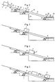
- Figure 1 shows a piece goods conveyor 1, the driven Conveyor train from a variety articulated with each other connected carriage 2, on each of which in one essential horizontal support plate 3 is an object 4 is located, either by tilting the support plate 3 Actuate a backdrop 6 in the direction of arrow 8 or by actuating another backdrop 7 in the direction of Arrow 9 are delivered to a discharge device 10 can.
- General cargo conveyors of this type are well known per se.
- Item 4 is, for example, a box, a deep-frozen one and packaged food, a household item and the same.
- the discharge device 10 has an input 18 which to the side of the conveyor and essentially on the conveyor Height is arranged. At the other end of the discharge device 10 there are several rollers 20, which have an output 19th form to remove the discharged objects 4.
- the Exit 19 is preferably arranged lower than the entrance 18. Between the input 18 and the output 19 are consecutive a trigger belt 11, a brake belt 12 and a timing belt 17th arranged on which the objects 4 from the entrance 18 to Exit 19 are promoted and explained in more detail below become.
- the take-off belt 11 is an endless belt around a drive roller 26 and a pulley 29 placed and by one Motor 23 is driven.
- the outside lla of the trigger tape 11 is comparatively strongly adhesive, such that an object thrown onto the take-off belt 11 on this does not slip and takes on the speed of the belt.
- the speed of the take-off belt 11 is, for example 2 m per second.
- the band 11 and also the other bands are of course on a not shown here Frame 32 attached.
- the brake band 12 closes directly at the end of the trigger band 11 and is also about a drive roller 27 and a deflection roller 30 is placed.
- the drive roller 27 is from driven by a motor 24.
- the tapes 11 and 12 can be by means of of an exaggeration not shown here, however, also from be driven by a single motor.
- the outside 12a the brake band 12 is slidable and thus much less adhesive than the top lla.
- the speed the brake band 12 is much smaller than that of the Trigger tape 11, preferably several times smaller, and is, for example, 0.5 m per second.
- the directions of movement of the two bands 11 and 12 are the same and in the Figure 1 indicated by arrows 13 and 14.
- a light barrier 21 is attached to the side, with the presence of an object 4 at the height this light barrier 21 can be detected. Due to corresponding Signals of the light barrier is not with one here shown control device controls the timing belt 17.
- the timing belt is around a drive roller 28 and placed around a pulley 31 and is driven by a motor 25 driven.
- the clock tape 17 is much longer than that Trigger belt 11 and the brake band 12.
- the outside 17a of the Clock tape 17 is preferably less adhesive than that of the trigger tape 11.
- a further light barrier 22 is arranged, with which the Presence of an object 4 at the end of the clock tape 17th is noticeable.
- the light barriers 21 and 22 can of course also by other suitable barriers, for example mechanically operated barriers can also be replaced.
- Figure 2 shows a carriage 2, the support plate 3 for discharge an object 4 by means of the backdrop 6 or 7 is brought into a predetermined inclined state.
- the inclination of the support plate 3 the object 4 slides in Direction of arrow 8 on the trigger belt 11 and is on this according to the speed of this belt 11 in Figure 2 promoted to the right.
- the adhesive 4 of the tape 11 can accelerate the object 4 become.
- An object projecting laterally from the band 11 4 is formed by funnel-shaped guide walls 11 aligned.
- the trigger belt 11 is preferably permanent and driven at the same speed.
- the object 4 has the lower end of the trigger belt 11 reached, he arrives at the brake band 12, which as mentioned has a comparatively slippery outside 12a and runs much slower than the trigger belt 11.
- the object slips as its speed slows down the tape 12 in the same direction and finally arrives in the position shown in Figure 3.
- the object 4 at the front end on the timing belt 17th that stands still at this time.
- FIG. 6 shows the system 1 with several discharge devices 10. As can be seen, these discharge devices 10 depending on the size of the objects 4 simple or be occupied twice. It is also possible to take turns a single or double occupancy. Of course you can the discharge devices 10 are also only partially filled become. Shown is an operator 33, a transfer device 10 removes an object 4 and one feeds further transport device 34. Because the lowest Objects on the discharge devices 10 free and are not attached to a stop, these objects can each effortlessly gripped and carried away from the rollers 10 become.
Landscapes
- Engineering & Computer Science (AREA)
- Mechanical Engineering (AREA)
- Warehouses Or Storage Devices (AREA)
- Control Of Conveyors (AREA)
- Hydroponics (AREA)
- Structure Of Belt Conveyors (AREA)
- Agricultural Chemicals And Associated Chemicals (AREA)
Claims (16)
- Installation pour préparer la commande d'articles (4) qui, au moyen d'une pluralité de chariots (2) reliés de façon articulée et comportant un plateau de support pouvant basculer latéralement (3), sont amenés sur une voie de transport d'un dispositif d'éclusage en sortie (10) associé à peu près perpendiculairement à celle-ci, le dispositif d'éclusage en sortie (10), disposé sur un plan incliné vers le bas dans la direction de transport des articles à écluser en sortie, pouvant, en une entrée (18), être chargé avec les articles (4) basculés par les chariots (2) et pouvant, en une sortie (19), être déchargé des articles (4), et, pouvant, entre l'entrée (18) et la sortie (19), être rempli avec des articles (4), caractérisée en ce que le dispositif d'éclusage en sortie (10) comporte, avant la sortie, une bande de transport synchronisée (17) et en ce qu'il est prévu, avant celle-ci, au moins une bande supplémentaire (11, 12), sur laquelle au moins un article (4) peut être positionné pour le déchargement régulé vers la bande de transport synchronisée (17).
- Installation selon la revendication 1, caractérisée en ce que la bande (12) placée avant la bande de transport synchronisée (17) est une bande de frein.
- Installation selon la revendication 1, caractérisée en ce qu'une bande de reprise (11) est disposée après l'entrée (18).
- Installation selon la revendication 3, caractérisée en ce que la bande de reprise (11) est conçue sur sa face extérieure (11a) de façon comparativement très adhésive, et en ce que la face extérieure (12a) de la bande de frein (12) est conçue de façon comparativement sensiblement moins adhésive.
- Installation selon rune des revendications 2 à 4, caractérisée en ce que la bande de frein (12) peut être mise en mouvement selon une vitesse sensiblement inférieure à celle de la bande de reprise (11).
- Installation selon l'une des revendications 3 à 5, caractérisée en ce que la bande de reprise (11) et/ou la bande de frein (12) sont sensiblement plus courtes que la bande de transport synchronisée (17).
- Installation selon l'une des revendications 1 à 6, caractérisée en ce qu'une barrière (21) est prévue avant l'entrée de la bande de transport synchronisée (17), par exemple une barrière photoélectrique, par l'intermédiaire de laquelle la présence d'au moins un article (4) avant la bande de transport synchronisée (17) peut être détectée.
- Installation selon l'une des revendications 1 à 7, caractérisée en ce qu'une barrière (22) est prévue à la sortie (19) de la bande de transport synchronisée (17), par exemple une barrière photoélectrique, par l'intermédiaire de laquelle la présence d'au moins un article (4) à la sortie (19) de la bande de transport synchronisée (17) peut être détectée.
- Installation selon l'une des revendications 1 à 8, caractérisée en ce que des parois de guidage (16) sont prévues, disposées latéralement à l'entrée (18) du dispositif d'éclusage en sortie (10).
- Installation selon l'une des revendications 1 à 9, caractérisée en ce que le convoyeur (1) peut être déchargé dans au moins deux positions se succédant dans la direction de transport, de telle sorte que le dispositif d'éclusage en sortie (10) puisse être chargé en alternance du côté gauche et du côté droit.
- Installation selon l'une des revendications 1 à 10, caractérisée en ce que le dispositif d'éclusage en sortie (10) est incliné, c'est-à-dire que l'entrée (18) est placée plus haut que la sortie (19).
- Procédé pour préparer la commande d'articles (4), qui, au moyen d'une pluralité de chariots (2) reliés de façon articulée et comportant un plateau de support pouvant basculer latéralement (3), sont amenés sur une voie de transport d'un dispositif d'éclusage en sortie (10) associé à peu près perpendiculairement à celle-ci, le dispositif d'éclusage en sortie (10), disposé sur un plan incliné vers le bas dans la direction de transport des articles à écluser en sortie, pouvant, en une entrée (18), être chargé avec les articles (4) basculés par les chariots (2) et pouvant, en une sortie (19), être déchargé des articles (4), et, pouvant, entre l'entrée (18) et la sortie (19), être rempli avec des articles (4), caractérisé en ce que les articles (4) sont placés sur le dispositif d'éclusage en sortie (10) suivant une position prédéterminée et que, depuis cette position, ils sont transportés plus avant de façon synchronisée et disposés avant la sortie (19) en au moins une rangée de prélèvement comparativement compacte.
- Procédé selon la revendication 12, caractérisé en ce que les articles (4) sont repris par un convoyeur (1) à l'entrée (18) du dispositif d'éclusage en sortie (10).
- Procédé selon la revendication 12, caractérisé en ce que les articles (4) sont freinés après le retrait.
- Procédé selon l'une des revendications 12 à 14, caractérisé en ce que les longueurs des articles (4) sont mesurées au moyen d'une barrière photoélectrique (21) par exemple et qu'ils sont synchronisés en fonction de ces mesures.
- Procédé selon l'une des revendications 12 à 15, caractérisé en ce que les articles (4) sont transportés de haut en bas.
Applications Claiming Priority (3)
| Application Number | Priority Date | Filing Date | Title |
|---|---|---|---|
| CH304394 | 1994-10-10 | ||
| CH03043/94A CH691470A5 (de) | 1994-10-10 | 1994-10-10 | Anlage und Verfahren zur Kommissionierung von Gegenständen. |
| CH3043/94 | 1994-10-10 |
Publications (2)
| Publication Number | Publication Date |
|---|---|
| EP0706960A1 EP0706960A1 (fr) | 1996-04-17 |
| EP0706960B1 true EP0706960B1 (fr) | 2000-03-01 |
Family
ID=4247344
Family Applications (1)
| Application Number | Title | Priority Date | Filing Date |
|---|---|---|---|
| EP95810619A Expired - Lifetime EP0706960B1 (fr) | 1994-10-10 | 1995-10-03 | Installation pour préparer la commande d'articles |
Country Status (6)
| Country | Link |
|---|---|
| US (1) | US5816383A (fr) |
| EP (1) | EP0706960B1 (fr) |
| AT (1) | ATE190037T1 (fr) |
| CH (1) | CH691470A5 (fr) |
| DE (1) | DE59507887D1 (fr) |
| DK (1) | DK0706960T3 (fr) |
Cited By (1)
| Publication number | Priority date | Publication date | Assignee | Title |
|---|---|---|---|---|
| DE102021106255B3 (de) | 2021-03-15 | 2022-06-15 | Interroll Holding Ag | Förderanordnung |
Families Citing this family (7)
| Publication number | Priority date | Publication date | Assignee | Title |
|---|---|---|---|---|
| US6557724B1 (en) | 2000-08-30 | 2003-05-06 | Jervis B. Webb Company | Vertical conveyor |
| US7137502B2 (en) | 2002-05-07 | 2006-11-21 | Lockheed Martin Corporation | Mail tray singulator and method of use |
| EP1382553A1 (fr) * | 2002-06-19 | 2004-01-21 | Siemens Schweiz AG | Convoyeur de séparation |
| US20050146088A1 (en) * | 2002-08-30 | 2005-07-07 | Siemens Schweiz Ag | Device for precision feeding of flat sortation items to an input device for a sorting conveyor |
| US20050191164A1 (en) * | 2002-10-23 | 2005-09-01 | Siemens Schweiz Ag | Device for effecting the positionally accurate conveyance of flat articles to be sorted to an input device for a sorting conveyor |
| DE10320961A1 (de) * | 2003-05-09 | 2004-12-09 | Siemens Ag | Fördersystem für Behälter, insbesondere eine Flughafen-Gepäckförderanlage, und eine vertikale Weiche für ein Fördersystem |
| KR20090057982A (ko) * | 2006-09-19 | 2009-06-08 | 니혼 쿄도 키카쿠 카부시키가이샤 | 물품 반송 송출 방법, 및 물품 반송 송출 장치 |
Citations (2)
| Publication number | Priority date | Publication date | Assignee | Title |
|---|---|---|---|---|
| EP0422635A1 (fr) * | 1989-10-13 | 1991-04-17 | STREAM S.r.l. | Appareil pour positionner des produits avançant en file sur une bande transporteuse |
| EP0540464A2 (fr) * | 1991-10-29 | 1993-05-05 | Müller Martini Versand-Systeme Ag | Dispositif de triage de pièces détachées |
Family Cites Families (13)
| Publication number | Priority date | Publication date | Assignee | Title |
|---|---|---|---|---|
| FR1260830A (fr) * | 1960-04-28 | 1961-05-12 | Dispositif applicable à une voie transporteuse de colis, caisses et objets analogues | |
| DE1481438A1 (de) * | 1967-03-11 | 1969-04-17 | Schade Maschf Gustav | Zuteilvorrichtung fuer Stueckgueter |
| DE2155458C3 (de) * | 1971-11-08 | 1974-09-26 | C. Keller & Co, 4533 Laggenbeck | Verfahren und Anlage zum Bereitstellen von Ziegelformlingen oder ähnlichem Stapelgut |
| US3817368A (en) * | 1972-09-08 | 1974-06-18 | American Chain & Cable Co | Automatic loading system |
| GB1412700A (en) * | 1973-06-04 | 1975-11-05 | Crisplant As | Method and apparatus for providing spacing between articles |
| US4360098A (en) * | 1977-07-29 | 1982-11-23 | Barbara Ann Nordstrom | Infeed conveyor |
| IT1117604B (it) * | 1979-02-12 | 1986-02-17 | Alisyncro S A S Di Bruno E C | Impianto per la distribuzione di prodotti alimentari particolarmente dolciari |
| IT1165189B (it) * | 1979-03-29 | 1987-04-22 | Bruno & Co Alisyncro | Dispositivo alimentatore di prodotti fra loro uguali ad una macchina confezionatrice particolarmente per prodotti dolciari |
| US4227607A (en) * | 1979-04-16 | 1980-10-14 | Malavenda Peter P | High volume method and system for dynamically storing articles for sorting and routing |
| JPS57175616A (en) * | 1981-04-23 | 1982-10-28 | Okamura Seisakusho:Kk | Method to set proper interval between loads on conveyor |
| JPS58148114A (ja) * | 1982-02-23 | 1983-09-03 | Mitsubishi Electric Corp | 電子部品の整列搬送装置 |
| US5267638A (en) * | 1989-02-16 | 1993-12-07 | Rapistan Demag Corporation | Dual-servo control for conveyor induction systems |
| US5097939A (en) * | 1989-11-03 | 1992-03-24 | Shanklin Corporation | Synchronous position product feed system |
-
1994
- 1994-10-10 CH CH03043/94A patent/CH691470A5/de not_active IP Right Cessation
-
1995
- 1995-10-03 DK DK95810619T patent/DK0706960T3/da active
- 1995-10-03 AT AT95810619T patent/ATE190037T1/de not_active IP Right Cessation
- 1995-10-03 EP EP95810619A patent/EP0706960B1/fr not_active Expired - Lifetime
- 1995-10-03 DE DE59507887T patent/DE59507887D1/de not_active Expired - Fee Related
- 1995-10-06 US US08/540,310 patent/US5816383A/en not_active Expired - Fee Related
Patent Citations (2)
| Publication number | Priority date | Publication date | Assignee | Title |
|---|---|---|---|---|
| EP0422635A1 (fr) * | 1989-10-13 | 1991-04-17 | STREAM S.r.l. | Appareil pour positionner des produits avançant en file sur une bande transporteuse |
| EP0540464A2 (fr) * | 1991-10-29 | 1993-05-05 | Müller Martini Versand-Systeme Ag | Dispositif de triage de pièces détachées |
Cited By (3)
| Publication number | Priority date | Publication date | Assignee | Title |
|---|---|---|---|---|
| DE102021106255B3 (de) | 2021-03-15 | 2022-06-15 | Interroll Holding Ag | Förderanordnung |
| WO2022194736A1 (fr) | 2021-03-15 | 2022-09-22 | Interroll Holding Ag | Agencement de transporteur |
| US12692080B2 (en) | 2021-03-15 | 2026-07-28 | Interroll Holding Ag | Conveyor arrangement |
Also Published As
| Publication number | Publication date |
|---|---|
| EP0706960A1 (fr) | 1996-04-17 |
| US5816383A (en) | 1998-10-06 |
| DK0706960T3 (da) | 2000-07-31 |
| DE59507887D1 (de) | 2000-04-06 |
| CH691470A5 (de) | 2001-07-31 |
| ATE190037T1 (de) | 2000-03-15 |
Similar Documents
| Publication | Publication Date | Title |
|---|---|---|
| DE2541813C2 (de) | Einrichtung zum Ordnen einer Anzahl ungeordnet herangeführter Behälter zu einer einzigen sich fortbewegenden Reihe | |
| DE69827411T2 (de) | Förderanlage und verfahren zu deren betrieb | |
| EP4126719B1 (fr) | Procédé pour trier des articles et dispositif de tri | |
| EP3115322B1 (fr) | Procede et dispositif destines a la depalettisation de pneus | |
| AT405640B (de) | Kommissionieranlage | |
| DE112018002335B4 (de) | Mehrstufiges Fördersystem, das Objekte in eine sequenzielle Ausrichtung neu ausrichtet | |
| DE69214122T2 (de) | Verfahren und system zum aufreihen von artikeln | |
| EP1063184B1 (fr) | Dispositif pour l'entreposage temporaire de paquets | |
| EP3670399A1 (fr) | Transporteur en cascade et procédé de tri et de transport de fermetures de récipient | |
| DE69615865T2 (de) | Förderanlage für stabförmige gegenstände | |
| CH718974A1 (de) | Vorrichtung und Verfahren zur Sequenzierung von Ladeeinheiten in einer vorbestimmten Reihenfolge. | |
| DE69510853T2 (de) | Vorrichtung zum Vereinzeln und Aufgeben einer Frucht aus Massenzufuhr | |
| EP0706960A1 (fr) | Installation pour préparer la commande d'articles | |
| DE2926792A1 (de) | Empfangsstation einer pneumatischen foerderstrecke fuer den transport von stabfoermigen artikeln der tabakverarbeitenden industrie, insbesondere von filterstaeben | |
| DE102019207724A1 (de) | Befördern von traystapeln mit einer denester-einheit | |
| EP2008953A1 (fr) | Ensemble et procédé destinés au transport d'objets | |
| EP2161226B1 (fr) | Dispositif pour le stockage d'objets rectangulaires | |
| DE3826638C2 (fr) | ||
| DE3914360C2 (fr) | ||
| DE19825328A1 (de) | Förderstreckenanordnung für mit Artikeln oder Schüttgut zu befüllende Behälter in einer Füllstation | |
| EP1147988B1 (fr) | Methode et dispositif pour le chargement et le déchargement de panniers | |
| CH695494A5 (de) | Kettenspeicher sowie Verfahren zu dessen Entladung. | |
| EP1331181A1 (fr) | Dispositif et procédé de convoyage d'objets similaires | |
| CH700129A1 (de) | Zwischenspeicher. | |
| AT362718B (de) | Einrichtung zum vereinzeln von stueckgut, insbesondere langgestrecktem stueckgut, wie schnittholz |
Legal Events
| Date | Code | Title | Description |
|---|---|---|---|
| PUAI | Public reference made under article 153(3) epc to a published international application that has entered the european phase |
Free format text: ORIGINAL CODE: 0009012 |
|
| AK | Designated contracting states |
Kind code of ref document: A1 Designated state(s): AT BE DE DK FR GB IT NL |
|
| 17P | Request for examination filed |
Effective date: 19960808 |
|
| 17Q | First examination report despatched |
Effective date: 19970205 |
|
| GRAG | Despatch of communication of intention to grant |
Free format text: ORIGINAL CODE: EPIDOS AGRA |
|
| GRAG | Despatch of communication of intention to grant |
Free format text: ORIGINAL CODE: EPIDOS AGRA |
|
| GRAH | Despatch of communication of intention to grant a patent |
Free format text: ORIGINAL CODE: EPIDOS IGRA |
|
| GRAH | Despatch of communication of intention to grant a patent |
Free format text: ORIGINAL CODE: EPIDOS IGRA |
|
| GRAA | (expected) grant |
Free format text: ORIGINAL CODE: 0009210 |
|
| AK | Designated contracting states |
Kind code of ref document: B1 Designated state(s): AT BE DE DK FR GB IT NL |
|
| PG25 | Lapsed in a contracting state [announced via postgrant information from national office to epo] |
Ref country code: NL Free format text: LAPSE BECAUSE OF FAILURE TO SUBMIT A TRANSLATION OF THE DESCRIPTION OR TO PAY THE FEE WITHIN THE PRESCRIBED TIME-LIMIT Effective date: 20000301 |
|
| REF | Corresponds to: |
Ref document number: 190037 Country of ref document: AT Date of ref document: 20000315 Kind code of ref document: T |
|
| GBT | Gb: translation of ep patent filed (gb section 77(6)(a)/1977) |
Effective date: 20000301 |
|
| REF | Corresponds to: |
Ref document number: 59507887 Country of ref document: DE Date of ref document: 20000406 |
|
| ITF | It: translation for a ep patent filed | ||
| ET | Fr: translation filed | ||
| REG | Reference to a national code |
Ref country code: DK Ref legal event code: T3 |
|
| NLV1 | Nl: lapsed or annulled due to failure to fulfill the requirements of art. 29p and 29m of the patents act | ||
| PG25 | Lapsed in a contracting state [announced via postgrant information from national office to epo] |
Ref country code: AT Free format text: LAPSE BECAUSE OF NON-PAYMENT OF DUE FEES Effective date: 20001003 |
|
| PG25 | Lapsed in a contracting state [announced via postgrant information from national office to epo] |
Ref country code: BE Free format text: LAPSE BECAUSE OF NON-PAYMENT OF DUE FEES Effective date: 20001031 |
|
| PLBE | No opposition filed within time limit |
Free format text: ORIGINAL CODE: 0009261 |
|
| STAA | Information on the status of an ep patent application or granted ep patent |
Free format text: STATUS: NO OPPOSITION FILED WITHIN TIME LIMIT |
|
| 26N | No opposition filed | ||
| REG | Reference to a national code |
Ref country code: GB Ref legal event code: 732E |
|
| BERE | Be: lapsed |
Owner name: GRAPHA-HOLDING A.G. Effective date: 20001031 |
|
| REG | Reference to a national code |
Ref country code: FR Ref legal event code: TP |
|
| REG | Reference to a national code |
Ref country code: GB Ref legal event code: IF02 |
|
| PGFP | Annual fee paid to national office [announced via postgrant information from national office to epo] |
Ref country code: GB Payment date: 20021010 Year of fee payment: 8 |
|
| PGFP | Annual fee paid to national office [announced via postgrant information from national office to epo] |
Ref country code: DK Payment date: 20021014 Year of fee payment: 8 |
|
| PGFP | Annual fee paid to national office [announced via postgrant information from national office to epo] |
Ref country code: FR Payment date: 20021023 Year of fee payment: 8 |
|
| PGFP | Annual fee paid to national office [announced via postgrant information from national office to epo] |
Ref country code: DE Payment date: 20021216 Year of fee payment: 8 |
|
| PG25 | Lapsed in a contracting state [announced via postgrant information from national office to epo] |
Ref country code: GB Free format text: LAPSE BECAUSE OF NON-PAYMENT OF DUE FEES Effective date: 20031003 |
|
| PG25 | Lapsed in a contracting state [announced via postgrant information from national office to epo] |
Ref country code: DK Free format text: LAPSE BECAUSE OF NON-PAYMENT OF DUE FEES Effective date: 20040430 |
|
| PG25 | Lapsed in a contracting state [announced via postgrant information from national office to epo] |
Ref country code: DE Free format text: LAPSE BECAUSE OF NON-PAYMENT OF DUE FEES Effective date: 20040501 |
|
| GBPC | Gb: european patent ceased through non-payment of renewal fee |
Effective date: 20031003 |
|
| REG | Reference to a national code |
Ref country code: DK Ref legal event code: EBP |
|
| PG25 | Lapsed in a contracting state [announced via postgrant information from national office to epo] |
Ref country code: FR Free format text: LAPSE BECAUSE OF NON-PAYMENT OF DUE FEES Effective date: 20040630 |
|
| REG | Reference to a national code |
Ref country code: FR Ref legal event code: ST |
|
| PG25 | Lapsed in a contracting state [announced via postgrant information from national office to epo] |
Ref country code: IT Free format text: LAPSE BECAUSE OF NON-PAYMENT OF DUE FEES;WARNING: LAPSES OF ITALIAN PATENTS WITH EFFECTIVE DATE BEFORE 2007 MAY HAVE OCCURRED AT ANY TIME BEFORE 2007. THE CORRECT EFFECTIVE DATE MAY BE DIFFERENT FROM THE ONE RECORDED. Effective date: 20051003 |