EP0706961A1 - Kassette zur Verwendung in einem pneumatischen Rohrpostsystem - Google Patents
Kassette zur Verwendung in einem pneumatischen Rohrpostsystem Download PDFInfo
- Publication number
- EP0706961A1 EP0706961A1 EP95202530A EP95202530A EP0706961A1 EP 0706961 A1 EP0706961 A1 EP 0706961A1 EP 95202530 A EP95202530 A EP 95202530A EP 95202530 A EP95202530 A EP 95202530A EP 0706961 A1 EP0706961 A1 EP 0706961A1
- Authority
- EP
- European Patent Office
- Prior art keywords
- cartridge
- segment
- conduit system
- cartridge according
- pneumatic dispatch
- Prior art date
- Legal status (The legal status is an assumption and is not a legal conclusion. Google has not performed a legal analysis and makes no representation as to the accuracy of the status listed.)
- Granted
Links
- 238000007789 sealing Methods 0.000 claims description 4
- 238000004519 manufacturing process Methods 0.000 description 1
Images
Classifications
-
- B—PERFORMING OPERATIONS; TRANSPORTING
- B65—CONVEYING; PACKING; STORING; HANDLING THIN OR FILAMENTARY MATERIAL
- B65G—TRANSPORT OR STORAGE DEVICES, e.g. CONVEYORS FOR LOADING OR TIPPING, SHOP CONVEYOR SYSTEMS OR PNEUMATIC TUBE CONVEYORS
- B65G51/00—Conveying articles through pipes or tubes by fluid flow or pressure; Conveying articles over a flat surface, e.g. the base of a trough, by jets located in the surface
- B65G51/04—Conveying the articles in carriers having a cross-section approximating that of the pipe or tube; Tube mail systems
- B65G51/06—Despatch carriers for tube mail
Definitions
- the invention relates to a cartridge for application in a pneumatic dispatch conduit system, with a basically hollow cylindrical body comprising at at least one end a closable access opening.
- the closable access opening is defined by a cover which can be screwed onto the end of the cylindrical body.
- the cover can be unscrewed and the contents of the cartridge can be removed, or objects to be transported can be put into the cartridge.
- Such cartridges are meant for a manual operation during loading and unloading.
- the cartridge according to the invention is characterized in that the access opening is defined by at least one segment which is pivotable between a closure position and an opening position, wherein means are applied for automatically pivoting the segment towards the opening position when the cartridge with its respective end is free from the pneumatic dispatch conduit system.
- the access opening is defined by at least one segment which is pivotable between a closure position and an opening position, wherein means are applied for automatically pivoting the segment towards the opening position when the cartridge with its respective end is free from the pneumatic dispatch conduit system.
- Now opening and closing of the cartridge is no longer carried out manually, because the segment defining the access opening is automatically pivoted towards the opening position by said means when the cartridge is positioned at the end of the pneumatic dispatch conduit system.
- a cartridge carried out in this way may then be applied advantageously in a pneumatic dispatch system comprising automatized loading and unloading devices for the cartridges.
- the segment is spring-loaded towards its opening position.
- said means comprise spring means which try to pivot the segment towards its opening position.
- the walls of this conduit system prevent the pivotal movement of the segment from its closure position towards its opening position; however, when the cartridge with its respective end is free from the pneumatic dispatch conduit system (and thus is positioned at an end of the pneumatic dispatch conduit system) and the segment does no longer engage the wall of the conduit system, the spring means can pivot the segment towards the opening position.
- the segment can in different ways pivot from its closure position towards its opening position and vice versa.
- the cartridge is characterized in that the segment is pivotable about a pivot-axis extending transversally to the longitudinal axis of the cylindrical body and being substantially tangent to the circumference thereof.
- the segment will automatically pivot from the closure position towards the opening position when the cartridge has reached an end of the pneumatic dispatch conduit system. Due to the mentioned special positioning of the pivot-axis of the segment however also an automatic pivoting of the segment from the opening position towards the closure position will be caused when the cartridge moves into the pneumatic dispatch conduit system. Then the end of the pneumatic dispatch conduit system engages the wall of the respective segment, such that the segment, while pivoting about the pivot-axis, is pivoted inwardly.
- pivot-axis positions of the pivot-axis are conceivable, for example a positioning of the pivot-axis in parallel with the longitudinal axis of the cylindrical body and being substantially tangent to the circumference thereof.
- end of the pneumatic dispatch conduit system cannot automatically pivot the segment from the opening position towards the closure position when the cartridge moves into the pneumatic dispatch conduit system. Therefore such an embodiment is but slightly preferred.
- the access opening is defined by at least two segments which, in the closure position, engage each other.
- the access opening is defined by more than two segments.
- edges of the segments which in the closure position engage each other and/or engage the cylindrical body comprise a labyrinth sealing. Due to such a labyrinth sealing a proper closure of the cartridge in the closure position is guaranteed.
- the cartridge according to the invention is not limited to cartridges which only at one end are provided with a closable access opening. It is possible too that a cartridge comprises at both its ends an access opening defined by at least one pivotable segment. This pivotable segment can show all the embodiments described before.
- the cartridge it can be of advantage when it comprises at least one abutment means for defining the end position of the cartridge at an end of the pneumatic dispatch conduit system.
- This abutment means can cooperate with a counter-abutment provided in the pneumatic dispatch conduit system, such that the position of the cartridge is exactly defined.
- each segment can pivot from its closure position towards its opening position.
- systems are marketed which are capable of defining the end position of the cartridges at an end of the pneumatic dispatch conduit system, such as systems comprising pairs of opposed driving belts which relative to each other are positioned in a V-shape. Because such systems are already known a detailed description is omitted here.
- the cartridge according to the invention comprises internal clamping means for clamping objects to be received such as for example a paper clip for bank notes.
- the clamping means can be activated by the segment(s). For example in the closure position the clamping means can be activated and clamp the objects to be received, whereas in the opening position the clamping means can disengage the objects to be received.
- each segment is provided with an abutment-boss which cooperates with a counter element in the pneumatic dispatch conduit system, such that through a cooperation between both elements a pivoting motion of the segment can occur.
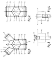
- the cartridge for application in a pneumatic dispatch conduit system illustrated in fig. 1 comprises a basically hollow cylindrical body 1 with at both ends a closable access opening 2.
- Each access opening 2 is defined by two segments 3 which can pivot about pivot axes 4 which extend transversally to the longitudinal axis of the cylindrical body 1 and which are substantially tangent to the circumference thereof (in fig. 1 perpendicularly to the plane of the drawing).
- Every segment 3 is pivotable about its respective pivot axis between a closure position (in fig. 1 shown by the segments 3 represented at the lower side) and an opening position (in fig. 1 shown by the segments 3 at the upper. side). In the opening position the internal side of the cylindrical body 1 is accessible, such that objects can be applied therein or removed therefrom.
- the segments 3 belonging to one and the same access opening 2 have, in the embodiment illustrated, each a semi-cylindrical shape. In the closure position the segments engage each other such that they in a way define an elongation of the cylindrical body 1.
- the segments 3 define a guiding ring 5 which, when the cartridge is positioned in a pneumatic dispatch conduit system, will engage the internal wall of the pneumatic dispatch conduit system.
- a guiding ring generally comprises a material having a low friction and sound absorbing capacities, such as felt.
- the dimensions of the guiding rings 5 are such that the segments 3, when the cartridge is received in the pneumatic dispatch conduit system, are maintained exactly in the closure position. This position is represented in fig. 2, in which the cartridge is fully closed. For bringing this closure position into perfection it is possible that the edges of the segments which in the closure position engage each other and/or engage the cylindrical body (for example in fig. 1 indicated with reference number 6, 7 and 8) are provided with a labyrinth sealing.
- a cartridge according to the invention is kept in such a position that the segments 3 at the upper side can take in the opening position. In this position loading or unloading (manually or automatically) can occur.
- both segments 3 will pivot to the closure position about their respective pivot axis 4 and against the force of the spring means, such that the situation illustrated in fig. 4 is obtained in which the cartridge is fully closed and is being conveyed through the pneumatic dispatch conduit system.
- abutment means may be applied, or driving belts known already, which are positioned relative to each other in a V-shape.
Landscapes
- Physics & Mathematics (AREA)
- Engineering & Computer Science (AREA)
- Fluid Mechanics (AREA)
- Mechanical Engineering (AREA)
- Quick-Acting Or Multi-Walled Pipe Joints (AREA)
- Infusion, Injection, And Reservoir Apparatuses (AREA)
Applications Claiming Priority (2)
| Application Number | Priority Date | Filing Date | Title |
|---|---|---|---|
| NL9401684A NL9401684A (nl) | 1994-10-12 | 1994-10-12 | Patroon voor toepassing in een buispostleidingsysteem. |
| NL9401684 | 1994-10-12 |
Publications (2)
| Publication Number | Publication Date |
|---|---|
| EP0706961A1 true EP0706961A1 (de) | 1996-04-17 |
| EP0706961B1 EP0706961B1 (de) | 1998-08-12 |
Family
ID=19864766
Family Applications (1)
| Application Number | Title | Priority Date | Filing Date |
|---|---|---|---|
| EP95202530A Expired - Lifetime EP0706961B1 (de) | 1994-10-12 | 1995-09-19 | Kassette zur Verwendung in einem pneumatischen Rohrpostsystem |
Country Status (4)
| Country | Link |
|---|---|
| EP (1) | EP0706961B1 (de) |
| AT (1) | ATE169591T1 (de) |
| DE (1) | DE69504002T2 (de) |
| NL (1) | NL9401684A (de) |
Cited By (2)
| Publication number | Priority date | Publication date | Assignee | Title |
|---|---|---|---|---|
| EP0731042A1 (de) * | 1995-03-08 | 1996-09-11 | Ergon Trans B.V. | Station für eine Rohrpostanlage |
| AT519320A1 (de) * | 2016-11-08 | 2018-05-15 | Ing Sumetzberger Gmbh | Rohrposthülse |
Citations (2)
| Publication number | Priority date | Publication date | Assignee | Title |
|---|---|---|---|---|
| WO1984000945A1 (en) * | 1982-08-25 | 1984-03-15 | Partek Ab | A shuttle for the transfer of a fluid substance by means of a pressure difference in a tube, between a filling station and an emptying station, and a device for filling and/or emptying the shuttle |
| DE3313676A1 (de) * | 1983-04-15 | 1984-10-25 | GCT GRAU-COMMUNICATIONS TECHNOLOGY GmbH & Co, 7053 Kernen | Transportbuechse fuer rohrpostanlagen |
-
1994
- 1994-10-12 NL NL9401684A patent/NL9401684A/nl not_active Application Discontinuation
-
1995
- 1995-09-19 AT AT95202530T patent/ATE169591T1/de not_active IP Right Cessation
- 1995-09-19 DE DE69504002T patent/DE69504002T2/de not_active Expired - Fee Related
- 1995-09-19 EP EP95202530A patent/EP0706961B1/de not_active Expired - Lifetime
Patent Citations (2)
| Publication number | Priority date | Publication date | Assignee | Title |
|---|---|---|---|---|
| WO1984000945A1 (en) * | 1982-08-25 | 1984-03-15 | Partek Ab | A shuttle for the transfer of a fluid substance by means of a pressure difference in a tube, between a filling station and an emptying station, and a device for filling and/or emptying the shuttle |
| DE3313676A1 (de) * | 1983-04-15 | 1984-10-25 | GCT GRAU-COMMUNICATIONS TECHNOLOGY GmbH & Co, 7053 Kernen | Transportbuechse fuer rohrpostanlagen |
Cited By (4)
| Publication number | Priority date | Publication date | Assignee | Title |
|---|---|---|---|---|
| EP0731042A1 (de) * | 1995-03-08 | 1996-09-11 | Ergon Trans B.V. | Station für eine Rohrpostanlage |
| AT519320A1 (de) * | 2016-11-08 | 2018-05-15 | Ing Sumetzberger Gmbh | Rohrposthülse |
| WO2018085871A1 (de) * | 2016-11-08 | 2018-05-17 | Ing. Sumetzberger Gmbh | Rohrposthülse |
| US10562719B2 (en) | 2016-11-08 | 2020-02-18 | Ing. Sumetzberger Gmbh | Pneumatic-tube container |
Also Published As
| Publication number | Publication date |
|---|---|
| ATE169591T1 (de) | 1998-08-15 |
| EP0706961B1 (de) | 1998-08-12 |
| DE69504002T2 (de) | 1999-04-15 |
| DE69504002D1 (de) | 1998-09-17 |
| NL9401684A (nl) | 1996-05-01 |
Similar Documents
| Publication | Publication Date | Title |
|---|---|---|
| US2752106A (en) | Gauze holder | |
| EP0517465A1 (de) | Schelle für Rohre und Kabel | |
| GB2137960A (en) | Portable hose-reel | |
| GB9705743D0 (en) | A packaging material web for a self-supporting packaging container wall, and packaging containers made from the web | |
| CA2229469A1 (en) | Apparatus for supporting pipes | |
| US5005341A (en) | Apparatus for filling sacks | |
| FI964055A7 (fi) | Laite säiliön ripustamista varten sekä annostelulaite, jossa on mainittu säiliö | |
| FR2736029B1 (fr) | Wagon de stockage pour le stockage de matieres en vrac | |
| EP0706961A1 (de) | Kassette zur Verwendung in einem pneumatischen Rohrpostsystem | |
| GR3021899T3 (en) | Loading device for containers or the like | |
| FR2750396B1 (fr) | Etui de rebouchage d'un recipient muni d'un obturateur frangible utilisable comme vecteur de communication | |
| US4483458A (en) | Closure system for pressure vessels | |
| US6679378B1 (en) | Device for storing and transporting flat objects | |
| US6971822B2 (en) | Device for distributing and receiving articles in the form of sheets of paper, particularly banknotes, documents and the like | |
| US1086423A (en) | Automatic file or binder. | |
| US1613471A (en) | Pneumatic dispatch carrier | |
| GB2293596B (en) | Container having improved means for loading the container with loose solid goods | |
| FR2723916B3 (fr) | Dispositif de rangement suspendu, en particulier pour conteneur de transport | |
| ZA972108B (en) | Bulk material handling vehicle. | |
| CA2278304A1 (en) | Transportable film dispenser device | |
| EP0661586A3 (en) | Device for loading and unloading a film cartridge. | |
| ATE277320T1 (de) | Verwendung eines verbindungselements für flansche an behältermündungen von laborgeräten | |
| SG91833A1 (en) | Container loading/unloading system for a multilevel depot | |
| DE69530560D1 (de) | Vorratsbehälter für Filmpatronen | |
| RU1833344C (en) | Winding device for flexible flat articles |
Legal Events
| Date | Code | Title | Description |
|---|---|---|---|
| PUAI | Public reference made under article 153(3) epc to a published international application that has entered the european phase |
Free format text: ORIGINAL CODE: 0009012 |
|
| AK | Designated contracting states |
Kind code of ref document: A1 Designated state(s): AT BE DE GB IT NL |
|
| 17P | Request for examination filed |
Effective date: 19960917 |
|
| 17Q | First examination report despatched |
Effective date: 19970502 |
|
| GRAG | Despatch of communication of intention to grant |
Free format text: ORIGINAL CODE: EPIDOS AGRA |
|
| GRAG | Despatch of communication of intention to grant |
Free format text: ORIGINAL CODE: EPIDOS AGRA |
|
| GRAH | Despatch of communication of intention to grant a patent |
Free format text: ORIGINAL CODE: EPIDOS IGRA |
|
| GRAH | Despatch of communication of intention to grant a patent |
Free format text: ORIGINAL CODE: EPIDOS IGRA |
|
| RAP3 | Party data changed (applicant data changed or rights of an application transferred) |
Owner name: ERGOTRANS B.V. |
|
| GRAA | (expected) grant |
Free format text: ORIGINAL CODE: 0009210 |
|
| RAP1 | Party data changed (applicant data changed or rights of an application transferred) |
Owner name: ERGOTRANS B.V. |
|
| AK | Designated contracting states |
Kind code of ref document: B1 Designated state(s): AT BE DE GB IT NL |
|
| REF | Corresponds to: |
Ref document number: 169591 Country of ref document: AT Date of ref document: 19980815 Kind code of ref document: T |
|
| REF | Corresponds to: |
Ref document number: 69504002 Country of ref document: DE Date of ref document: 19980917 |
|
| PLBE | No opposition filed within time limit |
Free format text: ORIGINAL CODE: 0009261 |
|
| STAA | Information on the status of an ep patent application or granted ep patent |
Free format text: STATUS: NO OPPOSITION FILED WITHIN TIME LIMIT |
|
| 26N | No opposition filed | ||
| PGFP | Annual fee paid to national office [announced via postgrant information from national office to epo] |
Ref country code: BE Payment date: 20010814 Year of fee payment: 7 |
|
| PGFP | Annual fee paid to national office [announced via postgrant information from national office to epo] |
Ref country code: NL Payment date: 20010927 Year of fee payment: 7 |
|
| REG | Reference to a national code |
Ref country code: GB Ref legal event code: IF02 |
|
| PGFP | Annual fee paid to national office [announced via postgrant information from national office to epo] |
Ref country code: GB Payment date: 20020909 Year of fee payment: 8 |
|
| PGFP | Annual fee paid to national office [announced via postgrant information from national office to epo] |
Ref country code: DE Payment date: 20020926 Year of fee payment: 8 |
|
| PGFP | Annual fee paid to national office [announced via postgrant information from national office to epo] |
Ref country code: AT Payment date: 20020927 Year of fee payment: 8 |
|
| PG25 | Lapsed in a contracting state [announced via postgrant information from national office to epo] |
Ref country code: BE Free format text: LAPSE BECAUSE OF NON-PAYMENT OF DUE FEES Effective date: 20020930 |
|
| BERE | Be: lapsed |
Owner name: *ERGOTRANS B.V. Effective date: 20020930 |
|
| PG25 | Lapsed in a contracting state [announced via postgrant information from national office to epo] |
Ref country code: NL Free format text: LAPSE BECAUSE OF NON-PAYMENT OF DUE FEES Effective date: 20030401 |
|
| PG25 | Lapsed in a contracting state [announced via postgrant information from national office to epo] |
Ref country code: GB Free format text: LAPSE BECAUSE OF NON-PAYMENT OF DUE FEES Effective date: 20030919 Ref country code: AT Free format text: LAPSE BECAUSE OF NON-PAYMENT OF DUE FEES Effective date: 20030919 |
|
| PG25 | Lapsed in a contracting state [announced via postgrant information from national office to epo] |
Ref country code: DE Free format text: LAPSE BECAUSE OF NON-PAYMENT OF DUE FEES Effective date: 20040401 |
|
| GBPC | Gb: european patent ceased through non-payment of renewal fee |
Effective date: 20030919 |
|
| PG25 | Lapsed in a contracting state [announced via postgrant information from national office to epo] |
Ref country code: IT Free format text: LAPSE BECAUSE OF NON-PAYMENT OF DUE FEES Effective date: 20050919 |