EP0707216A2 - Method and clip-on current probe for determining the compensation capacity of an electrical network - Google Patents
Method and clip-on current probe for determining the compensation capacity of an electrical network Download PDFInfo
- Publication number
- EP0707216A2 EP0707216A2 EP95402282A EP95402282A EP0707216A2 EP 0707216 A2 EP0707216 A2 EP 0707216A2 EP 95402282 A EP95402282 A EP 95402282A EP 95402282 A EP95402282 A EP 95402282A EP 0707216 A2 EP0707216 A2 EP 0707216A2
- Authority
- EP
- European Patent Office
- Prior art keywords
- values
- determined
- time
- compensation capacity
- value
- Prior art date
- Legal status (The legal status is an assumption and is not a legal conclusion. Google has not performed a legal analysis and makes no representation as to the accuracy of the status listed.)
- Withdrawn
Links
Images


Classifications
-
- G—PHYSICS
- G01—MEASURING; TESTING
- G01R—MEASURING ELECTRIC VARIABLES; MEASURING MAGNETIC VARIABLES
- G01R21/00—Arrangements for measuring electric power or power factor
- G01R21/133—Arrangements for measuring electric power or power factor by using digital technique
- G01R21/1331—Measuring real or reactive component, measuring apparent energy
-
- G—PHYSICS
- G01—MEASURING; TESTING
- G01R—MEASURING ELECTRIC VARIABLES; MEASURING MAGNETIC VARIABLES
- G01R19/00—Arrangements for measuring currents or voltages or for indicating presence or sign thereof
- G01R19/25—Arrangements for measuring currents or voltages or for indicating presence or sign thereof using digital measurement techniques
- G01R19/2513—Arrangements for monitoring electric power systems, e.g. power lines or loads; Logging
Definitions
- the present invention relates to a method for determining the value of a compensation capacity intended for an electrical network.
- the problem underlying the invention is to provide the simplest possible method, and a device, for determining the compensation capacity necessary for an electrical network by taking into account the residual phase shift.
- the subject of the present invention is a method for determining the value of a compensation capacity, Cc, intended for an electrical network, characterized in that, in real time and with rapid sampling, the measured variables for current and voltage are digitized, the period, T, of the signals, the active consumption, Wa, and the reactive consumption, Wr, during a predetermined period of time, N.ts, as well as the sum of the squares of the voltage, ⁇ U, during the same period of time, a set value is entered, ⁇ c, for the angular phase shift, ⁇ , remaining during the introduction of the compensation capacity into the electrical network and the compensation capacity is determined from the temporarily stored values T, Wa, Wr, ⁇ U, and from the set value, ⁇ c , Cc, according to the following formula: in which k is a normalization constant, ts is the time interval separating two sampling values during the digitization and N is the number of the sampling values obtained in said determined period of time, N. ts.
- the setpoint value, ⁇ c, entered for the residual phase shift, ⁇ makes it easier for the user to find the suitable compensation capacity since this allows, for example, to successively enter a setpoint value, ⁇ c , zero as well as a set value, ⁇ c, which differs from this zero value and which corresponds to the residual phase shift, ⁇ , maximum allowed or expected and to find a combination of capacitors with normalized values between the two compensation capacities which have been determined from these setpoints, ⁇ c.
- a clamp device current clamp
- the current is measured by closing the measuring clamp on the conductor on which the measurement is to be made and the voltage is measured by connecting additional voltage measurement inputs to the conductors on which the measurement is to be made
- the measurement values are digitized by means of at least one analog-digital converter
- the period is determined from the digitized sampling values , T, signals, active consumption, Wa, and reactive consumption, Wr, during a predetermined period of time, N.ts, as well as the sum of the squares of the voltage, ⁇ U, during the same period of time, these values are temporarily stored in a buffer memory
- a set value, ⁇ c, for angular phase shift, ⁇ , subsistan is entered by means of control elements of the clamp device t during the introduction of the compensation capacity, Cc, into the electrical network and, from the temporarily stored values, T, Wa, Wr, ⁇ U, and from the reference value, ⁇ c, the capacity is determined compensation, Cc, according to
- a conductor is enclosed in the measurement clamp of the clamp apparatus.
- a current input 14 which amplifies the voltage signal supplied by the Hall effect element of the measurement clamp, a measurement voltage Ui proportional to the measured current reaches a first input of a multiplexer 16.
- a second input of the multiplexer 16 is connected to the output of a voltage input terminal 18 whose input is, in turn, connected to the two conductors of the electrical network R and which provides a second measurement voltage Uu proportional to the measured voltage.
- the output of the multiplexer 16 is connected to the input of an analog-digital converter 20 which, at predetermined fixed time intervals, synchronously with the multiplexer 16, transforms the instantaneous value of each of the values of the voltage Ui, respectively Uu, into a digital value and transmits this digital value to a digital signal processor 22.
- summation values represent intermediate results intended for the determination, which is then carried out, of the active consumption, Wa, and of the reactive consumption, Wr, according to known calculation methods which are executed in real time by the digital processor of signals 22.
- the summation values are sent cyclically, for example every 0.5 seconds to a microprocessor 24 which calculates the active consumption, Wa, and the reactive consumption, Wr, from these summation values.
- This calculation is not as critical as the calculation of the summation values and can therefore be carried out by a usual microprocessor which can, moreover, take on additional tasks such as the control of a display 26 and the interrogation of control elements, such as the system control of the clamp device.
- the values supplied by the microprocessor 24 for the active consumption, Wa, and the reactive consumption, Wr, and the period, T, determined by the zero crossings of the signals as well as the sum ⁇ U 2 n are stored in a buffer memory 28.
- the compensation capacity Cc is calculated and displayed on the display 26.
- FIG. 2 is an operating diagram for such a determination of the compensation capacity, Cc.
- an input terminal 140 provides digitized sampling values of the measured current, I, and a second input terminal 180 provides digitized sampling values of the measured voltage, U. These values are sent to a sum formation step 200 which elaborates the sums indicated above cyclically, each time for a number N, transmitted by another input, of sampling values.
- the sums thus obtained are used cyclically (N.ts) for the calculation of active consumption, Wa, and reactive consumption, Wr ,.
- the period, T is determined from the zero crossings of the signals.
- these values are recorded, also cyclically, in a buffer memory or received in the buffer memory 240 under the control of a signal applied to a control input S.
- the compensation capacity, Cc is calculated in block 260 using the values stored in buffer 240 and the phase shift value stored in setpoint memory 280, ⁇ c ,.
- the value entered in this setpoint memory 280 is monitored for its variations by a comparator 300 and it can be either loaded directly with digital values by means of elements of control of the measuring clamp (not shown), or the content can be constantly modified by means of an up-down counter signal with corresponding logic.
- a new calculation is triggered either by a modification of the set value, ⁇ c, detected by the comparator 300 and which is signaled by the signal Ms at block 260, or by new measurements received in the buffer memory and which are signaled by the Mw signal at block 260.
- the sampling period, ts can be adjusted between 61 microseconds and 15.6 milliseconds (for a pair of current / voltage samples) and the number of samples, N, can be adjusted by 1 to 8192 according to the frequency of the measured signals.
Landscapes
- Engineering & Computer Science (AREA)
- Power Engineering (AREA)
- Physics & Mathematics (AREA)
- General Physics & Mathematics (AREA)
- Measurement Of Current Or Voltage (AREA)
Abstract
Description
La présente invention concerne un procédé pour la détermination de la valeur d'une capacité de compensation destinée à un réseau électrique.The present invention relates to a method for determining the value of a compensation capacity intended for an electrical network.
Les réseaux électriques à moyenne et haute tension, en particulier ceux se trouvant à l'intérieur d'une entreprise, sont, dans la plupart des cas, à charge inductive si bien qu'il y a la nécessité de compenser, de manière localisée ou centralisée, le déphasage entre le courant et la tension qui en résulte au moyen de capacités de compensation correspondantes.Medium and high voltage electrical networks, in particular those located within a company, are, in most cases, inductive charging so that there is the need to compensate, locally or centralized, the phase shift between the current and the resulting voltage by means of corresponding compensation capacitors.
Le but théorique de la compensation est d'obtenir un déphasage nul, mais, dans la pratique, ceci est rarement atteint car les conditions de charge à l'intérieur d'une entreprise varient en permanence. En outre, on ne dispose que de condensateurs dont les valeurs des capacités ne peuvent être choisies que dans une série de valeurs normalisées et il n'est pas possible de prendre une combinaison de ces valeurs normalisées pour obtenir une capacité donnant un déphasage nul pour des raisons de coût et d'encombrement.The theoretical aim of compensation is to obtain zero phase shift, but in practice this is rarely achieved because the load conditions within a company vary constantly. In addition, there are only capacitors whose capacitance values can only be chosen from a series of normalized values and it is not possible to take a combination of these normalized values to obtain a capacitance giving zero phase shift for reasons of cost and size.
Cela conduit dans la pratique à déterminer, à partir d'un déphasage non compensé mesuré, une capacité de compensation de consigne qui est introduite dans le réseau électrique et, à partir d'une nouvelle mesure basée sur le déphasage subsistant, on introduit la valeur normalisée la plus proche dans le réseau électrique.This leads in practice to determining, from a measured non-compensated phase shift, a setpoint compensation capacity which is introduced into the electrical network and, from a new measurement based on the remaining phase shift, the value is introduced. closest standard in the electrical network.
Le problème à la base de l'invention est de fournir un procédé le plus simple possible, et un dispositif, pour la détermination de la capacité de compensation nécessaire pour un réseau électrique en prenant en compte le déphasage résiduel.The problem underlying the invention is to provide the simplest possible method, and a device, for determining the compensation capacity necessary for an electrical network by taking into account the residual phase shift.
A cet effet, la présente invention a pour objet un procédé pour la détermination de la valeur d'une capacité de compensation, Cc, destinée à un réseau électrique, caractérisé en ce que, en temps réel et avec un échantillonnage rapide, on numérise les grandeurs de mesure pour le courant et la tension, on détermine et on mémorise de manière temporaire la période, T, des signaux, la consommation active, Wa, et la consommation réactive, Wr, pendant un laps de temps prédéterminé, N.ts, ainsi que la somme des carrés de la tension, ΣU, pendant le même laps de temps, on entre une valeur de consigne, ϕc, pour le déphasage angulaire, ϕ, subsistant lors de l'introduction de la capacité de compensation dans le réseau électrique et on détermine, à partir des valeurs mémorisées de manière temporaire, T, Wa, Wr, ΣU, et de la valeur de consigne, ϕc, la capacité de compensation, Cc, selon la formule suivante:
En particulier, la valeur de consigne, ϕc, entrée pour le déphasage résiduel, ϕ, permet à l'utilisateur de trouver plus facilement la capacité de compensation qui convient car cela permet, par exemple, d'entrer successivement une valeur de consigne, ϕc, nulle ainsi qu'une valeur de consigne, ϕc, qui diffère de cette valeur nulle et qui correspond au déphasage résiduel, ϕ, maximal permis ou prévu et de trouver une combinaison de condensateurs de valeurs normalisées se trouvant entre les deux capacités de compensation qui ont été déterminées à partir de ces valeurs de consigne, ϕc.In particular, the setpoint value, ϕc, entered for the residual phase shift, ϕ, makes it easier for the user to find the suitable compensation capacity since this allows, for example, to successively enter a setpoint value, ϕc , zero as well as a set value, ϕc, which differs from this zero value and which corresponds to the residual phase shift, ϕ, maximum allowed or expected and to find a combination of capacitors with normalized values between the two compensation capacities which have been determined from these setpoints, ϕc.
Il est particulièrement avantageux de mettre en oeuvre ce procédé dans un appareil à pince (pince ampèremétrique), dans lequel on mesure le courant en fermant la pince de mesure sur le conducteur sur lequel on doit faire la mesure et on mesure la tension en reliant des entrées additionnelles de mesure de tension aux conducteurs sur lesquels on doit faire la mesure, la numérisation des valeurs de mesure est réalisée au moyen d'au moins un convertisseur analogique-numérique, on détermine, à partir des valeurs d'échantillonnage numérisées, la période, T, des signaux, la consommation active, Wa, et la consommation réactive, Wr, pendant un laps de temps prédéterminé, N.ts, ainsi que la somme des carrés de la tension, ΣU, pendant le même laps de temps, ces valeurs sont mémorisées de manière temporaire dans une mémoire tampon, on entre, au moyen d'éléments de commande de l'appareil à pince, une valeur de consigne, ϕc, pour le déphasage angulaire, ϕ, subsistant lors de l'introduction de la capacité de compensation, Cc, dans le réseau électrique et on détermine, à partir des valeurs mémorisées de manière temporaire, T, Wa, Wr, ΣU, et de la valeur de consigne, ϕc, la capacité de compensation, Cc, selon la formule suivante: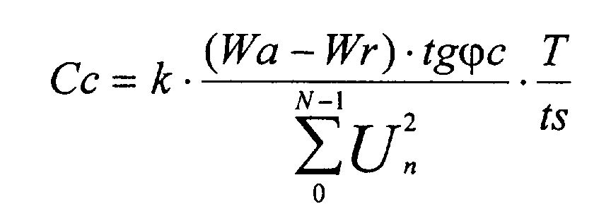
D'autres caractéristiques et avantages de l'invention ressortiront de la description qui suit, faite à titre illustratif et nullement limitatif, en se référant aux dessins annexés dans lesquels :
- la figure 1 est un schéma synoptique du traitement des signaux d'un appareil à pince (pince ampèremétrique), et
- la figure 2 est un diagramme de fonctionnement pour la détermination de la capacité de compensation.
- FIG. 1 is a block diagram of the processing of signals from a clamp device (current clamp), and
- FIG. 2 is an operating diagram for determining the compensation capacity.
Pour la mesure des grandeurs électriques d'un réseau électrique R comportant une charge 12 qui est composée de charges résistives et de charges inductives, un conducteur est enfermé dans la pince de mesure de l'appareil à pince. Au moyen d'une entrée de courant 14 qui amplifie le signal en tension fourni par l'élément à effet Hall de la pince de mesure, une tension de mesure Ui proportionnelle au courant mesuré parvient à une première entrée d'un multiplexeur 16. Une deuxième entrée du multiplexeur 16 est reliée à la sortie d'une borne d'entrée de tension 18 dont l'entrée est, à son tour, reliée aux deux conducteurs du réseau électrique R et qui fournit une deuxième tension de mesure Uu proportionnelle à la tension mesurée.For the measurement of the electrical quantities of an electrical network R comprising a
La sortie du multiplexeur 16 est reliée à l'entrée d'un convertisseur analogique-numérique 20 qui, à des intervalles de temps fixes prédéterminés, de manière synchrone avec le multiplexeur 16, transforme la valeur instantanée de chacune des valeurs de la tension Ui, respectivement Uu, en une valeur numérique et transmet cette valeur numérique à un processeur numérique de signaux 22.The output of the
Dans ce processeur numérique de signaux 22, qui est particulièrement adapté au traitement rapide des signaux et peut donc exécuter plusieurs étapes de calcul entre des valeurs numériques successives de Ui et de Uu, en prenant en compte la linéarisation et la correction de zéro connues d'après le document EP-A-0.263.154, on forme les sommations cycliques suivantes de n = 0 à N-1 afin de déterminer les grandeurs électriques:
Ces valeurs de sommations représentent des résultats intermédiaires destinés à la détermination, qui est réalisée ensuite, de la consommation active, Wa, et de la consommation réactive, Wr, selon des procédés de calcul connus qui sont exécutés en temps réel par le processeur numérique de signaux 22. Les valeurs de sommation sont envoyées de manière cyclique, par exemple toutes les 0,5 seconde à un microprocesseur 24 qui calcule la consommation active, Wa, et la consommation réactive, Wr, à partir de ces valeurs de sommation. Ce calcul n'est pas aussi critique que le calcul des valeurs de sommation et peut donc être effectué par un microprocesseur usuel qui peut, en outre, prendre en charge des tâches supplémentaires telles que la commande d'un afficheur 26 et l'interrogation d'éléments de commande, tels que la commande du système de l'appareil à pince.These summation values represent intermediate results intended for the determination, which is then carried out, of the active consumption, Wa, and of the reactive consumption, Wr, according to known calculation methods which are executed in real time by the digital processor of signals 22. The summation values are sent cyclically, for example every 0.5 seconds to a
Les valeurs fournies par le microprocesseur 24 pour la consommation active, Wa, et la consommation réactive, Wr, et la période, T, déterminée par les passages à zéro des signaux ainsi que la somme ΣU2 n sont mémorisées dans une mémoire tampon 28.The values supplied by the
A partir des valeurs mémorisées et en utilisant la formule suivante:
La figure 2 est un diagramme de fonctionnement pour une telle détermination de la capacité de compensation, Cc.FIG. 2 is an operating diagram for such a determination of the compensation capacity, Cc.
A des intervalles de temps égaux à ts, une borne d'entrée 140 fournit des valeurs d'échantillonnage numérisées du courant mesuré, I, et une deuxième borne d'entrée 180 fournit des valeurs d'échantillonnage numérisées de la tension mesurée, U. Ces valeurs sont envoyées à une étape de formation de sommes 200 qui élabore les sommes indiquées plus haut de manière cyclique, à chaque fois pour un nombre N, transmis par une autre entrée, de valeurs d'échantillonnage.At time intervals equal to ts, an
Les sommes ainsi obtenues sont utilisées de manière cyclique (N.ts) pour le calcul de la consommation active, Wa, et de la consommation réactive, Wr,. De plus, la période, T, est déterminée à partir des passages à zéro des signaux.The sums thus obtained are used cyclically (N.ts) for the calculation of active consumption, Wa, and reactive consumption, Wr ,. In addition, the period, T, is determined from the zero crossings of the signals.
En fonction du mode fixé pour le procédé, ces valeurs sont enregistrées, également de manière cyclique, dans une mémoire tampon ou reçues dans la mémoire tampon 240 sous la commande d'un signal appliqué à une entrée de commande S.Depending on the mode set for the method, these values are recorded, also cyclically, in a buffer memory or received in the
Le calcul de la capacité de compensation, Cc, s'effectue dans le bloc 260 en utilisant les valeurs mémorisées dans la mémoire tampon 240 et la valeur de déphasage mémorisée dans une mémoire 280 de valeur de consigne, ϕc,. La valeur inscrite dans cette mémoire 280 de valeur de consigne est surveillée en ce qui concerne ses variations par un comparateur 300 et elle peut être soit chargée directement avec des valeurs numériques au moyen d'éléments de commande de la pince de mesure (non représentés), soit le contenu peut être modifié constamment au moyen d'un signal de compteur-décompteur avec une logique correspondante.The compensation capacity, Cc, is calculated in
Un nouveau calcul est déclenché soit par une modification de la valeur de consigne, ϕc, détectée par le comparateur 300 et qui est signalée par le signal Ms au bloc 260, soit par de nouvelles mesures parvenues dans la mémoire tampon et qui sont signalées par le signal Mw au bloc 260.A new calculation is triggered either by a modification of the set value, ϕc, detected by the
En fonction des dimensions et de la structure de l'afficheur 26 utilisé, on peut représenter la valeur de consigne, ϕc, et la capacité de compensation, Cc, simultanément ou au choix.Depending on the dimensions and the structure of the
Dans un exemple de réalisation, la période d'échantillonnage, ts, peut être ajustée entre 61 microsecondes et 15,6 millisecondes (pour un couple d'échantillons courant/tension) et le nombre d'échantillons, N, peut être ajusté de 1 à 8192 selon la fréquence des signaux mesurés.In an exemplary embodiment, the sampling period, ts, can be adjusted between 61 microseconds and 15.6 milliseconds (for a pair of current / voltage samples) and the number of samples, N, can be adjusted by 1 to 8192 according to the frequency of the measured signals.
Claims (11)


Applications Claiming Priority (2)
| Application Number | Priority Date | Filing Date | Title |
|---|---|---|---|
| DE4436593 | 1994-10-13 | ||
| DE19944436593 DE4436593A1 (en) | 1994-10-13 | 1994-10-13 | Procedure for determining a compensation capacity |
Publications (2)
| Publication Number | Publication Date |
|---|---|
| EP0707216A2 true EP0707216A2 (en) | 1996-04-17 |
| EP0707216A3 EP0707216A3 (en) | 1996-09-25 |
Family
ID=6530671
Family Applications (1)
| Application Number | Title | Priority Date | Filing Date |
|---|---|---|---|
| EP95402282A Withdrawn EP0707216A3 (en) | 1994-10-13 | 1995-10-13 | Method and clip-on current probe for determining the compensation capacity of an electrical network |
Country Status (2)
| Country | Link |
|---|---|
| EP (1) | EP0707216A3 (en) |
| DE (1) | DE4436593A1 (en) |
Cited By (2)
| Publication number | Priority date | Publication date | Assignee | Title |
|---|---|---|---|---|
| CN108832715A (en) * | 2018-06-14 | 2018-11-16 | 张作夷 | Electric system based on current waveform real-time monitoring |
| CN113740657A (en) * | 2021-11-04 | 2021-12-03 | 国网江西省电力有限公司电力科学研究院 | Method and system for online checking capacity of single high-power-supply high-count distribution transformer |
Families Citing this family (1)
| Publication number | Priority date | Publication date | Assignee | Title |
|---|---|---|---|---|
| DE102020115180A1 (en) * | 2020-06-08 | 2021-12-09 | Turck Holding Gmbh | Energy measuring terminal or measuring circuit of an energy measuring terminal |
Family Cites Families (3)
| Publication number | Priority date | Publication date | Assignee | Title |
|---|---|---|---|---|
| CA1106916A (en) * | 1978-06-20 | 1981-08-11 | H.O.P. Consulab Inc. | Apparatus and method to regulate the power factor of an electrical distribution line |
| US4645997A (en) * | 1985-03-13 | 1987-02-24 | Kollmorgen Technologies Corporation | Transient free solid state automatic power factor correction |
| JPS6287871A (en) * | 1985-10-15 | 1987-04-22 | Toshiba Corp | Reactive power tide measuring apparatus |
-
1994
- 1994-10-13 DE DE19944436593 patent/DE4436593A1/en not_active Ceased
-
1995
- 1995-10-13 EP EP95402282A patent/EP0707216A3/en not_active Withdrawn
Non-Patent Citations (1)
| Title |
|---|
| None |
Cited By (2)
| Publication number | Priority date | Publication date | Assignee | Title |
|---|---|---|---|---|
| CN108832715A (en) * | 2018-06-14 | 2018-11-16 | 张作夷 | Electric system based on current waveform real-time monitoring |
| CN113740657A (en) * | 2021-11-04 | 2021-12-03 | 国网江西省电力有限公司电力科学研究院 | Method and system for online checking capacity of single high-power-supply high-count distribution transformer |
Also Published As
| Publication number | Publication date |
|---|---|
| EP0707216A3 (en) | 1996-09-25 |
| DE4436593A1 (en) | 1996-04-25 |
Similar Documents
| Publication | Publication Date | Title |
|---|---|---|
| EP0772055B1 (en) | System for controlling the discharge phase of charge/discharge cycles of a rechargeable battery and host device including an intelligent battery | |
| EP2755848B1 (en) | Method of monitoring the capacitive filter of a battery charger | |
| EP2362234B1 (en) | Non-intrusive method for determination of the electrical impedance of a battery | |
| EP0603088B1 (en) | Device for numerical calculation of a symmetrical component of an electric quantity in a three-phase network and relay comprising the same | |
| FR2999721B1 (en) | METHOD AND DEVICE FOR CHARACTERIZING A CAPACITIVE EFFECT ENERGY STORAGE MODULE | |
| EP0554424B1 (en) | Method for identifying electrical power consumers on a circuit being monitored | |
| FR2872913A1 (en) | METHOD FOR DETERMINING ACTIVE COMPONENTS AND REACTIVATING THE LOOP IMPEDANCE OF AN ALTERNATING CURRENT POWER SUPPLY NETWORK, AND A DEVICE FOR CARRYING OUT SAID METHOD | |
| FR2549966A1 (en) | EXPLORER FILTER FOR DETECTING THE DIRECT CURRENT CONTENT OF AN AC CURVE | |
| US5072415A (en) | Method and microprocessor-based apparatus for directly measuring a particular index for the evaluation of the environmental noise pollution | |
| CA1106916A (en) | Apparatus and method to regulate the power factor of an electrical distribution line | |
| EP0678960B1 (en) | Method and apparatus for correcting a current signal | |
| CN119698554A (en) | Electrochemical impedance spectroscopy measurement method, system, device and readable storage medium | |
| FR2826125A1 (en) | Method for finding state of charge of mobile telephone battery, comprises integration of battery resistance current and positive and negative reference currents and comparison with reference voltage | |
| EP0352587B1 (en) | Electronic weighing device | |
| WO1981002066A1 (en) | Method for measuring the charge state of an accumulator and device for implementing such method | |
| FR2468129A1 (en) | METHOD AND DEVICE FOR MEASURING ELECTRIC POWER | |
| EP2850440B1 (en) | Method for determining a maximum voltage value of a load signal by sampling | |
| EP0611452B1 (en) | Device and process for testing the charge of a nickel-cadmium battery | |
| FR2663473A1 (en) | Load limiting method and device for a mechanical appliance or the like, using at least one electrical-type motor member | |
| FR2766991A1 (en) | Regulation of vehicle alternator by digital control | |
| FR2962957A1 (en) | CONTROL APPARATUS AND METHOD FOR CONTROLLING MEANS FOR PROTECTING PEOPLE IN A VEHICLE | |
| EP1845386A2 (en) | Method and system of determining the proper working condition of electric energy storage means | |
| FR2750768A1 (en) | Determination of residual capacity of nickel cadmium batteries | |
| FR2534132A1 (en) | System for measuring when the physiological limits of a user are exceeded | |
| FR3153896A1 (en) | Measuring battery leakage current |
Legal Events
| Date | Code | Title | Description |
|---|---|---|---|
| PUAI | Public reference made under article 153(3) epc to a published international application that has entered the european phase |
Free format text: ORIGINAL CODE: 0009012 |
|
| AK | Designated contracting states |
Kind code of ref document: A2 Designated state(s): ES FR GB IT NL |
|
| PUAL | Search report despatched |
Free format text: ORIGINAL CODE: 0009013 |
|
| AK | Designated contracting states |
Kind code of ref document: A3 Designated state(s): ES FR GB IT NL |
|
| 17P | Request for examination filed |
Effective date: 19970321 |
|
| STAA | Information on the status of an ep patent application or granted ep patent |
Free format text: STATUS: THE APPLICATION IS DEEMED TO BE WITHDRAWN |
|
| 18D | Application deemed to be withdrawn |
Effective date: 20000504 |