EP0707321B1 - Litzenleiter mit verfestigtem Ende - Google Patents
Litzenleiter mit verfestigtem Ende Download PDFInfo
- Publication number
- EP0707321B1 EP0707321B1 EP95306490A EP95306490A EP0707321B1 EP 0707321 B1 EP0707321 B1 EP 0707321B1 EP 95306490 A EP95306490 A EP 95306490A EP 95306490 A EP95306490 A EP 95306490A EP 0707321 B1 EP0707321 B1 EP 0707321B1
- Authority
- EP
- European Patent Office
- Prior art keywords
- cable
- solidified
- end portion
- braided
- bump
- Prior art date
- Legal status (The legal status is an assumption and is not a legal conclusion. Google has not performed a legal analysis and makes no representation as to the accuracy of the status listed.)
- Expired - Lifetime
Links
- 238000000034 method Methods 0.000 claims description 24
- 238000003466 welding Methods 0.000 claims description 13
- 230000003647 oxidation Effects 0.000 claims description 3
- 238000007254 oxidation reaction Methods 0.000 claims description 3
- 230000006641 stabilisation Effects 0.000 claims description 3
- 238000011105 stabilization Methods 0.000 claims description 3
- 238000010438 heat treatment Methods 0.000 claims description 2
- 230000001590 oxidative effect Effects 0.000 claims description 2
- 238000007373 indentation Methods 0.000 claims 1
- 238000012360 testing method Methods 0.000 description 37
- XLYOFNOQVPJJNP-UHFFFAOYSA-N water Substances O XLYOFNOQVPJJNP-UHFFFAOYSA-N 0.000 description 10
- 230000015556 catabolic process Effects 0.000 description 8
- 238000006731 degradation reaction Methods 0.000 description 8
- 239000000835 fiber Substances 0.000 description 8
- 239000000463 material Substances 0.000 description 7
- 238000005259 measurement Methods 0.000 description 6
- 238000010521 absorption reaction Methods 0.000 description 4
- 230000008569 process Effects 0.000 description 4
- RYGMFSIKBFXOCR-UHFFFAOYSA-N Copper Chemical compound [Cu] RYGMFSIKBFXOCR-UHFFFAOYSA-N 0.000 description 3
- 238000005219 brazing Methods 0.000 description 3
- 239000010949 copper Substances 0.000 description 3
- 229910052802 copper Inorganic materials 0.000 description 3
- 238000001000 micrograph Methods 0.000 description 3
- 230000000712 assembly Effects 0.000 description 2
- 238000000429 assembly Methods 0.000 description 2
- 230000002706 hydrostatic effect Effects 0.000 description 2
- 238000005476 soldering Methods 0.000 description 2
- 238000007711 solidification Methods 0.000 description 2
- 230000008023 solidification Effects 0.000 description 2
- NIXOWILDQLNWCW-UHFFFAOYSA-N acrylic acid group Chemical group C(C=C)(=O)O NIXOWILDQLNWCW-UHFFFAOYSA-N 0.000 description 1
- 229910052782 aluminium Inorganic materials 0.000 description 1
- XAGFODPZIPBFFR-UHFFFAOYSA-N aluminium Chemical compound [Al] XAGFODPZIPBFFR-UHFFFAOYSA-N 0.000 description 1
- 230000004888 barrier function Effects 0.000 description 1
- 238000005452 bending Methods 0.000 description 1
- 238000005056 compaction Methods 0.000 description 1
- 150000001875 compounds Chemical class 0.000 description 1
- 238000009833 condensation Methods 0.000 description 1
- 230000005494 condensation Effects 0.000 description 1
- 238000002788 crimping Methods 0.000 description 1
- 230000004907 flux Effects 0.000 description 1
- 230000006872 improvement Effects 0.000 description 1
- 229910052751 metal Inorganic materials 0.000 description 1
- 239000002184 metal Substances 0.000 description 1
- 229910000679 solder Inorganic materials 0.000 description 1
- 239000007787 solid Substances 0.000 description 1
- 239000000758 substrate Substances 0.000 description 1
- 238000009864 tensile test Methods 0.000 description 1
Images


Classifications
-
- H—ELECTRICITY
- H01—ELECTRIC ELEMENTS
- H01R—ELECTRICALLY-CONDUCTIVE CONNECTIONS; STRUCTURAL ASSOCIATIONS OF A PLURALITY OF MUTUALLY-INSULATED ELECTRICAL CONNECTING ELEMENTS; COUPLING DEVICES; CURRENT COLLECTORS
- H01R43/00—Apparatus or processes specially adapted for manufacturing, assembling, maintaining, or repairing of line connectors or current collectors or for joining electric conductors
- H01R43/02—Apparatus or processes specially adapted for manufacturing, assembling, maintaining, or repairing of line connectors or current collectors or for joining electric conductors for soldered or welded connections
- H01R43/0214—Resistance welding
-
- H—ELECTRICITY
- H01—ELECTRIC ELEMENTS
- H01R—ELECTRICALLY-CONDUCTIVE CONNECTIONS; STRUCTURAL ASSOCIATIONS OF A PLURALITY OF MUTUALLY-INSULATED ELECTRICAL CONNECTING ELEMENTS; COUPLING DEVICES; CURRENT COLLECTORS
- H01R11/00—Individual connecting elements providing two or more spaced connecting locations for conductive members which are, or may be, thereby interconnected, e.g. end pieces for wires or cables supported by the wire or cable and having means for facilitating electrical connection to some other wire, terminal, or conductive member, blocks of binding posts
- H01R11/11—End pieces or tapping pieces for wires, supported by the wire and for facilitating electrical connection to some other wire, terminal or conductive member
- H01R11/12—End pieces terminating in an eye, hook, or fork
-
- H—ELECTRICITY
- H01—ELECTRIC ELEMENTS
- H01R—ELECTRICALLY-CONDUCTIVE CONNECTIONS; STRUCTURAL ASSOCIATIONS OF A PLURALITY OF MUTUALLY-INSULATED ELECTRICAL CONNECTING ELEMENTS; COUPLING DEVICES; CURRENT COLLECTORS
- H01R35/00—Flexible or turnable line connectors, i.e. the rotation angle being limited
- H01R35/02—Flexible line connectors without frictional contact members
-
- H—ELECTRICITY
- H01—ELECTRIC ELEMENTS
- H01R—ELECTRICALLY-CONDUCTIVE CONNECTIONS; STRUCTURAL ASSOCIATIONS OF A PLURALITY OF MUTUALLY-INSULATED ELECTRICAL CONNECTING ELEMENTS; COUPLING DEVICES; CURRENT COLLECTORS
- H01R43/00—Apparatus or processes specially adapted for manufacturing, assembling, maintaining, or repairing of line connectors or current collectors or for joining electric conductors
- H01R43/28—Apparatus or processes specially adapted for manufacturing, assembling, maintaining, or repairing of line connectors or current collectors or for joining electric conductors for wire processing before connecting to contact members, not provided for in groups H01R43/02 - H01R43/26
-
- H—ELECTRICITY
- H01—ELECTRIC ELEMENTS
- H01R—ELECTRICALLY-CONDUCTIVE CONNECTIONS; STRUCTURAL ASSOCIATIONS OF A PLURALITY OF MUTUALLY-INSULATED ELECTRICAL CONNECTING ELEMENTS; COUPLING DEVICES; CURRENT COLLECTORS
- H01R11/00—Individual connecting elements providing two or more spaced connecting locations for conductive members which are, or may be, thereby interconnected, e.g. end pieces for wires or cables supported by the wire or cable and having means for facilitating electrical connection to some other wire, terminal, or conductive member, blocks of binding posts
- H01R11/01—Individual connecting elements providing two or more spaced connecting locations for conductive members which are, or may be, thereby interconnected, e.g. end pieces for wires or cables supported by the wire or cable and having means for facilitating electrical connection to some other wire, terminal, or conductive member, blocks of binding posts characterised by the form or arrangement of the conductive interconnection between the connecting locations
Definitions
- This invention pertains to braided cable and, in particular, braided cable having a terminated end and a method of terminating the end of a braided cable via solidification.
- Braided cables are used for many applications including carrying current within or between electrical equipment.
- the use of braided cable to carry current is generally used due to the flexibility of the cable which allows bending of the cable in multiple orientations due to the braided arrangement of the cable.
- the use of annealed copper in the braided cable is common which also provides for flexibility.
- the use of the braided cable is disadvantageous due to the multiple exposed fibers at the ends of the braided cable.
- the unfinished ends of a braided cable cannot be readily attached to a current receiving or providing apparatus. Attempts to braze an unfinished braided cable end directly to an apparatus are likely to fail because the widely spaced fibers of the braided cable will wick all of the brazing material into the braided cable reducing the flexibility of the cable.
- Prior methods of finishing or terminating the ends of braided cables in order to allow the brazing of the ends of the cables to apparatus include attaching a ferrule over the end of the braided cable.
- the ferrule was generally a metal or copper sleeve which was placed over and compacted to the end.
- the use of a ferrule to terminate a braided cable is inefficient and difficult to accomplish.
- the additional ferrule part increases the cost of the terminated cable and requires special machinery to compact the ferrule to the end of the cable.
- the use of a ferrule also provides a cable with excess resistivity which reduces the desired current flow in the braided cable. Further, the ferrule after compaction has gaps between the ferrule and the cable which further reduce the voltage carried by the cable and are required to be filled in with solder paste or other material.
- a new and improved terminated braided cable is provided by the present invention.
- the cable avoids the need to attach a ferrule or other crimping device and allows the terminated braided cable to be attached directly to apparatus with improved current conduction and cost savings.
- DE-A-419005 discloses a braided cable having an end formed into a loop and solidified.
- GB-A-286346 discloses an electrical connector comprising a plate having apertures at each end a kinked portion to serve as a flux barrier during soldering.
- the present invention provides a flexible current carrying braided cable, the cable having an end portion solidified via a spot welding machine; and being formed adjacent to said end portion with a U-shaped, oxidized bump extending in a direction beyond the plane of the ends (61,62) of the cable.
- the invention also provides a method of forming a braided cable having a solidified end, as claimed in Claim 8.
- a braided cable 10 having a first end 20 and a second end 30. Individual fibers 15 are braided to provide a flexible cable 10.
- annealed copper cable is used.
- a cable 10 of any shape, width or thickness may be terminated by the process of this invention.
- the first end 20 includes a hole 25 which is used for attaching the end 20 to an apparatus.
- the first end 20 may be connected to a current originating apparatus, and the second end 30 of the cable 10 may be connected to a current receiving apparatus. Upon attachment of the cable 10, current is carried from the first end 20 to the second end 30.
- the cable 10 is shown having the first end 20 and the second end 30.
- the fibers 15 of the cable 10 are braided to form the cable 10.
- the ends 20,30 are solidified to provide a terminated end which is compacted into a solid end portion 20,30 which may be brazed directly to an apparatus. This may be accomplished without adding an additional piece such as a ferrule or needing to crimp the braided cable.
- the end portion 20,30 may also be attached to the apparatus by ultrasonically welding the end portion to the apparatus.
- a Peer 150 KVA spot welder was modified by adding a Unitrol 9180-C thermo feedback control unit.
- the thermo feedback control unit allows the spot welder to ramp-up to a maximum power and rolls back the power at a specified temperature setting and maintains the desired temperature setting.
- An end of the cable was placed in the spot welder.
- the spot welder was set to between 593°C (1100°F) and 1093°C (2000°F) and 4 ⁇ 1.10 5 to 6 ⁇ 9.10 5 Pa (60 to 100 psi). These settings varied depending on the thickness and shape of the cable being terminated.
- the cable was held under the spot welder for between one-half second and two seconds to provide a solidified first end 20.
- the cable For thicker cables, the cable must be rotated for solidifying a first side and then a second side. This process was repeated to provide a solidified second end 30.
- the spot welder was further modified to include custom weld tips. These tips are customized for the specific terminated shape of the cable desired. The tips have recessed areas so that placement of the end portions 20,30 therebetween terminate and solidify the ends in a single, quick method.
- the use of the spot welder with customized tips is a vast improvement over prior art methods because it provides for quick and highly finished solidified ends.
- the solidified cable ends of military specification MIL-T-13513B(AT) provide voltage drop measurements that do not exceed 5 millivolts when a current of 205 amps is passed and provide a reduced voltage drop of less than 2.5 mV; compared to the ferrule crimped cables which exceed 2.5 mV.
- the solidified cable ends do not exceed by more than 5°C (9°F) the temperature of the braid material when 205 amps is passed.
- the solidified cable end does not exceed by more than 10°C (18°F) the temperature of the attached braid when connected to a circuit so that 256 amps could pass through, return to room temperature and pass a current of 410 amps for a period of five minutes, and the solidified ends exhibit better voltage drop measurements than ferrule crimped cables.
- the solidified cable ends withstand a minimum mechanical strength pull of 485 pounds pull force without breaking or becoming distorted.
- the solidified end may sustain a minimum pull force of approximately 2158N (485 pounds) after being vibrated for one hour in each of three mutually perpendicular axes at an amplitude of 1 ⁇ 524mm (.060 inches) and a frequency of 10-55 to 10 Hertz, with a frequency range accomplished once each minute and brake at the braid as opposed to the ferrule crimped cable in which the ferrule pulls from the braid.
- the solidified end withstands a bolt being torqued onto it at a torque of 11 ⁇ 3 joules (100 inch pounds) without physical degradation.
- the solidified end provides for a water proof area showing no evidence of water absorption, whereas the ferrule crimp will absorb water.
- the solidified crimp exhibits very little voiding whereas the ferrule crimp has substantial voiding.
- FIG. 3 is a cross-sectional view enlarged fifty times of a prior art cable having a ferrule terminated thereon.
- the ferrule 40 is shown surrounding the cable 41.
- the cable comprises individual fibers 15.
- the ferrule 40 is compacted around the cable 41.
- the process of terminating the ferrule 40 onto the cable 41 leaves a gap 43 between the ferrule 40 and the cable 41.
- the gap 43 causes a voltage drop when current is transferred from the cable 41 to the ferrule 40.
- the fibers 15 of the cable 41 are loosely oriented so that voids 45 occur between the fibers 15.
- the voids 45 and the gap 43 also allow for water absorption which causes water condensation.
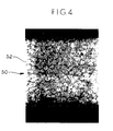
- FIG. 4 is a cut-away view of a solidified cable of the present invention enlarged fifty times wherein the cable 50 includes fibers 52 which are closely compacted.
- the use of the solidification to terminate the end portion of the cable 50 reduces the gaps 43 and voids 45 which occurred in the prior art (FIG. 3).
- This solidified cable may be attached to a substrate via brazing, bolting, ultrasonic welding or soldering.
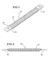
- a braided cable 60 having solidified ends 61, 62 includes an oxidation bump 70.
- the cable 60 has a maximum voltage drop of 2.5 mV when a current of 205 amps is passed and measured after thermal stabilization.
- Each solidified end 61,62 may withstand a pull force of 485 pounds and may be waterproof.
- the method of forming the cable having an oxidation bump 70 includes the steps of:
- the U-shaped bump 70 is formed to extend the cable 60 in a direction beyond the plane of the ends 61,62 of the cable 60.
- the bump in then oxidized by the application of two prongs to the sides of said bump and heating said bump to a specified temperature.
- Voltage drop measurements shall not exceed 5 millivolts, when measured in accordance with MIL-T-13513B(AT) (Military Specification, U.S. Army Tank-Automotive Command), paragraph 4.6.3.
- Procedure The samples were connected into a circuit adjusted to pass a current of 205 amps. The millivolt drop was measured from the edge of the termination to a point on the braided cable 6 ⁇ 35 mm (1/4 inch) inward. The voltage drop and test current values were recorded. This was done in the as received condition (cold) and after the assembly had thermally stabilized.
- Initial Voltage Drop Sample Number Direct Current (amperes) Voltage Max Voltage Max.
- Samples 1-3 are cables having solidified ends.
- Samples 4-6 are cables having ferrule crimps. Results: When the samples were tested at a test current of 205 amps and measured after thermal stabilization, they were all observed to meet the requirements of MIL-T-13513B(AT), i.e. a voltage drop of less than 5 millivolts. It was observed that the solidified end samples exhibited a lower voltage drop result than the cable having ferrule crimps.
- the temperature of the termination shall not exceed by more than 5°C (9°F) the temperature of the braid material, when tested as specified in MIL-T-13513B(AT), paragraph 4.6.4.
- Procedure The assemblies were connected into a test circuit adjusted to pass 205 amps of current. The current was maintained until the temperature of the terminated ends and the splice stabilized. These stabilized temperature values were recorded. The temperature was recorded by means of a thermocouple embedded in the terminated end and also in the braided material. All results are recorded in Table 2. Current Rating Sample No. Direct Current (amperes) Temp.
- Samples 4-6 are cables having ferrule crimps. Results : All of the assemblies met the requirements of MIL-T-13513B(AT), there were no significant differences between the solidified ends vs. ferrule crimps, as far as the results of this test were concerned.
- the terminated end (solidified end or ferrule crimp) temperature shall not exceed by more than 18°F the temperature of the attached braid, when tested as specified in MIL-T-13513B(AT), paragraph 4.6.5.
- the subsequent post-test voltage drop measurements shall meet the requirements specified in Table I of MIL-T-13513B(AT), and shall be less than 8 millivolts.
- Procedure The samples were connected into a circuit so that 256 amps could pass through them. The stabilized temperatures of the terminated ends (solidified end and ferrule crimp) and the braid material were recorded. Then, the samples were allowed to return to room temperature. Then, a test current of 410 amps was allowed to pass through the samples for a period of five minutes.
- Samples 1-3 are cables having solidified ends. Samples 4-6 are cables having ferrule crimps. Current Overload - 200% Sample No. Direct Current (amperes) Temp. °C (°F) Barrel Stranding Pass/Fail Barrel Stranding AT °C (°F) Max.
- Samples 1-3 are cables having solidified ends. Samples 4-6 are cables having ferrule crimps. Post-Overload Voltage Drop Sample Number Direct Current (amperes) Voltage Max.
- Samples 1-3 are cables having solidified ends. Samples 4-6 are cables having ferrule crimps.
- the terminated ends (solidified ends or ferrule crimps) shall withstand a minimum mechanical strength of 2158N (485 pounds) pull force without breaking or becoming distorted to the extent of being unfit for further use.
- the samples shall be tested in accordance with MIL-T-13513B(AT), paragraph 4.6.6.
- Procedure The test specimens were placed in a standard tensile testing machine and a sufficient force was applied to pull the cable to its minimum force rating of 485 pounds. The condition of the assembly was examined following the application of this minimum force requirement. Testing was performed at room temperature, and the speed of the test machine was 4 inches per minute. Two of the three samples of each type were tested by placing both ends of the sample in the grips of the universal test machine.
- the sample shall show no evidence of mechanical or electrical failure, when tested in accordance with MIL-T-13513B (AT), paragraph 4.6.7.1, vibration. Following the vibration test, the samples shall meet the mechanical strength test requirements.
- Procedure One end of each sample was mounted on a vibration table with the other end of the sample secured to a stable support. The sample was vibrated for one hour in each of three mutually perpendicular axes at an amplitude of .060 inches and a frequency of 10 to 55 to 10 Hz, with the frequency range accomplished once each minute. Following vibration testing, the samples were - subjected to the mechanical strength test requirements defined earlier in this report, except that the samples were pulled to failure. Test to Failure After Sine Vibration Sample No.
- the samples shall be checked for their ability to withstand a bolt being torqued onto them.
- a pre-drilled hole in the sample shall be placed over a tapped hole in an aluminum block, and a bolt shall be threaded through the sample into the block.
- the bolt shall be torqued to a torque of 11 ⁇ 3 joules (100 inch pounds).
- the sample shall be tested with and without washers. After each torque test, the samples shall be visually inspected for any evidence of degradation.
- Procedure The samples were tested as outlined in the requirements section above, and all observations are recorded in Table 6.
- One solidified end assembly and one ferrule crimp assembly shall be microsectioned using standard metallographic techniques. Samples shall be placed in an acrylic mounting compound, ground, and polished. The samples shall then be visually inspected for any evidence of voiding at the termination area (solidified end or ferrule crimp). Photographs of the microsections shall be taken. Results: The solidified crimp exhibited very little voiding in the termination area, whereas the ferrule crimp assembly did have voiding in this area. Micrographs are submitted with this application.
Landscapes
- Engineering & Computer Science (AREA)
- Manufacturing & Machinery (AREA)
- Connections Effected By Soldering, Adhesion, Or Permanent Deformation (AREA)
Claims (11)
- Flexibles stromführendes Flechtkabel, wobei das Kabel einen Endabschnitt (61) aufweist, welcher mittels einer Punkt-Schweißvorrichtung verfestigt ist, wobei benachbart dem Endabschnitt ein U-förmiger oxidierter Höcker (70) ausgebildet ist, der sich in einer Richtung über die Ebene der Enden (61, 62) des Kabels hinaus erstreckt.
- Flechtkabel nach Anspruch 1, bei welchem das Kabel einen maximalen Spannungsabfall von 2,5 mV aufweist, wenn ein Strom von 205 A (amps) geführt wird, und zwar gemessen nach thermischer Stabilisierung.
- Flechtkabel nach Anspruch 1, bei welchem das verfestigte Ende einer Zugkraft von 2158 N (485 Pfund) widerstehen wird.
- Flechtkabel nach Anspruch 1, bei welchem das Kabel an beiden Enden (61, 62) verfestigt ist.
- Flechtkabel nach Anspruch 1, bei welchem der oxidierte Höcker (70) eine U-förmige Einkerbung des Kabels darstellt.
- Flechtkabel nach Anspruch 1, bei welchem der Endabschnitt (61) zu einem einstückigen Glied komprimiert ist, wobei Ausspanungen bzw. Hohlräume reduziert sind und die Befestigung des Endabschnittes an einer stromführenden Vorrichtung ermöglicht ist.
- Flechtkabel nach Anspruch 1, bei welchem der Endabschnitt (61) wasserdicht bzw. wasserfest ist.
- Verfahren zur Herstellung eines Flechtkabels mit einem verfestigten Ende (61), umfassend die Schritte:Einführen eines Endabschnittes (61) eines Kabels in eine PunktSchweißvorrichtung;Verfestigen des Endabschnittes (61) des Kabels mittels der Punkt-Schweißvorrichtung bei 593°C bis 1093°C (1100°F bis 2000°F) bei 6,9 . 104 bis 6,9 . 105 Pa (10 bis 100 psi);Bilden eines U-förmigen Höckers (70) an dem Kabel; undOxidieren des Höckers.
- Verfahren nach Anspruch 8, bei welchem die Punkt-Schweißvorrichtung über eine Thermo-Rückkopplungs-Steuereinheit bzw. eine Thermoregeleinheit kalibriert ist.
- Verfahren nach Anspruch 8, bei welchem der Endabschnitt 61 mittels einer speziell angepaßten Spitze der Punkt-Schweißvorrichtung verfestigt ist bzw. wird.
- Verfahren nach Anspruch 8, bei welchem die Oxidation des Höcken veranlaßt wird durch Anwendung von zwei Zinken an den Seiten des Höckers und Erwärmen des Höckers auf eine spezifische Temperatur.
Applications Claiming Priority (2)
| Application Number | Priority Date | Filing Date | Title |
|---|---|---|---|
| US08/307,945 US5541380A (en) | 1994-09-16 | 1994-09-16 | Braided cable solidification |
| US307945 | 1994-09-16 |
Publications (3)
| Publication Number | Publication Date |
|---|---|
| EP0707321A2 EP0707321A2 (de) | 1996-04-17 |
| EP0707321A3 EP0707321A3 (de) | 1996-09-18 |
| EP0707321B1 true EP0707321B1 (de) | 2000-01-26 |
Family
ID=23191842
Family Applications (1)
| Application Number | Title | Priority Date | Filing Date |
|---|---|---|---|
| EP95306490A Expired - Lifetime EP0707321B1 (de) | 1994-09-16 | 1995-09-14 | Litzenleiter mit verfestigtem Ende |
Country Status (3)
| Country | Link |
|---|---|
| US (1) | US5541380A (de) |
| EP (1) | EP0707321B1 (de) |
| DE (1) | DE69514750T2 (de) |
Families Citing this family (42)
| Publication number | Priority date | Publication date | Assignee | Title |
|---|---|---|---|---|
| USD400169S (en) | 1995-09-27 | 1998-10-27 | Sony Corporation | Leading wire |
| US5948175A (en) * | 1996-12-12 | 1999-09-07 | Hughes Electronics Corporation | Strap device clamping soldered wires for use in solar cell arrays |
| DE19741144C1 (de) * | 1997-09-18 | 1999-04-15 | Siemens Matsushita Components | Stromübertragungselement |
| DE19906088A1 (de) * | 1998-08-01 | 2000-02-03 | Welcker F | Batteriepolanschlußkabel |
| ES2152166B1 (es) * | 1998-10-06 | 2001-08-01 | Casa Masfarne S A | Cable conductor electrico |
| GB0705313D0 (en) * | 2007-03-20 | 2007-04-25 | Yazaki Europe Ltd | Connector |
| DE102007045512A1 (de) * | 2007-09-24 | 2009-04-09 | Continental Automotive Gmbh | Kabel, Anordnung mit dem Kabel und Kabelherstellverfahren sowie Vorrichtung zur Herstellung des Kabels |
| EP2441103B2 (de) * | 2009-06-08 | 2018-09-12 | Auto-Kabel Management GmbH | Batteriezellenverbinder |
| DE102011077691A1 (de) * | 2011-06-17 | 2012-12-20 | Robert Bosch Gmbh | Verbinder für elektrische Anschlüsse und Verfahren zum Verbinden von elektrischen Bauteilen |
| DE102012004532A1 (de) * | 2012-03-06 | 2013-09-12 | Audi Ag | Batterie, insbesondere für ein Fahrzeug, und Verfahren zum Fertigen einer Batterie |
| JP2014022141A (ja) * | 2012-07-17 | 2014-02-03 | Auto Network Gijutsu Kenkyusho:Kk | 電気接続部材及び電気接続部材の製造方法 |
| US9561064B2 (en) | 2012-11-21 | 2017-02-07 | Pioneer Surgical Technology, Inc. | Bone plate system and method |
| US10765465B2 (en) | 2012-11-21 | 2020-09-08 | A&E Advanced Closure Systems, Llc | Tensioning instrument |
| DE102013202513B4 (de) | 2013-02-15 | 2023-04-27 | Te Connectivity Germany Gmbh | Elektrischer Verbinder |
| DE102013004708A1 (de) * | 2013-03-19 | 2014-09-25 | Amphenol-Tuchel Electronics Gmbh | Elektrischer Litzenleiter mit Rundsteckkontaktbuchse |
| JP6032558B2 (ja) * | 2013-09-17 | 2016-11-30 | 住友電装株式会社 | 端子金具付き導体 |
| US9999454B2 (en) | 2013-12-05 | 2018-06-19 | A&E Advanced Closure Systems, Llc | Bone plate system and method |
| US10314635B2 (en) | 2014-05-28 | 2019-06-11 | A&E Advanced Closure Systems, Llc | Tensioning instruments |
| DE102014109173B4 (de) * | 2014-07-01 | 2023-06-07 | Te Connectivity Germany Gmbh | Elektrische Kontakteinrichtung und elektrische Schweißverbindung sowie Verfahren zum Herstellen einer Kontakteinrichtung und zum Einrichten einer Schweißverbindung |
| CN107430908B (zh) * | 2015-04-21 | 2020-03-10 | 住友电装株式会社 | 导电部件 |
| CN104868340B (zh) * | 2015-04-22 | 2015-12-09 | 山东达驰阿尔发电气有限公司 | 电气设备连接用铜编织带的制作方法 |
| JP6409672B2 (ja) * | 2015-05-14 | 2018-10-24 | 株式会社オートネットワーク技術研究所 | 電線モジュール |
| DE102015219304B4 (de) * | 2015-10-06 | 2024-05-23 | Te Connectivity Germany Gmbh | Kontaktelement aus Flechtdraht und Verfahren zur Herstellung eines Kontaktelements |
| DE102015118443A1 (de) * | 2015-10-28 | 2017-05-04 | Eugen Forschner Gmbh | Vorrichtung zum Verbinden von elektrischen Bauteilen mit einer Stromversorgung |
| JP6528652B2 (ja) * | 2015-11-12 | 2019-06-12 | 住友電装株式会社 | 導電部材及び端子付導電部材 |
| JP6582903B2 (ja) * | 2015-11-12 | 2019-10-02 | 住友電装株式会社 | 導電部材及び導電部材の製造方法 |
| US11497538B2 (en) | 2016-01-22 | 2022-11-15 | Fort Wayne Metals Research Products, Llc | Woven or braided tubular metal construct |
| CA3012198C (en) | 2016-01-22 | 2022-10-04 | A&E Advanced Closure Systems, Llc | Bone plate having a connector and a connector for a surgical loop |
| WO2018022283A1 (en) | 2016-07-29 | 2018-02-01 | Pioneer Surgical Technology, Inc. | Surgical cable tensioner |
| US11107602B2 (en) | 2016-11-08 | 2021-08-31 | Autonetworks Technologies, Ltd. | Electric wire conductor, covered electric wire, and wiring harness |
| JP6741215B2 (ja) * | 2017-01-20 | 2020-08-19 | 株式会社オートネットワーク技術研究所 | 接続モジュール |
| DE102017112947A1 (de) * | 2017-06-13 | 2018-12-13 | Te Connectivity Germany Gmbh | Elektrischer Hochstromverbinder sowie Verfahren zum Herstellen eines elektrischen Hochstromverbinders |
| DE102017221148A1 (de) * | 2017-11-27 | 2019-05-29 | Leoni Kabel Gmbh | Hochstromverbinder sowie Vorrichtung und Verfahren zum Herstellen eines Hochstromverbinders zum Verbinden von Batteriemodulen |
| DE112020000459T5 (de) | 2019-01-21 | 2021-11-25 | Royal Precision Products, Llc | Stromverteilungsanordnung mit schraubenlosem sammelschienensystem |
| US11145434B2 (en) * | 2019-05-08 | 2021-10-12 | Erico International Corporation | Low voltage power conductor and system |
| US11488742B2 (en) * | 2019-09-09 | 2022-11-01 | Eaton Intelligent Power Limited | Electrical busbar and method of fabricating the same |
| CN116325383A (zh) | 2020-10-08 | 2023-06-23 | 怡得乐工业有限公司 | 汇流条连接器 |
| DE102021109369A1 (de) * | 2021-04-14 | 2022-10-20 | Te Connectivity Germany Gmbh | Elektrische Leiteranordnung, Verfahren zur Herstellung einer elektrischen Leiteranordnung |
| JP7582048B2 (ja) * | 2021-04-27 | 2024-11-13 | 住友電装株式会社 | 導電性接続部材 |
| US12136500B2 (en) | 2021-08-18 | 2024-11-05 | Eaton Intelligent Power Limited | Electrical busbar and method of fabricating the same |
| US20250279223A1 (en) * | 2024-02-29 | 2025-09-04 | Fca Us Llc | High voltage cable integrated end connector system that eliminates terminal |
| US20250279594A1 (en) * | 2024-02-29 | 2025-09-04 | Fca Us Llc | High voltage cable integrated end connector system that eliminates terminal |
Family Cites Families (6)
| Publication number | Priority date | Publication date | Assignee | Title |
|---|---|---|---|---|
| US994818A (en) | 1909-06-23 | 1911-06-13 | Electric Railway Improvement | Rail-bond. |
| DE419005C (de) * | 1924-06-25 | 1925-09-18 | Cie Lorraine De Charbons | Anschlussstueck fuer biegsame metallene Kabel |
| GB1052468A (de) * | 1963-12-27 | |||
| US4922072A (en) * | 1988-06-22 | 1990-05-01 | Methode Electronics, Inc. | Wire connecting method |
| FR2636179B1 (fr) * | 1988-09-02 | 1990-09-07 | Mitnikoff Michel | Procede de realisation de mise en forme de raccordement d'une tresse et produit ainsi obtenu |
| US5155326A (en) * | 1990-12-24 | 1992-10-13 | United Technologies Corporation | Porous materials brazing |
-
1994
- 1994-09-16 US US08/307,945 patent/US5541380A/en not_active Expired - Lifetime
-
1995
- 1995-09-14 DE DE69514750T patent/DE69514750T2/de not_active Expired - Fee Related
- 1995-09-14 EP EP95306490A patent/EP0707321B1/de not_active Expired - Lifetime
Also Published As
| Publication number | Publication date |
|---|---|
| EP0707321A2 (de) | 1996-04-17 |
| EP0707321A3 (de) | 1996-09-18 |
| DE69514750T2 (de) | 2000-06-15 |
| US5541380A (en) | 1996-07-30 |
| DE69514750D1 (de) | 2000-03-02 |
Similar Documents
| Publication | Publication Date | Title |
|---|---|---|
| EP0707321B1 (de) | Litzenleiter mit verfestigtem Ende | |
| EP0225043B1 (de) | Kabelverbindung | |
| US5290638A (en) | Superconducting joint with niobium-tin | |
| US5877472A (en) | System for laser-welding components of an implantable device | |
| US6452101B1 (en) | Multi-core conductive wire and a method of manufacturing the same | |
| EP3304649B1 (de) | Verfahren zum verbinden eines leiters mit einem basismetall an einem anschlusselement mit kupfer durch schweissen | |
| US20140262501A1 (en) | Durable copper to aluminum welded connection | |
| US4902867A (en) | Method of joining an insulated wire to a conductive terminal | |
| JPH05114450A (ja) | 絶縁被覆導線の接合方法及び接合体 | |
| US4056880A (en) | Method for connecting dynamoelectric machine coils | |
| DE102011011409B4 (de) | Anschlussteil und Verbindung für elektrische Anlagen | |
| US5126527A (en) | High temperature solder device for flat cables | |
| US4917623A (en) | Terminator of a multi-strand electrical conductor | |
| CA1224855A (en) | Connectors for power distribution cables | |
| JP2644860B2 (ja) | 圧接用接合端子 | |
| GB2057781A (en) | Electrical connector assemblies | |
| US4710080A (en) | Clamping apparatus for making an improved electrical connection | |
| US4644625A (en) | Plier tool for making an improved electrical connection | |
| JPH0982447A (ja) | 電線接続方法 | |
| US4151392A (en) | Method of manufacturing electrical connector | |
| US4482782A (en) | Method of providing a soldered electrical connection and the electrical connection | |
| DE102010053768B4 (de) | Verfahren zum Verbinden eines Aluminiumkabels mit einem Anschlussteil | |
| JPH0982377A (ja) | 電線接続方法 | |
| JP3494052B2 (ja) | 絶縁被覆線端子 | |
| JPH11283683A (ja) | 多芯導体部材とその製造法及びそれを用いた各種用途とその製造法 |
Legal Events
| Date | Code | Title | Description |
|---|---|---|---|
| PUAI | Public reference made under article 153(3) epc to a published international application that has entered the european phase |
Free format text: ORIGINAL CODE: 0009012 |
|
| AK | Designated contracting states |
Kind code of ref document: A2 Designated state(s): DE FR GB IT |
|
| PUAL | Search report despatched |
Free format text: ORIGINAL CODE: 0009013 |
|
| RHK1 | Main classification (correction) |
Ipc: H01B 5/00 |
|
| AK | Designated contracting states |
Kind code of ref document: A3 Designated state(s): DE FR GB IT |
|
| 17P | Request for examination filed |
Effective date: 19970303 |
|
| 17Q | First examination report despatched |
Effective date: 19980128 |
|
| GRAG | Despatch of communication of intention to grant |
Free format text: ORIGINAL CODE: EPIDOS AGRA |
|
| GRAG | Despatch of communication of intention to grant |
Free format text: ORIGINAL CODE: EPIDOS AGRA |
|
| GRAH | Despatch of communication of intention to grant a patent |
Free format text: ORIGINAL CODE: EPIDOS IGRA |
|
| GRAH | Despatch of communication of intention to grant a patent |
Free format text: ORIGINAL CODE: EPIDOS IGRA |
|
| GRAA | (expected) grant |
Free format text: ORIGINAL CODE: 0009210 |
|
| AK | Designated contracting states |
Kind code of ref document: B1 Designated state(s): DE FR GB IT |
|
| REF | Corresponds to: |
Ref document number: 69514750 Country of ref document: DE Date of ref document: 20000302 |
|
| ITF | It: translation for a ep patent filed | ||
| ET | Fr: translation filed | ||
| PLBE | No opposition filed within time limit |
Free format text: ORIGINAL CODE: 0009261 |
|
| STAA | Information on the status of an ep patent application or granted ep patent |
Free format text: STATUS: NO OPPOSITION FILED WITHIN TIME LIMIT |
|
| 26N | No opposition filed | ||
| PGFP | Annual fee paid to national office [announced via postgrant information from national office to epo] |
Ref country code: FR Payment date: 20010817 Year of fee payment: 7 |
|
| PGFP | Annual fee paid to national office [announced via postgrant information from national office to epo] |
Ref country code: DE Payment date: 20010820 Year of fee payment: 7 |
|
| PGFP | Annual fee paid to national office [announced via postgrant information from national office to epo] |
Ref country code: GB Payment date: 20010821 Year of fee payment: 7 |
|
| REG | Reference to a national code |
Ref country code: GB Ref legal event code: IF02 |
|
| PG25 | Lapsed in a contracting state [announced via postgrant information from national office to epo] |
Ref country code: GB Free format text: LAPSE BECAUSE OF NON-PAYMENT OF DUE FEES Effective date: 20020914 |
|
| PG25 | Lapsed in a contracting state [announced via postgrant information from national office to epo] |
Ref country code: DE Free format text: LAPSE BECAUSE OF NON-PAYMENT OF DUE FEES Effective date: 20030401 |
|
| GBPC | Gb: european patent ceased through non-payment of renewal fee |
Effective date: 20020914 |
|
| PG25 | Lapsed in a contracting state [announced via postgrant information from national office to epo] |
Ref country code: FR Free format text: LAPSE BECAUSE OF NON-PAYMENT OF DUE FEES Effective date: 20030603 |
|
| REG | Reference to a national code |
Ref country code: FR Ref legal event code: ST |
|
| PG25 | Lapsed in a contracting state [announced via postgrant information from national office to epo] |
Ref country code: IT Free format text: LAPSE BECAUSE OF NON-PAYMENT OF DUE FEES Effective date: 20050914 |