EP0707329B1 - Interrupteur de sécurité - Google Patents
Interrupteur de sécurité Download PDFInfo
- Publication number
- EP0707329B1 EP0707329B1 EP95111312A EP95111312A EP0707329B1 EP 0707329 B1 EP0707329 B1 EP 0707329B1 EP 95111312 A EP95111312 A EP 95111312A EP 95111312 A EP95111312 A EP 95111312A EP 0707329 B1 EP0707329 B1 EP 0707329B1
- Authority
- EP
- European Patent Office
- Prior art keywords
- housing
- locking
- safety switch
- switching
- axis
- Prior art date
- Legal status (The legal status is an assumption and is not a legal conclusion. Google has not performed a legal analysis and makes no representation as to the accuracy of the status listed.)
- Expired - Lifetime
Links
- 230000002093 peripheral effect Effects 0.000 claims description 8
- 238000006073 displacement reaction Methods 0.000 claims description 3
- 238000013459 approach Methods 0.000 description 23
- 230000007246 mechanism Effects 0.000 description 12
- 238000010276 construction Methods 0.000 description 2
- 238000013461 design Methods 0.000 description 2
- 230000006872 improvement Effects 0.000 description 2
- 238000000034 method Methods 0.000 description 2
- 230000008569 process Effects 0.000 description 2
- 230000004913 activation Effects 0.000 description 1
- 230000000903 blocking effect Effects 0.000 description 1
- 238000011109 contamination Methods 0.000 description 1
- 230000000694 effects Effects 0.000 description 1
- 238000003780 insertion Methods 0.000 description 1
- 230000037431 insertion Effects 0.000 description 1
- 230000003993 interaction Effects 0.000 description 1
- 238000004519 manufacturing process Methods 0.000 description 1
- 230000001681 protective effect Effects 0.000 description 1
- 238000012546 transfer Methods 0.000 description 1
Images


Classifications
-
- F—MECHANICAL ENGINEERING; LIGHTING; HEATING; WEAPONS; BLASTING
- F16—ENGINEERING ELEMENTS AND UNITS; GENERAL MEASURES FOR PRODUCING AND MAINTAINING EFFECTIVE FUNCTIONING OF MACHINES OR INSTALLATIONS; THERMAL INSULATION IN GENERAL
- F16P—SAFETY DEVICES IN GENERAL; SAFETY DEVICES FOR PRESSES
- F16P3/00—Safety devices acting in conjunction with the control or operation of a machine; Control arrangements requiring the simultaneous use of two or more parts of the body
- F16P3/08—Safety devices acting in conjunction with the control or operation of a machine; Control arrangements requiring the simultaneous use of two or more parts of the body in connection with the locking of doors, covers, guards, or like members giving access to moving machine parts
-
- H—ELECTRICITY
- H01—ELECTRIC ELEMENTS
- H01H—ELECTRIC SWITCHES; RELAYS; SELECTORS; EMERGENCY PROTECTIVE DEVICES
- H01H27/00—Switches operated by a removable member, e.g. key, plug or plate; Switches operated by setting members according to a single predetermined combination out of several possible settings
- H01H27/002—Switches operated by a removable member, e.g. key, plug or plate; Switches operated by setting members according to a single predetermined combination out of several possible settings wherein one single insertion movement of a key comprises an unlocking stroke and a switch actuating stroke, e.g. security switch for safety guards
- H01H2027/005—Switches operated by a removable member, e.g. key, plug or plate; Switches operated by setting members according to a single predetermined combination out of several possible settings wherein one single insertion movement of a key comprises an unlocking stroke and a switch actuating stroke, e.g. security switch for safety guards the key receiving part having multiple openings to allow keys from different directions to operate the switch
Definitions
- the invention relates to a safety switch with a housing, in which a contact-bearing switching plunger can be moved back and forth is supported by a rotatably mounted ratchet can be operated, which in turn is adapted by an operator Shape in the sense of the switch operation is rotatable for Approach openings are provided in the housing on two sides, whereby the ratchet wheel in the sense of locking its rotary motion spring devices on both sides are assigned to the adapted actuator against the spring force are movable into a position releasing the ratchet.
- Such safety switches are used for forced shutdown the power supply, for example if a protective cover by one Device, a machine or the like is removed, cabinet doors be opened and the like. It exists in the sense of Security function the requirement, if possible take care to ensure that unauthorized or fundamentally authorized persons do not become with the help of simply simulated actuators the switch in the sense can activate its activation. Since the manufacturer in such Safety switches are not fixed in advance, in what position such a safety switch for the user is attached, with regard to appropriate user-friendliness in connection with keeping the number of types low such safety switch also the desire to design it in such a way that they are from two different sides, for example can be approached by the actuator.
- the ratchet wheel is essentially divided several times.
- a middle part acts with the plunger carrying the contacts together, while laterally provided ratchet parts by a Actuator through openings on two different sides of the housing can retract, parallel to the axis of rotation of the ratchet against the Force can be shifted from return springs, causing lugs on the tappet, which has locking surfaces on these relocatable ratchet parts cooperate with these blocking areas out of engagement devices.
- the ratchet is from a middle position when using one approach opening in one direction of rotation, when using the other approach opening in the other direction of rotation, each in the sense of the switch actuation, rotatable.
- Manipulation security can only be seen in two dimensions, since one for example, the two locking elements with two screwdrivers can operate and with appropriate insertion still There is still room to operate the ratchet. Despite the complicated Protection against manipulation is therefore also here in need of improvement.
- the present invention has for its object a safety switch to create the generic type, in which the Possibility of choosing one of different approach directions and a very high security against manipulation with a simple, space-saving constructive structure can be achieved.
- the solution according to the invention consists of a generic one Safety switch in that in the switching wheel, rotatable with this, a locking piece essentially radially on each of its sides is arranged movable to the ratchet wheel axis, the two locking pieces 2, each assigned to one of the approach openings, with the adapted one Acting actuator interacting in the sense of radial displacement Have sections and the two locking pieces each one Have locking section that with a corresponding locking trained section of the housing or for it ratchet axle arranged in a rotationally fixed manner in the housing interacts.
- the two locking pieces integrated in the ratchet have only one low degree of freedom.
- the overall arrangement builds extraordinarily compact and space-saving, as the locking pieces are on the side of the ratchet are arranged. There are also only two bars in total needed.
- the displaceability radially to the ratchet axis in the Side surfaces of the ratchet wheel act on the compact and narrow Construction of the switch with.
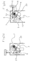
- the mechanism mentioned includes a ratchet 3, which on a Axis 4 is rotatably mounted, which in turn in adjacent Areas of a housing section 5 arranged fixed and non-rotatable is.
- the ratchet 3 has two in the illustrated embodiment radial grooves 6 offset from one another by 90 °, into each of which, depending on the direction of approach, an element of the still to be described Actuator 2 in the sense of the rotation of the ratchet wheel 3 from one Starting position can intervene in a switching end position, so far this twist is locked in a manner to be described.
- Said housing section 5 is expediently designed as a hood, which affects the entire switching and locking mechanism here records.
- the housing hood 5 is not with here Switch housing shown otherwise by a snap connection snap-together can be put together.
- the housing hood 5 has shown in the Exemplary embodiment on a side surface as well as on the top each a launch opening 7 for the adapted Actuator 2. Since the housing hood 5 the entire switching and Locking mechanism picks up, it is easily with this Mechanism can be moved 180 ° in two positions with the switch housing otherwise lock, so that a total of four different Approach directions are available.
- the for a predetermined Application opening 7 not required in the housing hood 5 is expedient to avoid a risk of contamination by a closing piece tightly closed.
- each pivotable on a Bearing journal 10 is mounted in an application plane perpendicular to axis 4.
- the bearing pins 10 are located at a predetermined distance to the axis 4.
- the pivotable locking pieces 9 are shown in the Embodiment according to Figures 1 - 2d also from the axis 4 crosses.
- This zone of passage of axis 4 through the Bolt pieces 9 is designed as a locking section 11, the a circular passage for the axis in the middle 4 has, on which on both sides in the pivoting direction Connect locking pieces 4 locking grooves 12.
- the axis 4 points at least in the passage area through the locking pieces 9 locking trained sections. In the illustrated Embodiment is over the entire length with two each other opposite locking surfaces 13 provided.
- the locking pieces 9 are in their locking position to be described pressed by a spring 14 for which the locking pieces 9 have a receiving pocket 15.
- the other end of the Spring 14 is in a notch 16 in the 8 delimiting the recess Shoulder 17 of the ratchet 3 supported.
- the locking pieces are 9 essentially designed as a three-armed lever.
- the one lever arm is used for storage on the journal 10.
- Another lever arm carries a sloping surface section at its free end 18, which is then used and to interact with the Actuator 2 comes when it approaches the opening at the top 7 passes.
- the third lever arm also has at its free end a sloping surface section 19, which then from Actuator 2 is acted upon when this is due to the lateral Approach opening 7 occurs.
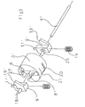
- the adapted actuator 2 which is complicated in its spatial form is in its interacting with the switching and locking mechanism
- the area is essentially bow-shaped and has on the one hand a cross piece 23 and also in the front area of it two bracket arms special switching pieces 24.
- the figure 2a illustrates that for both approach openings each for unlocking with the actuator 2 interacting surface sections 18 and 19 spatially offset to those with the crossbar 23 of the actuator 2 interacting radial grooves 6 of the ratchet wheel 3 lie, so that the unlocking only with the special additional switching pieces 24 are set in motion on the actuator 2 can.
- actuator 2 If actuator 2 is retracted from this position, the actuator 2 arrives with its contact pieces 24 the sloping surface sections 18 and 19 of the lever arms concerned the locking pieces 9 over and the crossbar 23 of the actuator 2 can in the radial groove 6 of the ratchet wheel 3 concerned enter and turn the ratchet wheel 3 if there is another entrainment, whereby after running over the cam 21, the end of Switch plunger 1 in the deep peripheral recess 22 in the outer jacket of the switching wheel 3 and thus the switching position of the switching plunger 1 is reached.
- the latter is for use in Figure 2c the lateral approach opening 7, in Figure 2d for use the upper approach opening 7 illustrated.
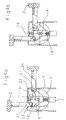
- 4a-d is again a switching wheel 3 'rotatable on an axis 4' circular Cross-section stored.
- the ratchet 3 ' also has radial grooves 6 and a small circumferential recess 20 with a control curve 21 merges into a deep peripheral recess 22.
- recesses 8 of the ratchet wheel 3 'locking pieces 9' are slidably guided, centrally a longitudinal slot 25 for the passage of the axis 4 ' to have.
- the recesses 8 ' are at one end as Pocket receptacle for the springs 14 formed.
- the latch pieces 9 ' each assigned to one of the approach openings 7, arm-like Ledges.
- the projection assigned to the lateral approach opening 7 contributes to interaction with the contact pieces at its free end 24 of the actuator 2 an inclined surface portion 19 ', while the projection assigned to the upper approach opening 7 is located in the surface section extending substantially perpendicular to the approach direction 18 '.
- the locking section 11 'of the locking pieces 9 ' is by a bolt protruding from one end formed for in the opposite area of the housing cover 5 'as a locking element interacting with it, a plug hole 26 is provided.
- the unlocking and switching process in this embodiment is as follows: In the locked starting position (FIG. 2a), the locking pieces 9 'are pressed by the springs 14 into a position in which the bolts 11' are inserted into the plug bores 26 in a locking manner. Since a section of the ratchet wheel 3 ' also has a through hole 27 for the bolts 11' on each side and furthermore, with regard to the guide surfaces for the locking pieces 9 'in the recesses 8', the ratchet wheel 3 'is also prevented from rotating.
- the actuator 2 now enters either the lower or the lateral approach opening 7, its switching pieces 24, when the upper approach opening 7 is selected, meet the surface section 18 'of the locking piece 9' lying transversely in the movement path, and when the lateral approach opening 7 is selected, the surface section 19 '.
- the locking pieces 9 ' are thereby pushed back against the force of the springs 14, whereby, guided in the recess 8', they in turn perform a movement radially to the axis 4 '.
- the bolt 11 ' comes out of the plug-in bore 26 of the housing hood 5', as a result of which the locking is released (FIG. 4b).
- the transverse web 23 also enters one of the radial grooves 6 of the switching wheel 3 '.
- the switching wheel 3 'together with the locking piece 9' can be rotated and thus the switching plunger 1 'can pass from the small peripheral recess 20 into the deep peripheral recess 22, so that the switching position is reached.
- the latter is illustrated for the use of the lateral approach opening 7 in FIG. 4c and for the use of the lower approach opening 7 in FIG. 4d.
- the housing hood 5 ' is 180 ° displaceably latched to the switch housing. Also at this embodiment, as illustrated in FIG the locked starting position, the surface sections 18 ', 19' spatially offset to the radial grooves 6 of the ratchet wheel 3 '.
Landscapes
- Engineering & Computer Science (AREA)
- General Engineering & Computer Science (AREA)
- Mechanical Engineering (AREA)
- Computer Security & Cryptography (AREA)
- Mechanisms For Operating Contacts (AREA)
- Push-Button Switches (AREA)
- Switch Cases, Indication, And Locking (AREA)
- Lock And Its Accessories (AREA)
Claims (10)
- Interrupteur de sécurité avec un boítier (5, 5'), dans lequel est monté avec un mouvement alternatif, un poussoir de commutation (1) faisant contact et pouvant être actionné par une roue de commande (3, 3') qui est montée à rotation et pivote à son tour par l'intermédiaire d'un actionneur (2) qui est réalisé selon une conception adaptée conformément à l'actionnement de l'interrupteur et pour lequel sont prévues dans le boítier (5, 5'), sur deux côtés, des ouvertures d'accès (7), dans lequel des dispositifs de verrouillage (9, 9') placés des deux côtés et fonctionnant sous l'action d'un ressort sont affectés à la roue de commande (3, 3') dans le sens de blocage de son mouvement de rotation et peuvent se déplacer avec l'actionneur adapté (2) à l'encontre de l'effet de ressort, dans une position libérant la roue de commande pour le mouvement de rotation, caractérisé en ce que, dans la roue de commande (3, 3'), un élément de verrou (9, 9') pivotant avec cette dernière sur chacun de ses côtés, est disposé de façon mobile sensiblement radialement à l'axe de la roue de commande (4, 4'), les deux éléments de verrou (9, 9') présentent deux tronçons de surface (18, 18' ; 19, 19') affectés respectivement à l'une des ouvertures d'accès (7) et coopérant avec l'actionneur (2) adapté, dans le sens de son déplacement radial et les deux éléments de verrou (9, 9') présentent respectivement un tronçon de verrouillage (11, 12 ; 11') qui coopère avec un tronçon (13 ; 26) du boítier (5') conçu pour verrouiller de manière correspondante ou avec l'axe de la roue de commande (4) disposé de manière fixe dans le boítier (5).
- Interrupteur de sécurité selon la revendication 1, caractérisé en ce que les tronçons de surface (18, 18' ; 19, 19') coopérant avec l'actionneur adapté (2, 23, 24) et faisant partie des éléments de verrouillage (9, 9') sont décalés en arrière vers les tronçons de surface coopérant avec l'actionneur, dans des rainures radiales (6) de la roue de commande (3, 3').
- Interrupteur de sécurité selon l'une des revendications précédentes, caractérisé en ce que la roue de commande (3, 3') est disposée avec ses éléments de verrouillage (9, 9') et son axe (4, 4') dans un tronçon de boítier réalisé comme enveloppe de boítier (5, 5') qui peut être assemblée avec le boítier de l'interrupteur en étant décalée par ailleurs respectivement de 180 °.
- Interrupteur de sécurité selon l'une des revendications précédentes, caractérisé en ce que, dans la partie centrale de la roue de commande (3, 3'), sur son enveloppe extérieure, une cavité périphérique (20) de profondeur réduite est formée pour le poussoir de commande (1) et une autre cavité périphérique (22) de profondeur nettement plus grande est prévue décalée de façon angulaire par rapport à cette dernière, les deux cavités périphériques étant assemblées l'une avec l'autre par l'intermédiaire d'une came de commande (21).
- Interrupteur de sécurité selon la revendication 2, caractérisé en ce que, pour la coopération avec les tronçons de surraces (18, 18' ; 19, 19') décalés en arrière et faisant partie des éléments de verrouillage (9, 9'), des éléments de commande (24) sont prévus sur l'actionneur (2) à son extrémité active, des deux côtés d'une tige transversale (23).
- Interrupteur de sécurité selon l'une des revendications précédentes, caractérisé en ce que l'ouverture d'accès (7) du boítier (5, 5') qui n'est pas respectivement nécessaire, a une fermeture étanche.
- Interrupteur de sécurité selon l'une des revendications précédentes, caractérisé en ce que les éléments de verrouillage (9) sont montés à rotation (sur 10) sur la roue de commande (3), à distance de la zone centrale de passage de l'axe (4) et ils présentent un tronçon de verrouillage (11) situé dans la zone de passage de l'axe (4) et comportant au moins, sur un côté d'un passage circulaire pour l'axe (4), une rainure de verrouillage (12) qui coopère avec les surfaces de verrouillage (13) formées sur l'axe (4).
- Interrupteur de sécurité selon l'une des revendications précédentes, caractérisé en ce que les éléments de verrouillage (9) sont réalisés sous la forme d'un levier à trois bras, l'un des bras servant au pivotement sur la roue de commande (3), les deux autres bras étant affectés respectivement à l'une des ouvertures d'accès (7) dans le boítier (5) et celles-ci présentant à leurs extrémités libres, des sections de surface (18, 19) obliques pour la coopération avec la tige transversale (23) de l'actionneur (2).
- Interrupteur de sécurité selon l'une des revendications 1 à 6, caractérisé en ce que les éléments de verrouillage (9') sont guidés radialement par rapport à l'axe (4') en se déplaçant dans des cavités (8'), des deux côtés de la roue de commande (3') et ils présentent comme section de verrouillage, un boulon (11') formant saillie qui, dans la position de verrouillage, s'engage dans un alésage (26) prévu dans la zone adjacente du boítier (5').
- Interrupteur de sécurité selon l'une des revendications 1 à 6 et 9, caractérisé en ce que les éléments de verrouillage (9') présentent deux éléments formant saillie affectés respectivement à l'une des ouvertures d'accès (7) et à l'extrémité libre desquelles sont formées des tronçons de surface (18', 19') coopérant avec la tige transversale (23) de l'actionneur (2).
Applications Claiming Priority (2)
| Application Number | Priority Date | Filing Date | Title |
|---|---|---|---|
| DE4436579A DE4436579C2 (de) | 1994-10-13 | 1994-10-13 | Sicherheitsschalter |
| DE4436579 | 1994-10-13 |
Publications (2)
| Publication Number | Publication Date |
|---|---|
| EP0707329A1 EP0707329A1 (fr) | 1996-04-17 |
| EP0707329B1 true EP0707329B1 (fr) | 2000-01-12 |
Family
ID=6530664
Family Applications (1)
| Application Number | Title | Priority Date | Filing Date |
|---|---|---|---|
| EP95111312A Expired - Lifetime EP0707329B1 (fr) | 1994-10-13 | 1995-07-19 | Interrupteur de sécurité |
Country Status (5)
| Country | Link |
|---|---|
| US (1) | US5622253A (fr) |
| EP (1) | EP0707329B1 (fr) |
| DE (2) | DE4436579C2 (fr) |
| DK (1) | DK0707329T3 (fr) |
| ES (1) | ES2140588T3 (fr) |
Families Citing this family (22)
| Publication number | Priority date | Publication date | Assignee | Title |
|---|---|---|---|---|
| DE29516230U1 (de) * | 1995-10-13 | 1995-12-07 | Hans Bernstein, Spezialfabrik für Schaltkontakte GmbH & Co, 32457 Porta Westfalica | Radiusbetätiger für Sicherheitsschalter |
| FR2741993B1 (fr) * | 1995-12-05 | 1998-01-16 | Schneider Electric Sa | Interrupteur electrique de securite a cle |
| DE29609012U1 (de) * | 1996-05-20 | 1996-10-24 | Hans Bernstein, Spezialfabrik für Schaltkontakte GmbH & Co, 32457 Porta Westfalica | Sicherheitsschalter |
| DE19649717A1 (de) * | 1996-11-30 | 1998-06-04 | Euchner Gmbh & Co | Sicherheitsschalter |
| US6118087A (en) | 1997-03-31 | 2000-09-12 | Idec Izumi Corporation | Safety switch |
| IT1292975B1 (it) † | 1997-04-11 | 1999-02-11 | Pizzato Elettrica Srl | Interruttore di sicurezza a chiave. |
| ITVI980017A1 (it) * | 1998-02-02 | 1999-08-02 | Pizzato Elettrica Srl | Interruttore elettrico di sicurezza |
| DE29803028U1 (de) * | 1998-02-20 | 1998-04-09 | Hans Bernstein Spezialfabrik für Schaltkontakte GmbH & Co, 32457 Porta Westfalica | Sicherheitsschalter |
| US6037551A (en) * | 1998-02-26 | 2000-03-14 | Idec Izumi Corporation | Safety switch |
| JP2000106066A (ja) * | 1998-07-30 | 2000-04-11 | Omron Corp | キースイッチ |
| US6720508B2 (en) * | 2001-07-06 | 2004-04-13 | Omron Corporation | Door switches |
| GB0214205D0 (en) * | 2002-06-19 | 2002-07-31 | Eja Ltd | Lockable switch mechanism |
| JP2006109206A (ja) * | 2004-10-07 | 2006-04-20 | Denso Corp | 筐体内の電池の活性・不活性を切り替えることのできる無線装置 |
| JP4522291B2 (ja) * | 2005-03-08 | 2010-08-11 | Idec株式会社 | 安全スイッチ |
| JP4673661B2 (ja) * | 2005-04-26 | 2011-04-20 | Idec株式会社 | 安全スイッチ |
| GB0519929D0 (en) * | 2005-09-30 | 2005-11-09 | Eja Ltd | Safety switch |
| JP4710648B2 (ja) * | 2006-02-23 | 2011-06-29 | オムロン株式会社 | 安全スイッチ |
| JP4747888B2 (ja) * | 2006-03-09 | 2011-08-17 | オムロン株式会社 | スイッチ |
| GB0700146D0 (en) * | 2007-01-05 | 2007-02-14 | Eja Ltd | Safety switch mounting |
| US20080223012A1 (en) * | 2007-03-13 | 2008-09-18 | Black & Decker, Inc. | Cordless electric mower fail-safe charge lockout |
| CN102426952A (zh) * | 2011-09-19 | 2012-04-25 | 广东天富电气集团有限公司 | 一种底板机械联锁装置及方法 |
| DE102016004835B4 (de) * | 2016-04-22 | 2022-12-22 | K.A. Schmersal Holding Gmbh & Co. Kg | Sicherheitsschalter |
Family Cites Families (13)
| Publication number | Priority date | Publication date | Assignee | Title |
|---|---|---|---|---|
| US3858018A (en) * | 1974-02-22 | 1974-12-31 | Gen Electric | Electrical switch with removable driving means |
| DE3100862C2 (de) * | 1981-01-14 | 1984-02-09 | K.A. Schmersal Gmbh & Co, 5600 Wuppertal | Sicherheitsschalter |
| DE3302631C2 (de) * | 1983-01-27 | 1985-02-07 | Hans & Jos. Kronenberg Gmbh, 5060 Bergisch Gladbach | Sicherheitsschalter mit Fehlschließsicherung |
| DE3330109C2 (de) * | 1983-08-20 | 1986-01-02 | K.A. Schmersal Gmbh & Co, 5600 Wuppertal | Elektrischer Schalter |
| US4963706A (en) * | 1989-01-12 | 1990-10-16 | Eja Engineering Company Limited | Safety switch assemblies |
| DE3943376C1 (fr) * | 1989-12-30 | 1991-06-20 | Kloeckner-Moeller Gmbh, 5300 Bonn, De | |
| ATE140339T1 (de) * | 1992-06-02 | 1996-07-15 | Eja Eng Plc | Schutzschalteinrichtungen |
| US5272279A (en) * | 1992-07-01 | 1993-12-21 | Bel Products Inc. | General purpose electrical box kit |
| KR100271225B1 (ko) * | 1992-08-31 | 2000-11-01 | 후나키 토시유키 | 안전스위치장치 |
| DE4303367C1 (de) * | 1993-02-05 | 1994-02-24 | Schmersal K A Gmbh & Co | Sicherheitsschalter |
| ES2110159T3 (es) * | 1993-09-21 | 1998-02-01 | Kronenberg Gmbh H & J | Interruptor de posicion. |
| DE4338910C1 (de) * | 1993-11-15 | 1995-02-16 | Bernstein Hans Spezialfabrik | Sicherheitsschalter |
| US5473127A (en) * | 1995-02-24 | 1995-12-05 | Honeywell Inc. | Interlock mechanism for a key operated door switch |
-
1994
- 1994-10-13 DE DE4436579A patent/DE4436579C2/de not_active Expired - Fee Related
-
1995
- 1995-07-19 DK DK95111312T patent/DK0707329T3/da active
- 1995-07-19 EP EP95111312A patent/EP0707329B1/fr not_active Expired - Lifetime
- 1995-07-19 ES ES95111312T patent/ES2140588T3/es not_active Expired - Lifetime
- 1995-07-19 DE DE59507601T patent/DE59507601D1/de not_active Expired - Fee Related
- 1995-10-02 US US08/537,475 patent/US5622253A/en not_active Expired - Lifetime
Also Published As
| Publication number | Publication date |
|---|---|
| DK0707329T3 (da) | 2000-06-26 |
| ES2140588T3 (es) | 2000-03-01 |
| DE59507601D1 (de) | 2000-02-17 |
| DE4436579C2 (de) | 1997-05-22 |
| EP0707329A1 (fr) | 1996-04-17 |
| US5622253A (en) | 1997-04-22 |
| DE4436579A1 (de) | 1996-04-25 |
Similar Documents
| Publication | Publication Date | Title |
|---|---|---|
| EP0707329B1 (fr) | Interrupteur de sécurité | |
| EP0653771B1 (fr) | Commutateur de sécurité | |
| DE69914429T2 (de) | Zylinderschloss-Schlüssel-Kombination | |
| DE3943376C1 (fr) | ||
| DE69407625T2 (de) | Sicherheitsschalter | |
| DE69614488T2 (de) | Sicherheitsschalter mit Schlüssel | |
| DE69932168T2 (de) | Schlüssel mit beweglichem element, schlüsselkopf und schloss | |
| EP1366503B1 (fr) | Interrupteur de securite a plaque de deblocage | |
| DE19632318A1 (de) | Verriegelungsvorrichtung für Schacht-Innendeckel | |
| DE69614587T2 (de) | Verriegelungsmechanismus für mit einem Schlüssel betätigbarer Schalter | |
| DE4321720C2 (de) | Verriegelungssystem | |
| EP0821124B1 (fr) | Serrure avec pêne montée dans une boíte de serrure dans laquelle elle coulisse transversalement | |
| CH630990A5 (de) | Permutationsschloss, insbesondere fuer taschen und koffern. | |
| EP1933345A1 (fr) | Système de verrouillage et de maneuvre d'un interrupteur pour générateur | |
| DE4039652C1 (en) | Detachable safety-interlock for electrical switch - has key guides chamfered to facilitate final engagement with coded cam | |
| DE3040586C2 (de) | Aufsetzschloß mit einer Schubfalle | |
| DE4407912C2 (de) | Elektromechanisches Schloß | |
| EP1295000B1 (fr) | Dispositif d'actionnement pour une serrure, notamment sur un vehicule | |
| DE19647631C2 (de) | Für einen Schutzhelm bestimmtes Steckschloß | |
| DE69703026T3 (de) | Schlüsselsicherheitsschalter | |
| DE69800457T2 (de) | Verschiebbarer Sicherheitsriegel | |
| EP3819422B1 (fr) | Articulation et séchoir à linge doté d'une telle articulation | |
| DE29910758U1 (de) | Einsteckschloß | |
| DE102016004835B4 (de) | Sicherheitsschalter | |
| DE3501297A1 (de) | Motorzentralverteilung |
Legal Events
| Date | Code | Title | Description |
|---|---|---|---|
| PUAI | Public reference made under article 153(3) epc to a published international application that has entered the european phase |
Free format text: ORIGINAL CODE: 0009012 |
|
| AK | Designated contracting states |
Kind code of ref document: A1 Designated state(s): BE CH DE DK ES FR GB IT LI NL SE |
|
| 17P | Request for examination filed |
Effective date: 19960607 |
|
| GRAG | Despatch of communication of intention to grant |
Free format text: ORIGINAL CODE: EPIDOS AGRA |
|
| GRAG | Despatch of communication of intention to grant |
Free format text: ORIGINAL CODE: EPIDOS AGRA |
|
| GRAH | Despatch of communication of intention to grant a patent |
Free format text: ORIGINAL CODE: EPIDOS IGRA |
|
| 17Q | First examination report despatched |
Effective date: 19990618 |
|
| GRAH | Despatch of communication of intention to grant a patent |
Free format text: ORIGINAL CODE: EPIDOS IGRA |
|
| ITF | It: translation for a ep patent filed | ||
| GRAA | (expected) grant |
Free format text: ORIGINAL CODE: 0009210 |
|
| AK | Designated contracting states |
Kind code of ref document: B1 Designated state(s): BE CH DE DK ES FR GB IT LI NL SE |
|
| REG | Reference to a national code |
Ref country code: CH Ref legal event code: NV Representative=s name: ISLER & PEDRAZZINI AG Ref country code: CH Ref legal event code: EP |
|
| REF | Corresponds to: |
Ref document number: 59507601 Country of ref document: DE Date of ref document: 20000217 |
|
| GBT | Gb: translation of ep patent filed (gb section 77(6)(a)/1977) |
Effective date: 20000128 |
|
| REG | Reference to a national code |
Ref country code: ES Ref legal event code: FG2A Ref document number: 2140588 Country of ref document: ES Kind code of ref document: T3 |
|
| ET | Fr: translation filed | ||
| REG | Reference to a national code |
Ref country code: DK Ref legal event code: T3 |
|
| PLBE | No opposition filed within time limit |
Free format text: ORIGINAL CODE: 0009261 |
|
| STAA | Information on the status of an ep patent application or granted ep patent |
Free format text: STATUS: NO OPPOSITION FILED WITHIN TIME LIMIT |
|
| 26N | No opposition filed | ||
| REG | Reference to a national code |
Ref country code: GB Ref legal event code: IF02 |
|
| PGFP | Annual fee paid to national office [announced via postgrant information from national office to epo] |
Ref country code: SE Payment date: 20030728 Year of fee payment: 9 Ref country code: ES Payment date: 20030728 Year of fee payment: 9 Ref country code: CH Payment date: 20030728 Year of fee payment: 9 |
|
| PGFP | Annual fee paid to national office [announced via postgrant information from national office to epo] |
Ref country code: BE Payment date: 20030729 Year of fee payment: 9 |
|
| PG25 | Lapsed in a contracting state [announced via postgrant information from national office to epo] |
Ref country code: SE Free format text: LAPSE BECAUSE OF NON-PAYMENT OF DUE FEES Effective date: 20040720 Ref country code: ES Free format text: LAPSE BECAUSE OF NON-PAYMENT OF DUE FEES Effective date: 20040720 |
|
| PG25 | Lapsed in a contracting state [announced via postgrant information from national office to epo] |
Ref country code: LI Free format text: LAPSE BECAUSE OF NON-PAYMENT OF DUE FEES Effective date: 20040731 Ref country code: CH Free format text: LAPSE BECAUSE OF NON-PAYMENT OF DUE FEES Effective date: 20040731 Ref country code: BE Free format text: LAPSE BECAUSE OF NON-PAYMENT OF DUE FEES Effective date: 20040731 |
|
| BERE | Be: lapsed |
Owner name: HANS *BERNSTEIN SPEZIALFABRIK FUR SCHALTKONTAKTE G Effective date: 20040731 |
|
| EUG | Se: european patent has lapsed | ||
| REG | Reference to a national code |
Ref country code: CH Ref legal event code: PL |
|
| REG | Reference to a national code |
Ref country code: ES Ref legal event code: FD2A Effective date: 20040720 |
|
| BERE | Be: lapsed |
Owner name: HANS *BERNSTEIN SPEZIALFABRIK FUR SCHALTKONTAKTE G Effective date: 20040731 |
|
| PGFP | Annual fee paid to national office [announced via postgrant information from national office to epo] |
Ref country code: DK Payment date: 20080722 Year of fee payment: 14 Ref country code: DE Payment date: 20080714 Year of fee payment: 14 |
|
| PGFP | Annual fee paid to national office [announced via postgrant information from national office to epo] |
Ref country code: NL Payment date: 20080722 Year of fee payment: 14 Ref country code: IT Payment date: 20080726 Year of fee payment: 14 Ref country code: FR Payment date: 20080718 Year of fee payment: 14 |
|
| PGFP | Annual fee paid to national office [announced via postgrant information from national office to epo] |
Ref country code: GB Payment date: 20080723 Year of fee payment: 14 |
|
| REG | Reference to a national code |
Ref country code: DK Ref legal event code: EBP |
|
| GBPC | Gb: european patent ceased through non-payment of renewal fee |
Effective date: 20090719 |
|
| NLV4 | Nl: lapsed or anulled due to non-payment of the annual fee |
Effective date: 20100201 |
|
| REG | Reference to a national code |
Ref country code: FR Ref legal event code: ST Effective date: 20100331 |
|
| PG25 | Lapsed in a contracting state [announced via postgrant information from national office to epo] |
Ref country code: FR Free format text: LAPSE BECAUSE OF NON-PAYMENT OF DUE FEES Effective date: 20090731 |
|
| PG25 | Lapsed in a contracting state [announced via postgrant information from national office to epo] |
Ref country code: GB Free format text: LAPSE BECAUSE OF NON-PAYMENT OF DUE FEES Effective date: 20090719 |
|
| PG25 | Lapsed in a contracting state [announced via postgrant information from national office to epo] |
Ref country code: DE Free format text: LAPSE BECAUSE OF NON-PAYMENT OF DUE FEES Effective date: 20100202 |
|
| PG25 | Lapsed in a contracting state [announced via postgrant information from national office to epo] |
Ref country code: DK Free format text: LAPSE BECAUSE OF NON-PAYMENT OF DUE FEES Effective date: 20090731 |
|
| PG25 | Lapsed in a contracting state [announced via postgrant information from national office to epo] |
Ref country code: IT Free format text: LAPSE BECAUSE OF NON-PAYMENT OF DUE FEES Effective date: 20090719 |
|
| PG25 | Lapsed in a contracting state [announced via postgrant information from national office to epo] |
Ref country code: NL Free format text: LAPSE BECAUSE OF NON-PAYMENT OF DUE FEES Effective date: 20100201 |