EP0707364B1 - Appareillage électrique à haute tension et à isolement gazeux équipé d'un dispositif court-circuiteur d'arc - Google Patents
Appareillage électrique à haute tension et à isolement gazeux équipé d'un dispositif court-circuiteur d'arc Download PDFInfo
- Publication number
- EP0707364B1 EP0707364B1 EP19950410093 EP95410093A EP0707364B1 EP 0707364 B1 EP0707364 B1 EP 0707364B1 EP 19950410093 EP19950410093 EP 19950410093 EP 95410093 A EP95410093 A EP 95410093A EP 0707364 B1 EP0707364 B1 EP 0707364B1
- Authority
- EP
- European Patent Office
- Prior art keywords
- contact means
- short
- switchgear apparatus
- electrical switchgear
- enclosure
- Prior art date
- Legal status (The legal status is an assumption and is not a legal conclusion. Google has not performed a legal analysis and makes no representation as to the accuracy of the status listed.)
- Expired - Lifetime
Links
- 230000007246 mechanism Effects 0.000 claims description 19
- 239000012528 membrane Substances 0.000 claims description 10
- SFZCNBIFKDRMGX-UHFFFAOYSA-N sulfur hexafluoride Chemical compound FS(F)(F)(F)(F)F SFZCNBIFKDRMGX-UHFFFAOYSA-N 0.000 claims description 8
- 239000004020 conductor Substances 0.000 claims description 7
- 230000005520 electrodynamics Effects 0.000 claims description 5
- 230000015572 biosynthetic process Effects 0.000 claims description 4
- 230000001154 acute effect Effects 0.000 claims description 3
- 230000006837 decompression Effects 0.000 claims description 3
- 230000005684 electric field Effects 0.000 claims description 3
- 238000009413 insulation Methods 0.000 claims description 3
- 239000000463 material Substances 0.000 claims description 3
- 229960000909 sulfur hexafluoride Drugs 0.000 claims description 3
- 238000004146 energy storage Methods 0.000 claims description 2
- 238000000926 separation method Methods 0.000 claims description 2
- 230000005405 multipole Effects 0.000 claims 1
- 229910018503 SF6 Inorganic materials 0.000 description 7
- 230000001960 triggered effect Effects 0.000 description 6
- 238000009825 accumulation Methods 0.000 description 5
- 239000003795 chemical substances by application Substances 0.000 description 2
- 230000006835 compression Effects 0.000 description 2
- 238000007906 compression Methods 0.000 description 2
- 210000000056 organ Anatomy 0.000 description 2
- 230000004224 protection Effects 0.000 description 2
- 239000007787 solid Substances 0.000 description 2
- RYGMFSIKBFXOCR-UHFFFAOYSA-N Copper Chemical compound [Cu] RYGMFSIKBFXOCR-UHFFFAOYSA-N 0.000 description 1
- 239000011248 coating agent Substances 0.000 description 1
- 238000000576 coating method Methods 0.000 description 1
- 229910052802 copper Inorganic materials 0.000 description 1
- 239000010949 copper Substances 0.000 description 1
- 238000010586 diagram Methods 0.000 description 1
- 230000000694 effects Effects 0.000 description 1
- 230000037431 insertion Effects 0.000 description 1
- 238000003780 insertion Methods 0.000 description 1
- 238000009434 installation Methods 0.000 description 1
- 238000010422 painting Methods 0.000 description 1
- 230000037452 priming Effects 0.000 description 1
- 230000000717 retained effect Effects 0.000 description 1
- 238000007789 sealing Methods 0.000 description 1
- 230000035939 shock Effects 0.000 description 1
- 238000009827 uniform distribution Methods 0.000 description 1
- 238000011144 upstream manufacturing Methods 0.000 description 1
Images


Classifications
-
- H—ELECTRICITY
- H02—GENERATION; CONVERSION OR DISTRIBUTION OF ELECTRIC POWER
- H02B—BOARDS, SUBSTATIONS OR SWITCHING ARRANGEMENTS FOR THE SUPPLY OR DISTRIBUTION OF ELECTRIC POWER
- H02B13/00—Arrangement of switchgear in which switches are enclosed in, or structurally associated with, a casing, e.g. cubicle
- H02B13/02—Arrangement of switchgear in which switches are enclosed in, or structurally associated with, a casing, e.g. cubicle with metal casing
- H02B13/035—Gas-insulated switchgear
- H02B13/065—Means for detecting or reacting to mechanical or electrical defects
-
- H—ELECTRICITY
- H02—GENERATION; CONVERSION OR DISTRIBUTION OF ELECTRIC POWER
- H02B—BOARDS, SUBSTATIONS OR SWITCHING ARRANGEMENTS FOR THE SUPPLY OR DISTRIBUTION OF ELECTRIC POWER
- H02B13/00—Arrangement of switchgear in which switches are enclosed in, or structurally associated with, a casing, e.g. cubicle
- H02B13/02—Arrangement of switchgear in which switches are enclosed in, or structurally associated with, a casing, e.g. cubicle with metal casing
- H02B13/035—Gas-insulated switchgear
- H02B13/075—Earthing arrangements
-
- H—ELECTRICITY
- H02—GENERATION; CONVERSION OR DISTRIBUTION OF ELECTRIC POWER
- H02B—BOARDS, SUBSTATIONS OR SWITCHING ARRANGEMENTS FOR THE SUPPLY OR DISTRIBUTION OF ELECTRIC POWER
- H02B13/00—Arrangement of switchgear in which switches are enclosed in, or structurally associated with, a casing, e.g. cubicle
- H02B13/02—Arrangement of switchgear in which switches are enclosed in, or structurally associated with, a casing, e.g. cubicle with metal casing
- H02B13/025—Safety arrangements, e.g. in case of excessive pressure or fire due to electrical defect
-
- H—ELECTRICITY
- H02—GENERATION; CONVERSION OR DISTRIBUTION OF ELECTRIC POWER
- H02B—BOARDS, SUBSTATIONS OR SWITCHING ARRANGEMENTS FOR THE SUPPLY OR DISTRIBUTION OF ELECTRIC POWER
- H02B13/00—Arrangement of switchgear in which switches are enclosed in, or structurally associated with, a casing, e.g. cubicle
- H02B13/02—Arrangement of switchgear in which switches are enclosed in, or structurally associated with, a casing, e.g. cubicle with metal casing
- H02B13/035—Gas-insulated switchgear
- H02B13/065—Means for detecting or reacting to mechanical or electrical defects
- H02B13/0655—Means for detecting or reacting to mechanical or electrical defects through monitoring changes of gas properties
Definitions
- the principle of such an arc short-circuiter consists in eliminating the internal arc by shunting it by a solid conductor path of low impedance constituting a short circuit between the phase conductors of electrical equipment.
- the document FR-A-2.687.022 relates to an armored device equipped with a disconnector automatic earthing system using three knife-shaped conductors mounted on a common rotary shaft.
- the trigger mechanism includes a piston pressure.
- the moving equipment has a significant weight capable of delay the closing time of the earthing contacts.
- the knife shape of moving contacts requires an oversized mechanism or compensated contacts because of the effect of electrodynamic repulsion efforts.
- a first object of the invention is to lighten the moving assembly to reduce the time for closing the arc shorting device.
- a second object of the invention consists in reducing the power of the mechanism to energy accumulation, while ensuring short-circuit current withstand.
- a third object of the invention consists in improving the reliability of the pressure detector associated with the attachment of the short-circuiting device.
- the apparatus according to the invention is characterized in that the second contact means are formed by three fixed studs, of substantially cylindrical sections, separated from each other others by two bridging intervals, and that the first contact means comprise a pair of movable contact bridges intended to be inserted in the released position of the lever attachment, in the corresponding intervals to come into engagement with generators of the fixed studs by ensuring the short-circuiting between the phases of the parts conductive.
- the use of two movable contacts to ensure short-circuiting allows to lighten the moving part with rapid closing of the contacts.
- Each contact bridge is wedge shaped, having two ramps arranged at an acute angle to the right of the corresponding bridging interval, so as to resist the efforts of electrodynamic repulsion during short-circuiting. Corner structure allows resistance to electrodynamic repulsion efforts, and avoids any recourse to compensated contacts, or overpowered mechanisms.
- the hooking lever comprises a hook cooperating in the armed position with a retaining roller fixed to a slide of the crew mobile, the roller locking zone being located in the central plane of symmetry of the two contact bridges.
- the mechanism is provided with two springs biasing the slide in the direction of the second contact means during movement of the latching lever towards the triggered position.
- the pressure sensor is composed of a membrane of deformable material, mounted at sealing on an opening of an auxiliary chamber, which communicates with the remaining volume of the envelope through a calibrated decompression orifice, the volume of reference of said chamber being lower than that of the envelope.
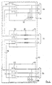
- Figure 1 shows the electrical diagram of a three-phase switchboard, with inlet cells equipped with an arc shorting device.
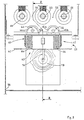
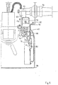
- Figure 2 is a sectional view of the short-circuiting device along line 2-2 of the figure 3, the short-circuiting device being in the open position.
- FIG. 3 shows an elevation view of the short-circuiting device, shown in open position.
- Figure 4 is a view identical to Figure 3 in the closed position of the short-circuiting device.
- Figure 5 is a view identical to Figure 2 in the closed position of the short-circuiting device.
- a three-phase medium or high voltage electrical panel 10 is composed two functional units or incoming cells 12, 14 electrically interconnected by a busbar 18 common to a third functional unit or cubicle 16 at the start and protection.
- the general structure of Table 10 is described by way of example in the French patent 2,507,835 to the applicant.
- Each inlet cell 12, 14 comprises a three-phase switch or circuit breaker 20, 22 to three positions, connected between the busbar 18 and input cables 24, 26 connected to the network, and an arc shorting device 28, 30, which will be described in detail below.
- the flow cell 16 comprises a three-phase switch 32 with three positions, connected by fuse circuit breakers 34 to output cables 36 for supplying a receiver, in particular a transformer (not shown). It is clear that the switch assembly 32 and fuse circuit breaker 34 can be replaced by a circuit breaker.
- Each switch 20, 22, 32 is provided by phase with a movable contact cooperating with a mechanism for occupying either a closed position, an open position, or a grounding position.
- All of the live conductive parts of the equipment are housed in a metallic and closed casing 38, filled with insulating gas with high dielectric strength, in particular sulfur hexafluoride SF6.
- the arc shorting device 28 of the incoming cell 12 is identical to that 30 of the other arrival cell 14, and is entirely housed at inside the sealed envelope 38.
- a fixed frame 40 is secured to the internal wall of the casing 38, and serves as a support for the short-circuiting device 28, which comprises a moving element 42 having a pair of contacts 44, 46 in bridges cooperating with three fixed contacts 48, 50, 52 arranged on the internal parts of the bushings 54 in connection with the input cables 24 of the corresponding phases.
- the fixed contacts 48, 50, 52 have a cylindrical section, being separated from each other others inside the envelope 38 by two bridging intervals 56, 58 (FIG. 3) having identical widths.
- Each bridge contact 44, 46 of the mobile assembly 42 is equipped with two ramps 44a, 44b; 46a, 46b lateral, forming an acute angle between them, to form a wedge coming insert into the corresponding interval 56, 58 in the closed position ( Figure 4).
- the lateral faces of the corner engage against two parallel generatrices of the fixed contacts 48, 50, 52 cylindrical.
- the moving element 42 is associated with an energy storage mechanism 60, comprising a telescopic guide 62 for supporting two compression springs 64, 66, and a lever attachment 68 mounted with limited pivoting on an axis 70 between an armed position (figure 2) and a triggered position ( Figure 5).
- the two springs 64, 66 bear on the chassis 40 by urging the movable slide 72 of the telescopic guide 62 towards the fixed contacts 48, 50, 52, the bridge contacts 44, 46 being arranged on the slide 72 to the opposite of the springs 64, 66.
- the hooking lever 68 comprises a hook 74 with a rounded internal edge cooperating in armed position with a retaining roller 75 secured to the slide 72.
- a control tongue 76 Opposite the hook 74 is a control tongue 76 controlled by a pressure sensor trigger 78, which releases the catch lever 68 in urging hook 74 to the triggered position in the event of rapid pressure rise SF6 gas inside the casing 38.
- the pressure detector 78 is housed inside the casing 38, and is provided with a membrane 80 made of waterproof deformable material, intended to transform the variation of pressure in a mechanical force F1 exerted on the lever control tab 76 attachment 68.
- the membrane 80 is mounted in leaktight manner on an opening of a chamber 82 auxiliary communicating with the internal volume of the casing 38 through an orifice 84 decompression calibrated, the reference volume of chamber 82 being less than remaining volume of the casing 38.
- the leakage rate through the calibrated orifice 84 makes it possible to equalize slow pressure variations between the two volumes, for example due to variations temperature, and to avoid any rupture of the membrane 80 during the operations of placing under vacuum and filling of the casing 38 with the insulating gas SF6.
- the membrane 80 and the tongue 76 of the hooking lever 68 are protected from the parts under voltage by a cover 86 of conductive material, located at ground potential.
- the presence of this cover 86 improves the dielectric strength of the panel 10 and places the detector pressure 78 in an area with almost zero electric field, which avoids any arcing internal between the live parts, and a sensitive element of the short-circuiting device 28.
- the locking zone of the roller 75 retained by the hooking lever 68 is located in a middle position, and in particular in the central plane of symmetry of the bridge contacts 44, 46, and springs 64, 66, so as to obtain a uniform distribution of the force of holding the slide 72 for the compression action of the springs 64, 66 in position army of mechanism 60.
- the bridge contacts 44, 46 and the fixed contacts 48, 50, 52 are made of copper, without special coating.
- the operation of the short-circuiting device 28 is as follows: During the normal operating period of the electrical panel 10, the gas pressure SF6 inside the casing 38 is constant, and reaches a value close to 1 to 2 bars.
- the bridge contacts 44, 46 are open ( Figures 2 and 3), and are kept permanently in this position by the action of locking the slide 72 in the armed state of the mechanism 60 with energy accumulation.
- priming can occur, for example between conductors of the busbar 18, which causes the formation of an internal arc, and a rapid rise in pressure of the SF6 gas inside envelope 38.
- This results in a pressure differential with respect to the reference volume of the auxiliary chamber 82, causing the membrane 80 to sink in the direction of arrow F1 ( Figure 5).
- the driving-in movement of the membrane 80 causes the pivoting of the hooking lever 68 in the direction of the arrow F2 around the axis 70, so as to release the roller 75 for the passage of the mechanism 60 in the triggered state.
- the wedge shape of the contact bridges 44, 46 makes it possible to obtain contact pressures greater than the thrust of the springs 64, 66, and withstand the repulsion forces electrodynamics without the use of oversized springs.
- the specific dimensioning of the fixed contacts 48, 50, 52 and contact bridges 44, 46 allows them to withstand the short-circuit current during the duration corresponding to the intervention time of the protections upstream of the network.
- the presence of the grounded conductive cover 86 confines an electric field area zero, in which the sensitive elements of the pressure detector 78 are arranged.
- the arc internal fails to penetrate this area, and the operation of the short-circuiting device 28 is safely ensured regardless of where the arc arises inside the envelope 38.
Landscapes
- Engineering & Computer Science (AREA)
- Power Engineering (AREA)
- Gas-Insulated Switchgears (AREA)
- Breakers (AREA)
- Arc-Extinguishing Devices That Are Switches (AREA)
Description
- un mécanisme à accumulation d'énergie associé à un équipage mobile de support de premiers moyens de contacts susceptibles de coopérer avec des seconds moyens de contacts fixés aux pièces conductrices,
- un dispositif de déclenchement doté d'un levier d'accrochage déplaçable entre une position armée correspondant à la séparation desdits premiers et seconds moyens de contact, et une position déclenchée de libération du mécanisme pour la fermeture desdits moyens de contacts,
- un détecteur de pression sensible à la variation de pression du gaz à l'intérieur de l'enveloppe pour provoquer le passage du levier d'accrochage de la position armée vers la position déclenchée au-delà d'un seuil prédéterminé faisant suite à la formation d'un arc interne,
- l'ensemble des organes du mécanisme, du dispositif de déclenchement, et du détecteur de pression étant entièrement contenu à l'intérieur de l'enveloppe fermée.
- absence de fonctionnement intempestif sous l'action des différents agents susceptibles d'affecter l'équipement électrique;
- fonctionnement assuré en cas d'arc interne d'intensité et de durée comprises entre des valeurs prédéterminées et assignées par le constructeur.
Claims (7)
- Appareillage électrique multipolaire à haute tension, ayant des pièces conductrices sous tension logées dans une enveloppe (38) métallique étanche, remplie de gaz isolant à rigidité diélectrique élevée, notamment de l'hexafluorure de soufre, ledit appareillage étant équipé d'un dispositif court-circuiteur (28, 30) d'arc, rendu actif en cas d'amorçage interne suite à une défaillance de l'isolation gazeuse, et comportant :caractérisé en ce queun mécanisme (60) à accumulation d'énergie associé à un équipage mobile (42) de support de premiers moyens de contacts (44, 46) susceptibles de coopérer avec des seconds moyens de contacts (48, 50, 52) fixés aux pièces conductrices,un dispositif de déclenchement doté d'un levier d'accrochage (68) déplaçable entre une position armée correspondant à la séparation desdits premiers et seconds moyens de contact, et une position déclenchée de libération du mécanisme (60) pour la fermeture desdits moyens de contacts,un détecteur de pression (78) sensible à la variation de pression du gaz à l'intérieur de l'enveloppe (38) pour provoquer le passage du levier d'accrochage (68) de la position armée vers la position déclenchée au-delà d'un seuil prédéterminé faisant suite à la formation d'un arc interne,l'ensemble des organes du mécanisme (60), du dispositif de déclenchement, et du détecteur de pression (78) étant entièrement contenu à l'intérieur de l'enveloppe (38) fermée,
les seconds moyens de contacts (48, 50, 52) sont formés par trois plots fixes, de sections sensiblement cylindriques, séparés les uns des autres par deux intervalles (56, 58) de pontage, et que les premiers moyens de contacts (44, 46) comportent une paire de ponts de contacts mobiles destinés à s'insérer en position déclenchée du levier d'accrochage (68), dans les intervalles (56, 58) correspondants pour venir en engagement avec des génératrices des plots fixes en assurant le court-circuitage entre les phases des pièces conductrices. - Appareillage électrique selon la revendication 1, caractérisé en ce que chaque pont de contact (44, 46) est conformé en coin, ayant deux rampes (44a, 44b; 46a, 46b) disposées à angle aigu au droit de l'intervalle de pontage (56, 58) correspondant, de manière à résister aux efforts de répulsion électrodynamique lors du court-circuitage.
- Appareillage électrique selon la revendication 1 ou 2, caractérisé en ce que le levier d'accrochage (68) comporte un crochet (74) coopérant en position armée avec un galet (75) de retenue fixé à un coulisseau (72) de l'équipage mobile (42), la zone de verrouillage du galet (75) étant située dans le plan central de symétrie des deux ponts de contacts (44, 46), et que le mécanisme (60) est pourvu de deux ressorts (64, 66) sollicitant le coulisseau (72) en direction des seconds moyens de contacts (48, 50, 52) lors du déplacement du levier d'accrochage (68) vers la position déclenchée.
- Appareillage électrique selon l'une des revendications 1 à 3, caractérisé en ce que le détecteur de pression (78) est composé d'une membrane (80) en matériau déformable, montée à étanchéité sur une ouverture d'une chambre (82) auxiliaire, laquelle communique avec le volume restant de l'enveloppe (38) à travers un orifice (84) calibré de décompression, le volume de référence de ladite chambre (82) étant inférieur à celui de l'enveloppe (38).
- Appareillage électrique selon la revendication 4, caractérisé en ce que la membrane (80) du détecteur de pression (78) est accouplée à une languette (76) de commande du levier d'accrochage (68) pivotant.
- Appareillage électrique selon l'une des revendications 1 à 5, caractérisé en ce qu'un capot (86) en matériau conducteur recouvre le détecteur de pression (78) pour former une zone à champ électrique quasi-nul, ledit capot (86) étant connecté électriquement à la terre.
- Appareillage électrique selon l'une des revendications 1 à 6, caractérisé en ce que le dispositif court-circuiteur (28, 30) est supporté par un châssis (40) solidarisé à la paroi interne de l'enveloppe (38) métallique.
Applications Claiming Priority (2)
| Application Number | Priority Date | Filing Date | Title |
|---|---|---|---|
| FR9412377A FR2725844B1 (fr) | 1994-10-12 | 1994-10-12 | Appareillage electrique a haute tension et a isolement gazeux equipe d'un dispositif court-circuiteur d'arc |
| FR9412377 | 1994-10-12 |
Publications (2)
| Publication Number | Publication Date |
|---|---|
| EP0707364A1 EP0707364A1 (fr) | 1996-04-17 |
| EP0707364B1 true EP0707364B1 (fr) | 1998-11-04 |
Family
ID=9467933
Family Applications (1)
| Application Number | Title | Priority Date | Filing Date |
|---|---|---|---|
| EP19950410093 Expired - Lifetime EP0707364B1 (fr) | 1994-10-12 | 1995-09-05 | Appareillage électrique à haute tension et à isolement gazeux équipé d'un dispositif court-circuiteur d'arc |
Country Status (7)
| Country | Link |
|---|---|
| EP (1) | EP0707364B1 (fr) |
| CN (1) | CN1059978C (fr) |
| DE (1) | DE69505772T2 (fr) |
| ES (1) | ES2126235T3 (fr) |
| FR (1) | FR2725844B1 (fr) |
| NO (1) | NO308390B1 (fr) |
| TW (1) | TW303473B (fr) |
Cited By (2)
| Publication number | Priority date | Publication date | Assignee | Title |
|---|---|---|---|---|
| EP1806817A1 (fr) | 2006-01-09 | 2007-07-11 | Luis Gonzalo Flores Losada | Appareillage électrique immergé dans l'huile avec un dispositif de sécurité à court-circuit |
| CN104409970A (zh) * | 2014-11-28 | 2015-03-11 | 国家电网公司 | 开关柜 |
Families Citing this family (4)
| Publication number | Priority date | Publication date | Assignee | Title |
|---|---|---|---|---|
| DE10031561A1 (de) * | 2000-06-28 | 2002-01-10 | Alstom | Störlichtbogenbegrenzer für eine gasisolierte Schaltanlage |
| FR2955983A1 (fr) * | 2010-02-01 | 2011-08-05 | Mining Res & Dev | Dispositif de protection d'un arc electrique |
| EP2551974A1 (fr) * | 2011-07-25 | 2013-01-30 | Eaton Industries (Netherlands) B.V. | Installation de commutation avec dispositif de court-circuit à pression contrôlée |
| DE102013109938A1 (de) * | 2013-09-10 | 2015-03-12 | Fritz Driescher KG Spezialfabrik für Elektrizitätswerksbedarf GmbH & Co | Schaltanlage mit Störlichtbogenbegrenzer |
Family Cites Families (4)
| Publication number | Priority date | Publication date | Assignee | Title |
|---|---|---|---|---|
| FR2507835A1 (fr) | 1981-06-16 | 1982-12-17 | Merlin Gerin | Cellule blindee a isolement gazeux pour poste electrique a moyenne tension |
| DE3131417A1 (de) * | 1981-08-07 | 1983-02-24 | Brown, Boveri & Cie Ag, 6800 Mannheim | Betaetigungsvorrichtung fuer einen erdungsschalter oder einen kurzschliesser in drucklos gekapselten schaltanlagenteilen von hochspannungs- oder mittelspannungsschalt- und -verteileranlagen |
| FR2649531B1 (fr) * | 1989-07-04 | 1995-11-10 | Alsthom Gec | Disjoncteur a haute ou moyenne tension |
| NO175173C (no) * | 1992-02-03 | 1994-09-07 | Abb Distribusjon As | Anordning ved automatisk jordslutter |
-
1994
- 1994-10-12 FR FR9412377A patent/FR2725844B1/fr not_active Expired - Fee Related
-
1995
- 1995-09-05 DE DE1995605772 patent/DE69505772T2/de not_active Expired - Lifetime
- 1995-09-05 EP EP19950410093 patent/EP0707364B1/fr not_active Expired - Lifetime
- 1995-09-05 ES ES95410093T patent/ES2126235T3/es not_active Expired - Lifetime
- 1995-09-26 TW TW84110029A patent/TW303473B/zh active
- 1995-10-11 NO NO954044A patent/NO308390B1/no not_active IP Right Cessation
- 1995-10-12 CN CN95116157A patent/CN1059978C/zh not_active Expired - Fee Related
Cited By (3)
| Publication number | Priority date | Publication date | Assignee | Title |
|---|---|---|---|---|
| EP1806817A1 (fr) | 2006-01-09 | 2007-07-11 | Luis Gonzalo Flores Losada | Appareillage électrique immergé dans l'huile avec un dispositif de sécurité à court-circuit |
| US7755868B2 (en) | 2006-01-09 | 2010-07-13 | Luis Gonzalo Flores Losada | Electrical equipment for distribution network |
| CN104409970A (zh) * | 2014-11-28 | 2015-03-11 | 国家电网公司 | 开关柜 |
Also Published As
| Publication number | Publication date |
|---|---|
| FR2725844A1 (fr) | 1996-04-19 |
| DE69505772T2 (de) | 1999-05-27 |
| NO308390B1 (no) | 2000-09-04 |
| CN1129846A (zh) | 1996-08-28 |
| CN1059978C (zh) | 2000-12-27 |
| ES2126235T3 (es) | 1999-03-16 |
| EP0707364A1 (fr) | 1996-04-17 |
| NO954044L (no) | 1996-04-15 |
| FR2725844B1 (fr) | 1996-12-13 |
| NO954044D0 (no) | 1995-10-11 |
| DE69505772D1 (de) | 1998-12-10 |
| TW303473B (fr) | 1997-04-21 |
Similar Documents
| Publication | Publication Date | Title |
|---|---|---|
| EP0225207B1 (fr) | Chaîne cinématique de transmission entre le mécanisme de commande et les pôles d'un disjoncteur électrique à boîtier isolant moulé | |
| CN101454859B (zh) | 短路开关装置 | |
| CN101796604B (zh) | 具有短路系统的低压、中压或高压开关设备组件 | |
| EP0847586B1 (fr) | Disjoncteur hybride a haute tension | |
| EP0444568B1 (fr) | Disjoncteur à coupure assistée par varistance | |
| FR2582857A1 (fr) | Disjoncteur unipolaire et neutre a effet shunt | |
| EP0707364B1 (fr) | Appareillage électrique à haute tension et à isolement gazeux équipé d'un dispositif court-circuiteur d'arc | |
| EP0277848B1 (fr) | Disjoncteur polyphasé à autoexpansion équipé d'une chambre de coupure blindée par pole | |
| EP0270389B1 (fr) | Interrupteur rotatif multipolaire à isolement gazeux | |
| EP0165184B1 (fr) | Poste blindé triphasé à isolement gazeux | |
| EP0924827B1 (fr) | Cellule à moyenne tension à isolement gazeux, et à tenue diélectrique élevée | |
| FR2703825A1 (fr) | Disjoncteur en boîtier moulé avec unité d'adaptation des transformateurs de courant. | |
| EP0053973B1 (fr) | Disjoncteur miniature à haut pouvoir de coupure | |
| EP1122848B1 (fr) | Dispositif de protection perfectionne contre les effects des défauts internes d'un transformateur triphase | |
| EP0130851A1 (fr) | Appareil de protection contre les surtensions pour une installation ou un réseau électrique à basse tension | |
| EP0338382B1 (fr) | Cellule pour poste blindé à moyenne et haute tension et poste constitué de telles cellules | |
| EP0433183A1 (fr) | Interrupteur tripolaire à haute tension et à isolement gazeux | |
| WO2006072737A2 (fr) | Appareil de protection d'une installation electrique a capacite de coupure amelioree | |
| FR2553926A1 (fr) | Disjoncteur haute tension a resistances de fermeture | |
| EP0348312B1 (fr) | Poste blindé pour réseau à haute tension | |
| FR2547107A1 (fr) | Sectionneur d'isolement blinde | |
| FR2589625A1 (fr) | Chaine cinematique de transmission entre le mecanisme de commande et les poles d'un disjoncteur electrique | |
| FR2650078A1 (fr) | Systeme de detection de defaut d'isolement d'une ligne de distribution d'energie electrique moyenne tension | |
| FR2711271A1 (fr) | Appareillage de protection formé par l'association d'un disjoncteur en série avec un effecteur. | |
| FR2595003A1 (fr) | Appareillage electrique multipolaire a enveloppe commune et a isolement gazeux |
Legal Events
| Date | Code | Title | Description |
|---|---|---|---|
| PUAI | Public reference made under article 153(3) epc to a published international application that has entered the european phase |
Free format text: ORIGINAL CODE: 0009012 |
|
| AK | Designated contracting states |
Kind code of ref document: A1 Designated state(s): DE ES GB IT NL SE |
|
| 17P | Request for examination filed |
Effective date: 19960924 |
|
| GRAG | Despatch of communication of intention to grant |
Free format text: ORIGINAL CODE: EPIDOS AGRA |
|
| 17Q | First examination report despatched |
Effective date: 19971117 |
|
| GRAG | Despatch of communication of intention to grant |
Free format text: ORIGINAL CODE: EPIDOS AGRA |
|
| GRAH | Despatch of communication of intention to grant a patent |
Free format text: ORIGINAL CODE: EPIDOS IGRA |
|
| GRAH | Despatch of communication of intention to grant a patent |
Free format text: ORIGINAL CODE: EPIDOS IGRA |
|
| GRAA | (expected) grant |
Free format text: ORIGINAL CODE: 0009210 |
|
| AK | Designated contracting states |
Kind code of ref document: B1 Designated state(s): DE ES GB IT NL SE |
|
| REF | Corresponds to: |
Ref document number: 69505772 Country of ref document: DE Date of ref document: 19981210 |
|
| GBT | Gb: translation of ep patent filed (gb section 77(6)(a)/1977) |
Effective date: 19990112 |
|
| ITF | It: translation for a ep patent filed | ||
| REG | Reference to a national code |
Ref country code: ES Ref legal event code: FG2A Ref document number: 2126235 Country of ref document: ES Kind code of ref document: T3 |
|
| PLBE | No opposition filed within time limit |
Free format text: ORIGINAL CODE: 0009261 |
|
| STAA | Information on the status of an ep patent application or granted ep patent |
Free format text: STATUS: NO OPPOSITION FILED WITHIN TIME LIMIT |
|
| 26N | No opposition filed | ||
| REG | Reference to a national code |
Ref country code: GB Ref legal event code: IF02 |
|
| PGFP | Annual fee paid to national office [announced via postgrant information from national office to epo] |
Ref country code: GB Payment date: 20020904 Year of fee payment: 8 |
|
| PGFP | Annual fee paid to national office [announced via postgrant information from national office to epo] |
Ref country code: ES Payment date: 20020927 Year of fee payment: 8 |
|
| PG25 | Lapsed in a contracting state [announced via postgrant information from national office to epo] |
Ref country code: GB Free format text: LAPSE BECAUSE OF NON-PAYMENT OF DUE FEES Effective date: 20030905 |
|
| PG25 | Lapsed in a contracting state [announced via postgrant information from national office to epo] |
Ref country code: ES Free format text: LAPSE BECAUSE OF NON-PAYMENT OF DUE FEES Effective date: 20030906 |
|
| GBPC | Gb: european patent ceased through non-payment of renewal fee | ||
| REG | Reference to a national code |
Ref country code: ES Ref legal event code: FD2A Effective date: 20030906 |
|
| PG25 | Lapsed in a contracting state [announced via postgrant information from national office to epo] |
Ref country code: IT Free format text: LAPSE BECAUSE OF NON-PAYMENT OF DUE FEES;WARNING: LAPSES OF ITALIAN PATENTS WITH EFFECTIVE DATE BEFORE 2007 MAY HAVE OCCURRED AT ANY TIME BEFORE 2007. THE CORRECT EFFECTIVE DATE MAY BE DIFFERENT FROM THE ONE RECORDED. Effective date: 20050905 |
|
| PGFP | Annual fee paid to national office [announced via postgrant information from national office to epo] |
Ref country code: NL Payment date: 20090903 Year of fee payment: 15 |
|
| PGFP | Annual fee paid to national office [announced via postgrant information from national office to epo] |
Ref country code: DE Payment date: 20100918 Year of fee payment: 16 |
|
| REG | Reference to a national code |
Ref country code: NL Ref legal event code: V1 Effective date: 20110401 |
|
| PG25 | Lapsed in a contracting state [announced via postgrant information from national office to epo] |
Ref country code: NL Free format text: LAPSE BECAUSE OF NON-PAYMENT OF DUE FEES Effective date: 20110401 |
|
| REG | Reference to a national code |
Ref country code: DE Ref legal event code: R119 Ref document number: 69505772 Country of ref document: DE Effective date: 20130403 |
|
| PG25 | Lapsed in a contracting state [announced via postgrant information from national office to epo] |
Ref country code: DE Free format text: LAPSE BECAUSE OF NON-PAYMENT OF DUE FEES Effective date: 20130403 |
|
| PGFP | Annual fee paid to national office [announced via postgrant information from national office to epo] |
Ref country code: SE Payment date: 20130911 Year of fee payment: 19 |
|
| REG | Reference to a national code |
Ref country code: SE Ref legal event code: EUG |
|
| PG25 | Lapsed in a contracting state [announced via postgrant information from national office to epo] |
Ref country code: SE Free format text: LAPSE BECAUSE OF NON-PAYMENT OF DUE FEES Effective date: 20140906 |