EP0707372A1 - Elektrischer Generator mit Frequenzanpassungsvorrichtung - Google Patents
Elektrischer Generator mit Frequenzanpassungsvorrichtung Download PDFInfo
- Publication number
- EP0707372A1 EP0707372A1 EP95402260A EP95402260A EP0707372A1 EP 0707372 A1 EP0707372 A1 EP 0707372A1 EP 95402260 A EP95402260 A EP 95402260A EP 95402260 A EP95402260 A EP 95402260A EP 0707372 A1 EP0707372 A1 EP 0707372A1
- Authority
- EP
- European Patent Office
- Prior art keywords
- machine
- rectifier
- bridges
- machine according
- minus
- Prior art date
- Legal status (The legal status is an assumption and is not a legal conclusion. Google has not performed a legal analysis and makes no representation as to the accuracy of the status listed.)
- Granted
Links
Images

Classifications
-
- H—ELECTRICITY
- H02—GENERATION; CONVERSION OR DISTRIBUTION OF ELECTRIC POWER
- H02K—DYNAMO-ELECTRIC MACHINES
- H02K11/00—Structural association of dynamo-electric machines with electric components or with devices for shielding, monitoring or protection
- H02K11/04—Structural association of dynamo-electric machines with electric components or with devices for shielding, monitoring or protection for rectification
- H02K11/049—Rectifiers associated with stationary parts, e.g. stator cores
- H02K11/05—Rectifiers associated with casings, enclosures or brackets
Definitions
- the invention relates to a rotating machine, generating electrical energy.
- the invention relates more particularly to a rotating machine, generator of electrical energy, supplying an electrical network, directly driven by a gas turbine and / or a steam turbine, and debiting in the network by means of adaptation devices. from the frequency generated by the machine to the network frequency. In service, these devices heat up significantly. It is therefore necessary to have associated cooling means.
- adaptation devices are arranged in dedicated cabinets, external to said machine, and comprising cooling means. This results in significant overall dimensions for the rotating machine / cabinets of frequency adaptation device.
- One of the aims of the present invention is to significantly reduce the size of the rotating machine / frequency adaptation device cabinets assembly.
- Another object of the present invention is to use at least part of the cooling means of said rotary machine to cool the part of the adaptation device included in the stator of the rotary machine.
- Static frequency matching devices generally include diode / thyristor bridges. Such a device is composed in a known manner of a bridge phase rectifier, known as a machine bridge, with possible inductance and an inverter bridge, known as a network bridge.
- the subject of the invention is a polyphase generator of electrical energy, comprising a rotor and a stator arranged around an axis of rotation of the rotor, cooled by at least one circulation of cooling fluid, said machine delivering in a network at at least through a device for adapting the frequency generated by the machine to the network frequency, characterized in that the stator contains at least part of the components of the frequency matching device.
- the part of the components of the adaptation device contained in the stator is located so as to benefit from said circulation of coolant of the machine.
- said part of the components of the adaptation device comprises a plurality of rectifier machine bridges having a plus pole, a minus pole, and a midpoint, each phase being connected to the midpoint of one of the machine bridges rectifier.
- the machine is of the polygonal stator winding type, comprising at least one polygonal stator winding with N vertices, each vertex defining a phase, all the plus poles and all the minus poles of the rectifier machine bridges being connected respectively a common ring plus and a common ring minus, centered on the axis of the rotor, surrounding the coil heads of the stator winding of polygonal type.
- the rectifier bridges are located around the coil heads of the stator winding of the polygonal type.
- Each rectifier bridge is opposite, and connected to a coil head constituting one of the vertices of the polygonal stator winding.
- the machine according to the invention comprises two respectively plus and minus terminals, respectively from the plus ring and the minus ring, intended to be connected to an inverter network bridge, possibly through an inductor.
- the inverter network bridge as well as the possible inductance, are also located to benefit from the circulation of cooling fluid.
- the rectifier bridges are mounted on finned radiators, said finned radiators being mounted on insulating support shims around the coil heads.
- the machine is of the three-phase stator winding type, comprising 2N three-phase stator windings, each phase of each winding being connected to the midpoint of a rectifier machine bridge, the minus poles and the plus poles of the machine bridges rectifier of the same winding being respectively connected together and coupled to a minus terminal and to a plus terminal.
- the three rectifier bridges of each winding constitute a block, coupled to an inverter network bridge through a loop inductance.
- the rectifier machine bridge blocks are located in spaces in the machine casing to replace the components that have been removed due to the use of an energy production group in which the turbine directly drives the rotating generator machine, without reducer. interposed.
- the rectifier bridges benefit from said fluid circulation.
- the rectifier bridges are mounted on finned radiators.
- a first advantage of the present invention is the significant reduction in the size of the rotating machine / cabinets of frequency adaptation device assembly. Indeed, at least part of the device being integrated in the stator of the machine, the dimensions of the cabinets and of the cooling means are significantly reduced.
- Another advantage of the invention is a significant reduction in the price of the rotating machine / cabinets of frequency adaptation device assembly.
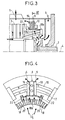
- the rotary machine 1 shown diagrammatically in FIG. 1 is a polyphase electric power generator and comprises a rotor part 2 and a stator part 3 of axis 4.
- the machine comprises, in known manner, at least one circulation 5 of cooling gas intended to cool the stator parts 3 and rotor 2. Still in known manner, the machine feeds into a network 6, through a device 7 for adapting the frequency generated by the machine 1 to the frequency of the network 6.
- the rotor part 2 of the machine 1 is advantageously driven directly and without reduction gear by a gas or steam turbine 8.
- the stator part 3 comprises at least one part 9 of the components of the frequency adaptation device 7.
- the part 9 of the components of the frequency adaptation device 7 is located in the circulation 5 of cooling fluid of the rotary machine 1, which in the example described is air.
- the part 9 of the components of the frequency adaptation device 7 may comprise means 10, such as a finned radiator to promote heat exchange with the circulation of air.
- the part 9 of the components of the frequency adaptation device 7 is integrated into the stator part 3 of the machine 1 without increasing the volume of the said machine 1.
- the frequency adaptation device 7 comprises, in known manner, a plurality of rectifier machine bridges 9 having a plus pole 12, a minus pole 11, and a midpoint 13, each phase 14 being connected to the midpoint 13 of one of the rectifier machine bridges 9.
- These rectifier machine bridges 9 comprise, for example, two rectifier elements 15 in series. These elements can be controllable, semi-controllable or non-controllable.
- the rotary machine 1 is of the type with polygonal stator winding, comprising at least one polygonal stator winding with N vertices.
- the winding comprises coil heads 18, located at the longitudinal ends of the stator part 3.
- Each vertex 13 of the polygonal stator winding defines a phase 14 corresponding to a main coil head 18a.
- All the plus 12 poles and all the minus 11 poles of the rectifier machine bridges 9 are respectively connected to a common plus 17 ring and to a common minus 16 ring, centered on the axis 4 of the machine 1, surrounding the coil heads 18 of the polygonal type stator winding.
- the rectifier bridges 9 are located on a circle centered on the axis 4 of the machine, surrounding the coil heads 18 of the stator winding of the polygonal type.
- each rectifier machine bridge 9 is opposite, and connected to a main coil head 18a constituting one of the vertices of the polygonal stator winding.
- the rectifier machine bridges 9 are mounted on fin radiators 10, said fin radiators 10 being mounted on insulating support shims 22 around the coil heads 18.
- the circulation of air passing through the spaces 25 inter-head cools the rectifier machine bridges 9 and their associated radiator 10.
- the machine also comprises two external terminals, plus and minus respectively, respectively from the plus ring 17 and the minus ring 16, intended to be connected to an inverter network bridge 20 through an optional loop inductance 21.
- the inverter network bridge 20 is also arranged around the coil heads or in the cooling circuit of the machine.
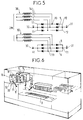
- the machine is of the three-phase stator winding type, comprising 2N three-phase stator windings 30.
- Each phase 14 of each winding 30 is connected to the midpoint 13 of a rectifier machine bridge 9, the minus poles 11 and the plus poles 12 of the rectifier machine bridges 9 of the same winding 30 being connected together respectively to a common terminal less 32 and a common terminal plus 31.
- each winding 30 there is a block 33 of three rectifier machine bridges 9.
- This block is advantageously mounted on a fin radiator 10 in order to improve the heat transfer.
- the blocks 33 of rectifier bridges, of the Graetz type can either be each connected to an associated inverter bridge, which gives 2N inverter bridges to then couple together, or coupled together, in parallel or series-parallel, to then flow into a single inverter bridge.
- the inverter network bridge can be internal or external to the machine.
- the blocks 33 of rectifier machine bridges 9 are located in spaces in the machine casing to replace the components which have been eliminated due to the use of an energy production group in which the turbine directly drives the rotating generator machine, without interposed reducer.
- These rectifier machine bridge blocks are located in the machine's cooling circuit.
Landscapes
- Engineering & Computer Science (AREA)
- Power Engineering (AREA)
- Motor Or Generator Cooling System (AREA)
- Control Of Eletrric Generators (AREA)
- Circuit Arrangements For Discharge Lamps (AREA)
- Circuit For Audible Band Transducer (AREA)
- Synchronous Machinery (AREA)
- Apparatuses For Generation Of Mechanical Vibrations (AREA)
- Sanitary Device For Flush Toilet (AREA)
- Supply And Distribution Of Alternating Current (AREA)
- Diaphragms For Electromechanical Transducers (AREA)
- Amplifiers (AREA)
Applications Claiming Priority (2)
| Application Number | Priority Date | Filing Date | Title |
|---|---|---|---|
| FR9412294 | 1994-10-14 | ||
| FR9412294A FR2725852B1 (fr) | 1994-10-14 | 1994-10-14 | Generatrice d'energie electrique munie de dispositifs d'adaptation de la frequence |
Publications (2)
| Publication Number | Publication Date |
|---|---|
| EP0707372A1 true EP0707372A1 (de) | 1996-04-17 |
| EP0707372B1 EP0707372B1 (de) | 1998-07-08 |
Family
ID=9467872
Family Applications (1)
| Application Number | Title | Priority Date | Filing Date |
|---|---|---|---|
| EP95402260A Expired - Lifetime EP0707372B1 (de) | 1994-10-14 | 1995-10-09 | Elektrischer Generator mit Frequenzanpassungsvorrichtung |
Country Status (8)
| Country | Link |
|---|---|
| EP (1) | EP0707372B1 (de) |
| JP (1) | JPH08182396A (de) |
| AT (1) | ATE168228T1 (de) |
| DE (1) | DE69503333T2 (de) |
| ES (1) | ES2120148T3 (de) |
| FI (1) | FI954828A7 (de) |
| FR (1) | FR2725852B1 (de) |
| RU (1) | RU2172550C2 (de) |
Cited By (4)
| Publication number | Priority date | Publication date | Assignee | Title |
|---|---|---|---|---|
| FR2919126A1 (fr) * | 2007-07-18 | 2009-01-23 | Valeo Equip Electr Moteur | Dispositif d'alimentation pour un alternateur de vehicule automobile et alternateur mettant en oeuvre un tel dispositif |
| US7633195B2 (en) | 2002-03-18 | 2009-12-15 | Alstom Technology Ltd. | Electrical machine with integrated electronic power device |
| EP2133980A1 (de) | 2008-06-13 | 2009-12-16 | ALSTOM Technology Ltd | Mehrphasengenerator mit Umrichtereinheit |
| US7880350B2 (en) | 2008-06-13 | 2011-02-01 | Alstom Technology Ltd | Multi phase generator arrangement |
Families Citing this family (1)
| Publication number | Priority date | Publication date | Assignee | Title |
|---|---|---|---|---|
| US8103225B2 (en) * | 2007-05-04 | 2012-01-24 | Astrium Limited | Multiport amplifiers in communications satellites |
Citations (8)
| Publication number | Priority date | Publication date | Assignee | Title |
|---|---|---|---|---|
| DE1065921B (de) * | 1959-09-24 | |||
| FR1357374A (fr) * | 1963-05-17 | 1964-04-03 | Siemens Ag | Dispositif pour produire du courant continu |
| FR2438936A1 (fr) * | 1978-10-09 | 1980-05-09 | Thyssen Industrie | Machine electrique avec un rotor, un stator a enroulement polyphase et un dispositif de commutation permutant sur un nombre de phases different |
| AT382271B (de) * | 1985-01-24 | 1987-02-10 | Aichholzer Gerhard Dr | Anlaufschaltungsanordnung fuer einen kommutatorlosen gleichstrom-reihenschlussmotor |
| DE3528347A1 (de) * | 1985-08-07 | 1987-02-19 | Kaick A Ettlingen Gmbh Van | Fluessigkeitsgekuehlter elektrischer stromerzeuger |
| SU1471258A1 (ru) * | 1986-02-26 | 1989-04-07 | А.С.Айнварг | Генератор регулируемой частоты |
| EP0329368A1 (de) * | 1988-02-15 | 1989-08-23 | Techmarex (Proprietary) Limited | Generator |
| WO1992014298A1 (en) * | 1991-02-01 | 1992-08-20 | U.S. Windpower, Inc. | Variable speed wind turbine |
-
1994
- 1994-10-14 FR FR9412294A patent/FR2725852B1/fr not_active Expired - Lifetime
-
1995
- 1995-10-09 DE DE69503333T patent/DE69503333T2/de not_active Expired - Lifetime
- 1995-10-09 EP EP95402260A patent/EP0707372B1/de not_active Expired - Lifetime
- 1995-10-09 ES ES95402260T patent/ES2120148T3/es not_active Expired - Lifetime
- 1995-10-09 AT AT95402260T patent/ATE168228T1/de active
- 1995-10-11 FI FI954828A patent/FI954828A7/fi not_active Application Discontinuation
- 1995-10-13 JP JP7265797A patent/JPH08182396A/ja active Pending
- 1995-10-13 RU RU95118098/09A patent/RU2172550C2/ru not_active IP Right Cessation
Patent Citations (8)
| Publication number | Priority date | Publication date | Assignee | Title |
|---|---|---|---|---|
| DE1065921B (de) * | 1959-09-24 | |||
| FR1357374A (fr) * | 1963-05-17 | 1964-04-03 | Siemens Ag | Dispositif pour produire du courant continu |
| FR2438936A1 (fr) * | 1978-10-09 | 1980-05-09 | Thyssen Industrie | Machine electrique avec un rotor, un stator a enroulement polyphase et un dispositif de commutation permutant sur un nombre de phases different |
| AT382271B (de) * | 1985-01-24 | 1987-02-10 | Aichholzer Gerhard Dr | Anlaufschaltungsanordnung fuer einen kommutatorlosen gleichstrom-reihenschlussmotor |
| DE3528347A1 (de) * | 1985-08-07 | 1987-02-19 | Kaick A Ettlingen Gmbh Van | Fluessigkeitsgekuehlter elektrischer stromerzeuger |
| SU1471258A1 (ru) * | 1986-02-26 | 1989-04-07 | А.С.Айнварг | Генератор регулируемой частоты |
| EP0329368A1 (de) * | 1988-02-15 | 1989-08-23 | Techmarex (Proprietary) Limited | Generator |
| WO1992014298A1 (en) * | 1991-02-01 | 1992-08-20 | U.S. Windpower, Inc. | Variable speed wind turbine |
Non-Patent Citations (1)
| Title |
|---|
| DATABASE WPI Section EI Week 8941, Derwent World Patents Index; Class X11, AN 89-299407 * |
Cited By (7)
| Publication number | Priority date | Publication date | Assignee | Title |
|---|---|---|---|---|
| US7633195B2 (en) | 2002-03-18 | 2009-12-15 | Alstom Technology Ltd. | Electrical machine with integrated electronic power device |
| FR2919126A1 (fr) * | 2007-07-18 | 2009-01-23 | Valeo Equip Electr Moteur | Dispositif d'alimentation pour un alternateur de vehicule automobile et alternateur mettant en oeuvre un tel dispositif |
| WO2009019344A3 (fr) * | 2007-07-18 | 2009-05-22 | Valeo Equip Electr Moteur | Dispositif d'alimentation pour un alternateur de vehicule automobile et alternateur mettant en oeuvre un tel dispositif |
| US8659196B2 (en) | 2007-07-18 | 2014-02-25 | Valeo Equipements Electriques Moteur | Power supply device for motor vehicle alternator and alternator employing such device |
| EP2133980A1 (de) | 2008-06-13 | 2009-12-16 | ALSTOM Technology Ltd | Mehrphasengenerator mit Umrichtereinheit |
| US7880350B2 (en) | 2008-06-13 | 2011-02-01 | Alstom Technology Ltd | Multi phase generator arrangement |
| US8049377B2 (en) | 2008-06-13 | 2011-11-01 | Alstom Technology Ltd | Multi phase generator with frequency adaptation unit |
Also Published As
| Publication number | Publication date |
|---|---|
| FI954828L (fi) | 1996-04-15 |
| FR2725852B1 (fr) | 1997-01-03 |
| ES2120148T3 (es) | 1998-10-16 |
| DE69503333T2 (de) | 1999-01-07 |
| ATE168228T1 (de) | 1998-07-15 |
| RU2172550C2 (ru) | 2001-08-20 |
| FI954828A7 (fi) | 1996-04-15 |
| EP0707372B1 (de) | 1998-07-08 |
| FI954828A0 (fi) | 1995-10-11 |
| FR2725852A1 (fr) | 1996-04-19 |
| JPH08182396A (ja) | 1996-07-12 |
| DE69503333D1 (de) | 1998-08-13 |
Similar Documents
| Publication | Publication Date | Title |
|---|---|---|
| Bauer et al. | Evaluation of electrical systems for offshore windfarms | |
| US7960948B2 (en) | Electromechanical energy conversion systems | |
| AU2012234318B2 (en) | Pole shoe | |
| EP2656487B1 (de) | Spannungsregler für eine elektrische drehmaschine, lager für eine solche maschine mit einer solchen vorrichtung und solche maschine mit einem lager | |
| FR2945679A1 (fr) | Machine rotative electrique | |
| Mekhiche et al. | High speed motor drive development for industrial applications | |
| EP3914470B1 (de) | Antriebsmodul für ein elektrisches oder hybrides fahrzeug | |
| US20180062484A1 (en) | Synchronous generator for wind turbine | |
| EP0898352A1 (de) | Generatorsatz | |
| FR2969410A1 (fr) | Dispositif regulateur de tension pour une machine electrique tournante, palier d'une telle machine equipe d'un tel dispositif et une telle machine comportant un tel palier | |
| FR2587557A1 (fr) | Systeme d'excitation statique a refroidissement par liquide pour machine electrodynamique | |
| EP0707372B1 (de) | Elektrischer Generator mit Frequenzanpassungsvorrichtung | |
| WO2019037930A1 (fr) | Machine electrique avec dispositif de refroidissement comprenant un canal partiellement subdivise | |
| EP1235332A1 (de) | Einheit bestehend aus einer elektromagnetische Bremse und deren elektische Versorgung | |
| FR2857519A1 (fr) | Machine dynamoelectrique a rotor avec poles a griffes a deux bobines et enroulement statorique segmente | |
| FR3105892A1 (fr) | Dispositif de refroidissement et moto-variateur | |
| EP3917301B1 (de) | Wechselrichtergerät | |
| FR2814003A1 (fr) | Ensemble constitue par un ralentisseur a courants de foucault et par ses moyens d'alimentation electrique | |
| FR2969413A1 (fr) | Dispositif regulateur de tension pour une machine electrique tournante, palier d'une telle machine equipe d'un tel dispositif et une telle machine comportant un tel palier | |
| FR2818821A1 (fr) | Alternateur pour vehicule automobile | |
| RU95118098A (ru) | Многофазный генератор электрической энергии | |
| WO2025016656A1 (fr) | Machine electrique a flux axial avec guide thermique entre les bobines du stator | |
| CN120566798A (zh) | 具有用于直接冷却绕组的集成的电磁泵送系统的电机 | |
| CN110994758A (zh) | 一种内燃机车及其发电系统 | |
| WO2016079299A2 (fr) | Convertisseur alternatif-continu |
Legal Events
| Date | Code | Title | Description |
|---|---|---|---|
| PUAI | Public reference made under article 153(3) epc to a published international application that has entered the european phase |
Free format text: ORIGINAL CODE: 0009012 |
|
| AK | Designated contracting states |
Kind code of ref document: A1 Designated state(s): AT BE CH DE ES GB IT LI NL SE |
|
| 17P | Request for examination filed |
Effective date: 19960909 |
|
| 17Q | First examination report despatched |
Effective date: 19970306 |
|
| GRAG | Despatch of communication of intention to grant |
Free format text: ORIGINAL CODE: EPIDOS AGRA |
|
| GRAG | Despatch of communication of intention to grant |
Free format text: ORIGINAL CODE: EPIDOS AGRA |
|
| GRAH | Despatch of communication of intention to grant a patent |
Free format text: ORIGINAL CODE: EPIDOS IGRA |
|
| GRAH | Despatch of communication of intention to grant a patent |
Free format text: ORIGINAL CODE: EPIDOS IGRA |
|
| GRAA | (expected) grant |
Free format text: ORIGINAL CODE: 0009210 |
|
| AK | Designated contracting states |
Kind code of ref document: B1 Designated state(s): AT BE CH DE ES GB IT LI NL SE |
|
| REF | Corresponds to: |
Ref document number: 168228 Country of ref document: AT Date of ref document: 19980715 Kind code of ref document: T |
|
| REG | Reference to a national code |
Ref country code: CH Ref legal event code: EP |
|
| REF | Corresponds to: |
Ref document number: 69503333 Country of ref document: DE Date of ref document: 19980813 |
|
| ITF | It: translation for a ep patent filed | ||
| GBT | Gb: translation of ep patent filed (gb section 77(6)(a)/1977) |
Effective date: 19980903 |
|
| REG | Reference to a national code |
Ref country code: CH Ref legal event code: NV Representative=s name: GEC ALSTHOM SALES NETWORK SA |
|
| REG | Reference to a national code |
Ref country code: ES Ref legal event code: FG2A Ref document number: 2120148 Country of ref document: ES Kind code of ref document: T3 |
|
| PLBE | No opposition filed within time limit |
Free format text: ORIGINAL CODE: 0009261 |
|
| STAA | Information on the status of an ep patent application or granted ep patent |
Free format text: STATUS: NO OPPOSITION FILED WITHIN TIME LIMIT |
|
| 26N | No opposition filed | ||
| REG | Reference to a national code |
Ref country code: GB Ref legal event code: IF02 |
|
| REG | Reference to a national code |
Ref country code: ES Ref legal event code: PC2A |
|
| NLS | Nl: assignments of ep-patents |
Owner name: GEC ALSTHOM ELECTROMECANIQUE SA Effective date: 20080422 Owner name: ALSTOM TECHNOLOGY LTD Effective date: 20080422 |
|
| NLT1 | Nl: modifications of names registered in virtue of documents presented to the patent office pursuant to art. 16 a, paragraph 1 |
Owner name: GEC ALSTHOM ELECTROMECANIQUE SA Owner name: GE GE ENERGY PRODUCTS FRANCE SNC |
|
| REG | Reference to a national code |
Ref country code: CH Ref legal event code: PUEA Owner name: ALSTOM TECHNOLOGY LTD Free format text: EUROPEAN GAS TURBINES SA#38, AVENUE KLEBER#F-75116 PARIS (FR) $ GEC ALSTHOM ELECTROMECANIQUE SA#38, AVENUE KLEBER#75116 PARIS (FR) -TRANSFER TO- ALSTOM TECHNOLOGY LTD#BROWN BOVERI STRASSE 7#5400 BADEN (CH) |
|
| BECA | Be: change of holder's address |
Owner name: BROWN BOVERI STRASSE 7, CH-5400 BADEN (CH) Effective date: 20081119 Owner name: ALSTOM TECHNOLOGY LTD38 AVENUE KLEBER, F-75116 PAR Effective date: 20081119 Owner name: S.A. *EUROPEAN GAS TURBINES Effective date: 20081119 |
|
| BECH | Be: change of holder |
Owner name: ALSTOM TECHNOLOGY LTD Effective date: 20081119 Owner name: S.A. *EUROPEAN GAS TURBINES Effective date: 20081119 |
|
| BECN | Be: change of holder's name |
Owner name: ALSTOM TECHNOLOGY LTD Effective date: 20081119 Owner name: S.A. *EUROPEAN GAS TURBINES Effective date: 20081119 |
|
| REG | Reference to a national code |
Ref country code: GB Ref legal event code: 732E Free format text: REGISTERED BETWEEN 20091112 AND 20091118 |
|
| BECA | Be: change of holder's address |
Owner name: BROWN BOVERI STRASSE 7,CH-5400 BADEN Effective date: 20130130 Owner name: ALSTOM TECHNOLOGY LTD Effective date: 20130130 |
|
| BECH | Be: change of holder |
Owner name: ALSTOM TECHNOLOGY LTD Effective date: 20130130 Owner name: BROWN BOVERI STRASSE 7,CH-5400 BADEN Effective date: 20130130 |
|
| BECN | Be: change of holder's name |
Owner name: ALSTOM TECHNOLOGY LTD Effective date: 20130130 |
|
| PGFP | Annual fee paid to national office [announced via postgrant information from national office to epo] |
Ref country code: GB Payment date: 20141021 Year of fee payment: 20 Ref country code: SE Payment date: 20141021 Year of fee payment: 20 Ref country code: ES Payment date: 20141028 Year of fee payment: 20 Ref country code: DE Payment date: 20141022 Year of fee payment: 20 Ref country code: CH Payment date: 20141021 Year of fee payment: 20 |
|
| PGFP | Annual fee paid to national office [announced via postgrant information from national office to epo] |
Ref country code: AT Payment date: 20141022 Year of fee payment: 20 Ref country code: NL Payment date: 20141021 Year of fee payment: 20 |
|
| PGFP | Annual fee paid to national office [announced via postgrant information from national office to epo] |
Ref country code: IT Payment date: 20141030 Year of fee payment: 20 |
|
| PGFP | Annual fee paid to national office [announced via postgrant information from national office to epo] |
Ref country code: BE Payment date: 20141021 Year of fee payment: 20 |
|
| REG | Reference to a national code |
Ref country code: DE Ref legal event code: R071 Ref document number: 69503333 Country of ref document: DE |
|
| REG | Reference to a national code |
Ref country code: NL Ref legal event code: MK Effective date: 20151008 |
|
| REG | Reference to a national code |
Ref country code: CH Ref legal event code: PL |
|
| REG | Reference to a national code |
Ref country code: GB Ref legal event code: PE20 Expiry date: 20151008 |
|
| REG | Reference to a national code |
Ref country code: AT Ref legal event code: MK07 Ref document number: 168228 Country of ref document: AT Kind code of ref document: T Effective date: 20151009 |
|
| REG | Reference to a national code |
Ref country code: SE Ref legal event code: EUG |
|
| REG | Reference to a national code |
Ref country code: ES Ref legal event code: FD2A Effective date: 20160126 |
|
| PG25 | Lapsed in a contracting state [announced via postgrant information from national office to epo] |
Ref country code: GB Free format text: LAPSE BECAUSE OF EXPIRATION OF PROTECTION Effective date: 20151008 |
|
| PG25 | Lapsed in a contracting state [announced via postgrant information from national office to epo] |
Ref country code: ES Free format text: LAPSE BECAUSE OF EXPIRATION OF PROTECTION Effective date: 20151010 |