EP0707403A2 - Microphone pour combiné téléphonique et méthode de réduction du bruit du souffle - Google Patents
Microphone pour combiné téléphonique et méthode de réduction du bruit du souffle Download PDFInfo
- Publication number
- EP0707403A2 EP0707403A2 EP95307149A EP95307149A EP0707403A2 EP 0707403 A2 EP0707403 A2 EP 0707403A2 EP 95307149 A EP95307149 A EP 95307149A EP 95307149 A EP95307149 A EP 95307149A EP 0707403 A2 EP0707403 A2 EP 0707403A2
- Authority
- EP
- European Patent Office
- Prior art keywords
- acoustic
- telephone mouthpiece
- partitions
- acoustic duct
- partition
- Prior art date
- Legal status (The legal status is an assumption and is not a legal conclusion. Google has not performed a legal analysis and makes no representation as to the accuracy of the status listed.)
- Granted
Links
Images


Classifications
-
- H—ELECTRICITY
- H04—ELECTRIC COMMUNICATION TECHNIQUE
- H04M—TELEPHONIC COMMUNICATION
- H04M1/00—Substation equipment, e.g. for use by subscribers
- H04M1/02—Constructional features of telephone sets
- H04M1/19—Arrangements of transmitters, receivers, or complete sets to prevent eavesdropping, to attenuate local noise or to prevent undesired transmission; Mouthpieces or receivers specially adapted therefor
-
- H—ELECTRICITY
- H04—ELECTRIC COMMUNICATION TECHNIQUE
- H04R—LOUDSPEAKERS, MICROPHONES, GRAMOPHONE PICK-UPS OR LIKE ACOUSTIC ELECTROMECHANICAL TRANSDUCERS; ELECTRIC HEARING AIDS; PUBLIC ADDRESS SYSTEMS
- H04R1/00—Details of transducers, loudspeakers or microphones
- H04R1/08—Mouthpieces; Microphones; Attachments therefor
- H04R1/083—Special constructions of mouthpieces
- H04R1/086—Protective screens, e.g. all weather or wind screens
-
- H—ELECTRICITY
- H04—ELECTRIC COMMUNICATION TECHNIQUE
- H04R—LOUDSPEAKERS, MICROPHONES, GRAMOPHONE PICK-UPS OR LIKE ACOUSTIC ELECTROMECHANICAL TRANSDUCERS; ELECTRIC HEARING AIDS; PUBLIC ADDRESS SYSTEMS
- H04R2410/00—Microphones
- H04R2410/07—Mechanical or electrical reduction of wind noise generated by wind passing a microphone
Definitions
- This invention relates to a telephone mouthpiece and a method for minimising wind noise, particularly, but not exclusively, for use with a telephone.
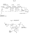
- Fig. 11 is a block schematic diagram.
- a microphone 51 in the arrangement of Fig. 11 converts a vocal sound to an electric signal and outputs a voice signal.
- This voice signal is supplied to a high-pass filter 58 and a low-pass filter 59 via a preamplifier circuit 52, respectively.
- the high-pass filter 58 is designed so as to pass signals at a frequency of 150 Hz or higher.
- the low-pass filter 59 is designed so as to pass low frequency signals containing a main factor of wind noise at a frequency of 150 Hz or lower.
- An output signal of the high-pass filter 58 is supplied to an input terminal of an adder circuit 61.
- An output signal of the low-pass filter 59 is supplied to another input terminal of the adder circuit 61 via an automatic level control circuit 60.
- the automatic level control circuit 60 supplies the output signal of the low-pass filter 59 to the input side of a variable gain amplifier circuit 60a, and results in the variable gain amplifier circuit 60a supplying its output signal to another input terminal of the adder circuit 61.
- the automatic level control circuit 60 supplies the output signal of the variable gain amplifier circuit 60a to a level detection circuit 60b, and reduces the gain of the variable gain amplifier circuit 60a in accordance with a detection level determined by the level detection circuit 60b.
- the automatic level control circuit 60 is designed so as to have no attenuation in the absence of wind noise and an increase in the level of attenuation as the wind noises level increases.
- the first example of the prior art has some problems such as a complex electric circuit construction and an unnatural feeling whilst talking caused by the alteration of the speaker's voice quality due to an alteration in the frequency response when the wind noise prevention function is ON.
- Fig. 12 shows a side view of a handset partly broken away.
- Fig. 13 represents a fragmentary view taken in the direction of an arrow in Fig. 12.
- a protuberant telephone mouthpiece surface 76 has a dome-like shape with its top positioned at the centre of a telephone mouth-piece unit 73 connected to a base 72.
- An acoustic perforation 721 is formed slightly apart from the top of the dome-like shaped telephone mouthpiece surface 786 in the direction opposite to a receiver unit 74.
- the acoustic perforation 721 is so formed as to be apart from the receiver unit 74 as it goes from a front air chamber 78 towards the telephone mouthpiece surface 76.
- the user When speaking using the above hand-set 71, the user usually has his/her ear tightly pressed to the receiver unit 74 for catching the other speaker's voice through an electrodynamic receiver 75.
- the cheek of the speaker is in close contact with the surface of the base 72.
- the user's lips are also located too close to the side of the protuberant domed-shaped telephone mouthpiece unit 73 in the direction of the receiver unit 74.
- the opening section of the acoustic perforation 721 located apart from the top of the telephone mouthpiece surface 76 in the direction towards the receiver unit 74.
- the acoustic perforation 721 is so formed as to be apart from the receiver unit 74 as is the front air chamber 78 apart from the telephone mouthpiece surface 76.
- This construction serves to minimise the possibility of wind entering into the acoustic perforation 721 directly, thus suppressing turbulence occurring therein and reducing noise. Since the space between the speaker's lips and the acoustic perforation 721 is remarkably small, the vocal sound itself becomes almost non-directional, resulting in little degradation in the voice signal.
- the first prior proposed arrangement requires no additional parts or major design modification, reducing the wind noise at a minimum cost.
- the second prior example reduces the effect of the breathing noises of the talker.
- its ability to suppress noise due to turbulence from outside is hardly improved, because it is arranged to cope with the air flow in a certain direction only.
- wind noise may be reduced, even out of doors, and that resonance due to wind noise in the acoustic duct section of a telephone mouthpiece may be reduced.
- a telephone mouthpiece to be described below includes an acoustic duct box provided with an acoustic perforation, a microphone unit provided on a surface of the acoustic duct box facing to another surface of the acoustic duct box having the acoustic perforation, a plurality of partitions provided within the acoustic duct box, and a plurality of slits respectively provided in the partitions.
- P A is an acoustic pressure caused by a speaker
- P B is an acoustic pressure caused by wind noises at an acoustic perforation 1.
- L is a distance where a voice of the speaker passes until reaching to the acoustic perforation 1
- R is an acoustic resistance.
- 1 and 1' are acoustic duct distances between the acoustic perforation 1 and a microphone unit 2, respectively
- r and r' are resistances of distance 1 and distance 1', respectively.
- L is in centimetres and 1 is in millimetres, so the relation between R and r is R>r.
- Attenuation ratios of the generated acoustic pressure P A and the wind noise pressure P B are compared in the cases in which the acoustic duct distances are 1 and 1'.
- the generated acoustic pressure P A is reduced 20% than the case that the acoustic duct distance is 1.
- the wind noise acoustic pressure P B is reduced 50% compared to the case in which the acoustic duct distance is 1.
- the acoustic duct is partitioned by slit partitions.
- air chambers formed by the partitions serve to increase the attenuation of the wind noise acoustic pressure to the microphone greater than that of the generated acoustic pressure of a speaker.
- the present invention enables the effect of wind noise to be reduced without causing a deterioration in the sound quality of a speaker.
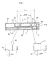
- Fig. 3 is an exploded view showing a part of a hand held portable phone mounted in conjunction with an embodiment of the present invention
- Fig. 4 is a cross section view on A-A in Fig. 3
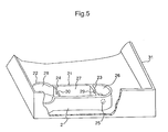
- Fig. 5 is a view showing a reversed upper enclosure of the hand held portable phone of Fig. 3.
- the telephone mouthpiece includes a unit housing section 1, an acoustic duct section 2 which is tightly fitted thereto and which has been integrally formed with an upper enclosure 31 of the hand held portable phone and a microphone unit 3 connected to an electronic circuit base 33 within the hand held portable phone.
- the unit housing section 1 formed of a rubber member has a cylindrical housing 12 for housing the microphone unit 3 at one end of a flat plate 11.
- a protrusion 13 is provided at the other end of the flat plate 11 to be positioned and fixed into a hole 34 formed in the electronic circuit base 33.
- the reason for forming the unit housing section 1 of a rubber member is to increase air tightness with the acoustic duct section 2 and to prevent a leak of the sound.
- the acoustic duct section 2 includes an acoustic duct box 21 in the form of a box in close contact with the corresponding flat plate 11, and a cylindrical box 22 in close contact with the cylindrical housing 12 at an end of the acoustic duct box 21.
- the acoustic duct box 21 includes an acoustic perforation 25 at the other end of the acoustic duct box 21 and on a surface opposite to the surface facing the flat plate 11, and partitions 23 and 24 for partitioning the inside of the acoustic duct box 21 into two air chambers 26 and 27.
- the partitions 23 and 24 are provided with slots or slits 29 and 30, respectively.
- the unit housing section 1 and the acoustic duct section 2 forming the telephone mouthpiece of the present embodiment are disposed between the upper enclosure 31 and a lower enclosure 32.
- the length of the acoustic duct is 15mm
- the distance between the partitions 23 and 24 is 10mm
- the length of a side of a slot or slit 29 is 1.0 mm
- the length of one side of the slot or slit 30 is 0.25 mm.
- Fig. 6 shows comparison data of wind noises of the embodiment constructed as above and illustrating the invention and a conventional telephone mouthpiece which does not have a substantial acoustic duct, but which has a microphone closely touching an acoustic perforation.
- the telephone mouthpiece of the present embodiment acts to reduce wind noise more than the conventional telephone mouthpiece.
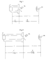
- Fig. 7 shows an acoustic duct model employing primary resonance
- Fig. 8 shows an equivalent circuit of the acoustic duct model of Fig. 7.
- D is the diameter of an acoustic perforation
- t is the thickness of a wall of an acoustically perforated section
- V is the volume of an acoustic duct.
- D 0.8 mm
- t 0.8 mm
- V 130 mm3.
- an acoustic perforation (slit or slot) can be substituted by a coil L and a resistor R1.
- a volume, a length of an acoustic duct and a microphone can be substituted by a capacitor C, a resistor R0 and a resistor R2, respectively.
- the units are in mm, 344000 is the speed of sound, ⁇ 0 is the angular speed at the point of resonance, and Q represents the sharpness of the resonance.
- R 1 0.1 ⁇
- L 2(0.8 + 0.15 ⁇ 0.8)/344000 ⁇ 0.8 2 ⁇ 3.14 ⁇ 4.0[H].
- D is calculated by substituting the area of a circular slot or slit by an equivalent area.
- D of the slot or slit 29 of the present arrangement is 1.1 mm approximately, and D for the slot or slit 30 is 0.28 mm approximately.
- R ⁇ t/s is known.
- s is an area of a cross section of the acoustic perforation (slot or slit).
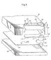
- Fig. 10 an equivalent circuit of the present arrangement can be calculated, resulting in the circuit of Fig. 10.
- the acoustic perforation 25 is replaced by a series circuit of a coil L1 and a resistor R1.
- a slit 29 is replaced by a series circuit of a coil L2 and a resistor R2.
- a slit 30 is replaced by a series circuit of a coil L3 and a resistor R3.
- Air chambers 26, 27 and 28 are replaced by capacitors C1, C2 and C3, respectively.
- the microphone unit 3 is replaced by a resistor R4.
- the length of the acoustic duct is substituted by R0.
- the acoustic duct section 2 as a whole is equivalent to a multi-staged low pass filter.
- Simulation based on the equivalent circuit shown in Fig. 7 enables the values to be varied of the distance between the partition 23 and the partition 24 (the positions of air chambers 26, 27 and 28), and of the sizes of the slots or slits 29 and 30 to values other than those of the particular arrangement described.
Landscapes
- Engineering & Computer Science (AREA)
- Signal Processing (AREA)
- Telephone Set Structure (AREA)
Applications Claiming Priority (3)
| Application Number | Priority Date | Filing Date | Title |
|---|---|---|---|
| JP246109/94 | 1994-10-12 | ||
| JP24610994 | 1994-10-12 | ||
| JP6246109A JP2609822B2 (ja) | 1994-10-12 | 1994-10-12 | 送話器 |
Publications (3)
| Publication Number | Publication Date |
|---|---|
| EP0707403A2 true EP0707403A2 (fr) | 1996-04-17 |
| EP0707403A3 EP0707403A3 (fr) | 1998-03-18 |
| EP0707403B1 EP0707403B1 (fr) | 2004-09-22 |
Family
ID=17143623
Family Applications (1)
| Application Number | Title | Priority Date | Filing Date |
|---|---|---|---|
| EP95307149A Expired - Lifetime EP0707403B1 (fr) | 1994-10-12 | 1995-10-10 | Microphone pour combiné téléphonique et méthode de réduction du bruit du souffle |
Country Status (4)
| Country | Link |
|---|---|
| US (1) | US5701354A (fr) |
| EP (1) | EP0707403B1 (fr) |
| JP (1) | JP2609822B2 (fr) |
| AU (1) | AU708292B2 (fr) |
Cited By (5)
| Publication number | Priority date | Publication date | Assignee | Title |
|---|---|---|---|---|
| WO1997042745A1 (fr) * | 1996-05-03 | 1997-11-13 | Telefonaktiebolaget Lm Ericsson (Publ) | Micro pour appareil de communication vocale |
| GB2315633A (en) * | 1996-07-19 | 1998-02-04 | Nec Corp | Acoustic resistance cloth filling channel between microphone and off-set sound port improves wind screening |
| EP1780989A1 (fr) * | 2005-10-26 | 2007-05-02 | Research In Motion Limited | Coupleur de microphone pour un dispositif de communication |
| US7555118B2 (en) | 2005-10-26 | 2009-06-30 | Research In Motion Limited | Microphone coupler for a communication device |
| CN101742371A (zh) * | 2008-11-12 | 2010-06-16 | 潍坊歌尔电子有限公司 | 一种抑制风噪声的麦克风 |
Families Citing this family (23)
| Publication number | Priority date | Publication date | Assignee | Title |
|---|---|---|---|---|
| US5890072A (en) * | 1996-11-07 | 1999-03-30 | Ericsson, Inc. | Radiotelephone having a non-resonant wave guide acoustically coupled to a microphone |
| US6038328A (en) * | 1997-07-07 | 2000-03-14 | Hughes Electronics Corporation | Minimization of acoustic echo effects in a microphone boot |
| US6101402A (en) * | 1997-09-04 | 2000-08-08 | Ericcson Inc. | Radiotelephone with sliding acoustic member |
| GB2333004B (en) | 1997-12-31 | 2002-03-27 | Nokia Mobile Phones Ltd | Earpiece acoustics |
| JP4000217B2 (ja) * | 1998-05-15 | 2007-10-31 | 株式会社オーディオテクニカ | マイクロホン |
| JP4258225B2 (ja) * | 2003-02-14 | 2009-04-30 | トヨタ自動車株式会社 | 車両の位置検出装置及び方法 |
| US20060147060A1 (en) * | 2004-12-30 | 2006-07-06 | Plantronics, Inc. A Delaware Corporation | Multifunction preamplifier microphone |
| US20080159558A1 (en) * | 2006-12-28 | 2008-07-03 | Fortemedia, Inc. | Internal microphone array or microphone module not affecting appearance of electronic device |
| US8126138B2 (en) | 2007-01-05 | 2012-02-28 | Apple Inc. | Integrated speaker assembly for personal media device |
| US8306252B2 (en) * | 2007-01-05 | 2012-11-06 | Apple Inc. | Integrated microphone assembly for personal media device |
| JP4762927B2 (ja) * | 2007-02-01 | 2011-08-31 | 富士通株式会社 | 電子機器、電子機器の製造方法、及び携帯端末装置 |
| JP4924074B2 (ja) * | 2007-02-09 | 2012-04-25 | 日本電気株式会社 | 電子機器におけるマイクロホンの実装構造及び電子機器 |
| US8351633B2 (en) * | 2008-09-17 | 2013-01-08 | Teodoro Lassally | Noise cancelling microphone with wind shield |
| USD603848S1 (en) | 2008-11-24 | 2009-11-10 | Speedcom Communication, Inc. | Noise cancelling microphone |
| WO2010068961A1 (fr) * | 2008-12-15 | 2010-06-24 | Blueant Wireless Pty Limited | Dispositif audio |
| US8290546B2 (en) | 2009-02-23 | 2012-10-16 | Apple Inc. | Audio jack with included microphone |
| CN102835133B (zh) * | 2010-04-06 | 2015-12-02 | 唯听助听器公司 | 适于风噪声抑制的助听器 |
| WO2020051786A1 (fr) * | 2018-09-12 | 2020-03-19 | Shenzhen Voxtech Co., Ltd. | Dispositif de traitement de signal comprenant de multiples transducteurs électroacoustiques |
| US9066172B2 (en) | 2012-09-28 | 2015-06-23 | Apple Inc. | Acoustic waveguide and computing devices using same |
| US9380369B2 (en) | 2013-02-14 | 2016-06-28 | Apple Inc. | Microphone seal |
| CN114677996A (zh) * | 2020-12-25 | 2022-06-28 | 华为技术有限公司 | 防风噪设备及设计方法 |
| US12225146B2 (en) | 2021-03-02 | 2025-02-11 | Apple Inc. | Acoustic module for handheld electronic device |
| CN216599960U (zh) * | 2021-09-27 | 2022-05-24 | 北京罗克维尔斯科技有限公司 | 车载麦克风及车辆 |
Citations (2)
| Publication number | Priority date | Publication date | Assignee | Title |
|---|---|---|---|---|
| JPH01139649A (ja) | 1987-11-27 | 1989-06-01 | Toshiba Corp | 金型清掃体及び金型清掃方法 |
| JPH02214400A (ja) | 1989-02-15 | 1990-08-27 | Sony Corp | マイクロホン装置 |
Family Cites Families (16)
| Publication number | Priority date | Publication date | Assignee | Title |
|---|---|---|---|---|
| US1419606A (en) * | 1922-01-27 | 1922-06-13 | Jack Dietrich | Telephone muffler |
| GB732243A (en) * | 1952-09-10 | 1955-06-22 | Isaac Levin | Improvements in or relating to telephone mouthpieces |
| US3553374A (en) * | 1969-03-20 | 1971-01-05 | Digitronics Corp | Acoustic coupler |
| US3796842A (en) * | 1972-07-20 | 1974-03-12 | E Guille | Dictation mask |
| JPS6017191B2 (ja) * | 1977-12-30 | 1985-05-01 | アイホン株式会社 | 風雑音減衰効果を有するマイクロンホンユニツト |
| ATA74486A (de) * | 1986-03-20 | 1987-04-15 | Akg Akustische Kino Geraete | Richtmikrophon nach dem elektrostatischen oder elektrodynamischen wandlerprinzip |
| JPH0727715Y2 (ja) * | 1989-02-06 | 1995-06-21 | 株式会社東芝 | ハンドセット |
| US5239578A (en) * | 1990-05-15 | 1993-08-24 | Plantronics, Inc. | Noise cancelling apparatus for a telephone handset |
| US5282245A (en) * | 1990-08-13 | 1994-01-25 | Shure Brothers, Incorporated | Tubular bi-directional microphone with flared entries |
| DE69232313T2 (de) * | 1992-05-11 | 2002-06-20 | Jabra Corp., San Diego | Unidirektionales ohrmikrophon und verfahren dafür |
| US5288955A (en) * | 1992-06-05 | 1994-02-22 | Motorola, Inc. | Wind noise and vibration noise reducing microphone |
| US5343523A (en) * | 1992-08-03 | 1994-08-30 | At&T Bell Laboratories | Telephone headset structure for reducing ambient noise |
| TW274675B (fr) * | 1992-09-08 | 1996-04-21 | Motorola Inc | |
| CA2101500C (fr) * | 1992-09-30 | 1996-12-17 | Charles Spurgeon Bartlett | Combine telephonique a l'elimination de bruit ambiant |
| US5448637A (en) * | 1992-10-20 | 1995-09-05 | Pan Communications, Inc. | Two-way communications earset |
| JP2626534B2 (ja) * | 1993-12-28 | 1997-07-02 | 日本電気株式会社 | 電子機器の送話部構造 |
-
1994
- 1994-10-12 JP JP6246109A patent/JP2609822B2/ja not_active Expired - Fee Related
-
1995
- 1995-10-10 US US08/541,411 patent/US5701354A/en not_active Expired - Lifetime
- 1995-10-10 EP EP95307149A patent/EP0707403B1/fr not_active Expired - Lifetime
- 1995-10-11 AU AU33185/95A patent/AU708292B2/en not_active Ceased
Patent Citations (2)
| Publication number | Priority date | Publication date | Assignee | Title |
|---|---|---|---|---|
| JPH01139649A (ja) | 1987-11-27 | 1989-06-01 | Toshiba Corp | 金型清掃体及び金型清掃方法 |
| JPH02214400A (ja) | 1989-02-15 | 1990-08-27 | Sony Corp | マイクロホン装置 |
Cited By (11)
| Publication number | Priority date | Publication date | Assignee | Title |
|---|---|---|---|---|
| WO1997042745A1 (fr) * | 1996-05-03 | 1997-11-13 | Telefonaktiebolaget Lm Ericsson (Publ) | Micro pour appareil de communication vocale |
| US5913178A (en) * | 1996-05-03 | 1999-06-15 | Telefonaktiebolaget Lm Ericsson | Microphone in a speech communicator |
| GB2315633A (en) * | 1996-07-19 | 1998-02-04 | Nec Corp | Acoustic resistance cloth filling channel between microphone and off-set sound port improves wind screening |
| US6091830A (en) * | 1996-07-19 | 2000-07-18 | Nec Corporation | Transmitter structure for limiting the effects of wind noise on a microphone |
| GB2315633B (en) * | 1996-07-19 | 2000-12-20 | Nec Corp | Transmitter structure |
| EP1780989A1 (fr) * | 2005-10-26 | 2007-05-02 | Research In Motion Limited | Coupleur de microphone pour un dispositif de communication |
| US7555118B2 (en) | 2005-10-26 | 2009-06-30 | Research In Motion Limited | Microphone coupler for a communication device |
| EP2244445A1 (fr) * | 2005-10-26 | 2010-10-27 | Research In Motion Limited | Coupleur de microphone pour un dispositif de communication |
| US8005207B2 (en) | 2005-10-26 | 2011-08-23 | Research In Motion Limited | Microphone coupler system for a communication device |
| US8488777B2 (en) | 2005-10-26 | 2013-07-16 | Research In Motion Limited | Microphone coupler system for a communication device |
| CN101742371A (zh) * | 2008-11-12 | 2010-06-16 | 潍坊歌尔电子有限公司 | 一种抑制风噪声的麦克风 |
Also Published As
| Publication number | Publication date |
|---|---|
| AU708292B2 (en) | 1999-07-29 |
| US5701354A (en) | 1997-12-23 |
| JPH08111705A (ja) | 1996-04-30 |
| JP2609822B2 (ja) | 1997-05-14 |
| AU3318595A (en) | 1996-04-26 |
| EP0707403B1 (fr) | 2004-09-22 |
| EP0707403A3 (fr) | 1998-03-18 |
Similar Documents
| Publication | Publication Date | Title |
|---|---|---|
| EP0707403B1 (fr) | Microphone pour combiné téléphonique et méthode de réduction du bruit du souffle | |
| US6091830A (en) | Transmitter structure for limiting the effects of wind noise on a microphone | |
| US4160135A (en) | Closed earphone construction | |
| US5282245A (en) | Tubular bi-directional microphone with flared entries | |
| US6321070B1 (en) | Portable electronic device with a speaker assembly | |
| US6785395B1 (en) | Speaker configuration for a portable electronic device | |
| US5473684A (en) | Noise-canceling differential microphone assembly | |
| US6134336A (en) | Integrated speaker assembly of a portable electronic device | |
| US5896461A (en) | Compact speakerphone apparatus | |
| US6058315A (en) | Speaker assembly for a radiotelephone | |
| US6272360B1 (en) | Remotely installed transmitter and a hands-free two-way voice terminal device using same | |
| EP0661902A1 (fr) | Dispositif d'élimination de bruit dans un microphone | |
| US7260236B2 (en) | Wind noise suppression in directional microphones | |
| EP3021560B1 (fr) | Cavité arrière de haut-parleur | |
| EP0364935B1 (fr) | Transducteur téléphonique | |
| JP2859527B2 (ja) | ラウドスピーカ組立体 | |
| CN112437379A (zh) | 入耳式耳机 | |
| GB2064265A (en) | Microphone unit | |
| US6421444B1 (en) | Embedded higher order microphone | |
| EP1074168B1 (fr) | Telephone dote d'un moyen d'amelioration de la reponse basse frequence | |
| CN102918871A (zh) | 适于风噪声抑制的助听器 | |
| JP2590651B2 (ja) | マイクロホンユニットの取付構造 | |
| CN214315557U (zh) | 一种带分流通道的电容咪芯 | |
| JP2548062Y2 (ja) | 送話器構造 | |
| EP0469955A2 (fr) | Combiné émetteur récepteur |
Legal Events
| Date | Code | Title | Description |
|---|---|---|---|
| PUAI | Public reference made under article 153(3) epc to a published international application that has entered the european phase |
Free format text: ORIGINAL CODE: 0009012 |
|
| AK | Designated contracting states |
Kind code of ref document: A2 Designated state(s): GB IT |
|
| PUAL | Search report despatched |
Free format text: ORIGINAL CODE: 0009013 |
|
| AK | Designated contracting states |
Kind code of ref document: A3 Designated state(s): GB IT |
|
| 17P | Request for examination filed |
Effective date: 19980218 |
|
| 17Q | First examination report despatched |
Effective date: 20020716 |
|
| GRAP | Despatch of communication of intention to grant a patent |
Free format text: ORIGINAL CODE: EPIDOSNIGR1 |
|
| GRAS | Grant fee paid |
Free format text: ORIGINAL CODE: EPIDOSNIGR3 |
|
| GRAA | (expected) grant |
Free format text: ORIGINAL CODE: 0009210 |
|
| AK | Designated contracting states |
Kind code of ref document: B1 Designated state(s): GB IT |
|
| REG | Reference to a national code |
Ref country code: GB Ref legal event code: FG4D |
|
| PLBE | No opposition filed within time limit |
Free format text: ORIGINAL CODE: 0009261 |
|
| STAA | Information on the status of an ep patent application or granted ep patent |
Free format text: STATUS: NO OPPOSITION FILED WITHIN TIME LIMIT |
|
| 26N | No opposition filed |
Effective date: 20050623 |
|
| PGFP | Annual fee paid to national office [announced via postgrant information from national office to epo] |
Ref country code: IT Payment date: 20091016 Year of fee payment: 15 Ref country code: GB Payment date: 20091007 Year of fee payment: 15 |
|
| GBPC | Gb: european patent ceased through non-payment of renewal fee |
Effective date: 20101010 |
|
| PG25 | Lapsed in a contracting state [announced via postgrant information from national office to epo] |
Ref country code: GB Free format text: LAPSE BECAUSE OF NON-PAYMENT OF DUE FEES Effective date: 20101010 |
|
| PG25 | Lapsed in a contracting state [announced via postgrant information from national office to epo] |
Ref country code: IT Free format text: LAPSE BECAUSE OF NON-PAYMENT OF DUE FEES Effective date: 20101010 |