EP0707411A2 - Verbessertes Verfahren und Gerät zur Erzeugung von Zittermatrizen zur Herabsetzung von Artefakten in Halbtonbilddaten unter Verwendung von Tintenverminderungsverarbeitung - Google Patents
Verbessertes Verfahren und Gerät zur Erzeugung von Zittermatrizen zur Herabsetzung von Artefakten in Halbtonbilddaten unter Verwendung von Tintenverminderungsverarbeitung Download PDFInfo
- Publication number
- EP0707411A2 EP0707411A2 EP95307164A EP95307164A EP0707411A2 EP 0707411 A2 EP0707411 A2 EP 0707411A2 EP 95307164 A EP95307164 A EP 95307164A EP 95307164 A EP95307164 A EP 95307164A EP 0707411 A2 EP0707411 A2 EP 0707411A2
- Authority
- EP
- European Patent Office
- Prior art keywords
- value
- binary
- pattern
- pixels
- pixel
- Prior art date
- Legal status (The legal status is an assumption and is not a legal conclusion. Google has not performed a legal analysis and makes no representation as to the accuracy of the status listed.)
- Granted
Links
- 238000000034 method Methods 0.000 title claims abstract description 147
- 238000012545 processing Methods 0.000 title description 81
- 238000007639 printing Methods 0.000 claims abstract description 65
- 238000009792 diffusion process Methods 0.000 claims abstract description 53
- 230000008569 process Effects 0.000 claims abstract description 40
- 238000012937 correction Methods 0.000 claims abstract description 17
- 239000011800 void material Substances 0.000 claims description 22
- 230000007246 mechanism Effects 0.000 claims description 7
- 238000007781 pre-processing Methods 0.000 abstract description 4
- 230000006870 function Effects 0.000 description 49
- 238000003491 array Methods 0.000 description 22
- 238000010586 diagram Methods 0.000 description 16
- 230000004044 response Effects 0.000 description 9
- 238000013139 quantization Methods 0.000 description 7
- 230000000694 effects Effects 0.000 description 6
- 238000001228 spectrum Methods 0.000 description 6
- 238000012546 transfer Methods 0.000 description 6
- 230000000007 visual effect Effects 0.000 description 6
- 238000007796 conventional method Methods 0.000 description 4
- 238000003384 imaging method Methods 0.000 description 4
- 238000013459 approach Methods 0.000 description 3
- 230000001419 dependent effect Effects 0.000 description 3
- 230000006872 improvement Effects 0.000 description 3
- 238000012986 modification Methods 0.000 description 3
- 230000004048 modification Effects 0.000 description 3
- 230000000737 periodic effect Effects 0.000 description 3
- 239000008186 active pharmaceutical agent Substances 0.000 description 2
- WYTGDNHDOZPMIW-RCBQFDQVSA-N alstonine Natural products C1=CC2=C3C=CC=CC3=NC2=C2N1C[C@H]1[C@H](C)OC=C(C(=O)OC)[C@H]1C2 WYTGDNHDOZPMIW-RCBQFDQVSA-N 0.000 description 2
- 230000003190 augmentative effect Effects 0.000 description 2
- 238000006243 chemical reaction Methods 0.000 description 2
- 238000009795 derivation Methods 0.000 description 2
- 238000005516 engineering process Methods 0.000 description 2
- 238000000265 homogenisation Methods 0.000 description 2
- 230000003993 interaction Effects 0.000 description 2
- 241000699670 Mus sp. Species 0.000 description 1
- 241000519995 Stachys sylvatica Species 0.000 description 1
- 230000003044 adaptive effect Effects 0.000 description 1
- 238000000149 argon plasma sintering Methods 0.000 description 1
- 239000003086 colorant Substances 0.000 description 1
- 238000007906 compression Methods 0.000 description 1
- 230000006835 compression Effects 0.000 description 1
- 238000010276 construction Methods 0.000 description 1
- 230000003247 decreasing effect Effects 0.000 description 1
- 238000001739 density measurement Methods 0.000 description 1
- 238000013461 design Methods 0.000 description 1
- 230000009977 dual effect Effects 0.000 description 1
- 238000009472 formulation Methods 0.000 description 1
- 239000011159 matrix material Substances 0.000 description 1
- 230000003278 mimic effect Effects 0.000 description 1
- 239000000203 mixture Substances 0.000 description 1
- 230000002093 peripheral effect Effects 0.000 description 1
- 230000003252 repetitive effect Effects 0.000 description 1
- 238000005070 sampling Methods 0.000 description 1
- 238000012216 screening Methods 0.000 description 1
- 239000007787 solid Substances 0.000 description 1
- 230000016776 visual perception Effects 0.000 description 1
Images






Classifications
-
- H—ELECTRICITY
- H04—ELECTRIC COMMUNICATION TECHNIQUE
- H04N—PICTORIAL COMMUNICATION, e.g. TELEVISION
- H04N1/00—Scanning, transmission or reproduction of documents or the like, e.g. facsimile transmission; Details thereof
- H04N1/40—Picture signal circuits
- H04N1/405—Halftoning, i.e. converting the picture signal of a continuous-tone original into a corresponding signal showing only two levels
- H04N1/4051—Halftoning, i.e. converting the picture signal of a continuous-tone original into a corresponding signal showing only two levels producing a dispersed dots halftone pattern, the dots having substantially the same size
Definitions
- the present invention relates to digital image processing, and more particularly, but not exclusively, to a technique for reducing the amount of ink and processing time required for printing.
- Pictorial images such as those produced by photographic techniques or by computerised imaging systems, by contrast are continuous in tonality. If such an image is divided into pixels, each pixel exhibits a "grayscale” colour whose tonal value falls within a range of tonal values, in order to reproduce such "continuous-tone" images by means of electronic printing, the images must therefore be converted into a form which is suited to the characteristics of the printing device, generally a binary format.
- This conversion process which may take many forms, is generically referred to as "halftoning".
- halftone image actually consists solely of a spatial pattern of binary pixels (coloured or blank dots), the human visual system integrates this pattern to create an illusion of a continuous-tone image.
- the image to be printed is divided into a series of pixels and the value of the image in each pixel is quantized to produce a multi-bit digital word which represents the tonal value of the pixel.
- the image is thus converted to a stream of digital words which are provided to the printing device.
- halftoning is performed on the digital word stream during a process called "preprocessing".
- preprocessing Numerous halftoning techniques have been developed and refined over the years. In their simplest form, such techniques compare the value of each digital word with a threshold level, and generate a binary output pixel value depending on the relative values.
- a digital scanner processing a continuous-tone image might generate a stream of multi-bit words representing the detected light intensities. Commonly, the numerical value of these words ranges from 0 to 255, corresponding to a 256-level gray scale or an eightbit word. If such a digital word stream is to be reproduced on a binary printing device, the halftoning process compares the scanner output words with a either a single threshold value or an array of threshold values to produce the required binary output pixel stream. In such a system, each 8-bit scanner word has effectively been compressed into a single-bit output word.
- error diffusion attempts to "diffuse” the "quantization error” (i.e., the difference between the input value represented by a multi-bit word and the output value represented by a single bit or two multi-bit words) proportionally among neighboring pixels.
- This diffusion is performed by adding a portion of the quantization error to the input values of the next pixel in the processing line and to neighboring pixels in the following line or lines.
- the quantization error is added to the pixel values before processing so that the quantization error is "spread" over several pixels.
- the input pixels represented by the input words are processed in "raster" order (line-by-line with each line being processed from left to right before the next lower line is processed).
- the error diffusion process produces an excellent image reproduction, but also creates well-known artifacts called "worms” and "snowplowing” which degrade image quality.
- the "worms” appear as curved or straight diagonal lines in areas of uniform gray and produce a patterned appearance in the halftoned image. Consequently, various techniques have been used to reduce or eliminate these kinds of artifact patterns.
- Another known method, described in Japanese Laid-Open Patent HEI 3-151762/91, of minimizing the appearance of worms also varies the processing sequence from the conventional raster pattern.
- the processing direction for each image line is selected based on the output of a random number generator or noise pattern generator which is quantized to yield a stream of "1's" and "0's". Pixel processing for each line is therefore performed left-to-right (in response to a "1") or right-to-left (in response to a "0") in a random pattern.
- pixels in image lines are processed left-to-right and right-to-left in predetermined periodic patterns, e.g., two left-to-right scans, followed by two right-to-left scans, and so on. While these prior processing order techniques reduce the size of the worms, the worms are still visible in the halftoned image.
- Another problem inherent in the error-diffusion method is the large number of computations necessary to process an image. Since several computations, including multiplications, must be performed on each processed pixel, millions of computations may be necessary to generate the final output values for a typical high-resolution image. In addition, it is necessary to store at least one line of error values that are to be applied to the succeeding line of image values. This large number of computations and the required storage combine to increase the processing time for each image, resulting in decreased printer throughput.
- dithering in which an array of predetermined (and generally different) threshold values -- a "dither array” -- with the same spacing as the image pixels is conceptually overlaid onto the image pixel array. If the dither array is smaller than the image array, then the dither array is repeated side-by-side or "tiled over the image array to produce a repetitive pattern. Each pixel thus has two values conceptually associated with it, namely, the actual pixel tonal value and the threshold value of the overlaid dither array cell to which it is compared.
- the values in the dither array can be added to the tonal value of each pixel, and the augmented value compared with a fixed threshold. In either case, an output value is generated based on the comparison. Since the processing of each pixel involves only a simple comparison and is independent of neighboring pixel values, the computation time required to process an entire image is substantially less than that required for error diffusion.
- the quality of the resulting processed image depends entirely on the threshold values chosen for the dither array.
- Two types of dither arrays are commonly used. In a "clustered-dot" dither array, the threshold values are organized into small groups having closely spaced values. These clusters mimic “dots" of various sizes, and thus produce processed images visually similar to those produced by the traditional halftone screen used for many years in photoengraving processes.
- dispersed-dot dithering In “dispersed-dot” dithering, large and small threshold values are spread even throughout the array. This technique enhances the printable gray scale as well as resolution.
- the dispersed-dot dither array usually produces better image quality than the clustered-dot dither array; this is because dispersed-dot arrays achieve better high-frequency fidelity and create a better illusion of a continuous gray region than do clustered-dot arrays of the same resolution and period.
- recursive tessellation One common technique used to create a homogenous ordered dither array is called “recursive tessellation".
- the goal of recursive tessellation is to assign threshold values to each of the dither array cells in such a way that, as each successive cell is numbered or "turned on", the two-dimensional array of "on" cells is as homogeneously arranged as possible.
- the dither array is used as a threshold array in a halftoning process, the corresponding arrangement of output binary dots will be disbursed as homogeneously as possible for each gray level to be simulated.
- the algorithm used in recursive tessellation for generating the threshold array is based on the fact that if a regular geometric shape or "tile" is used cover or tessellate the two-dimensional dither array, the center point of the shape and its vertices can serve as center points for a retessellation of the array with new tiles of the same geometric shape but sized one cell smaller. In turn, the center points and vertices of these new tiles can act as center points for another retessellation with tiles that are again one cell smaller.
- all of the tile vertices at each stage of this recursive tessellation are assigned threshold numbers before the next tessellation takes place.
- the algorithm provides a mechanism for locating a family of points that are exactly in the center of voids which occur between the vertex points of the tiles. Essentially, new points are added in the largest "voids" or areas where there is an absence of "on” pixels.
- the recursive tessellation method and the resulting threshold arrays are described in detail in "Digital Halftoning" by Robert Ulichney, printed by the MIT Press, Cambridge, Massachusetts and London, England ,1990, pages 128-171. While the recursive tessellation method can produce large dither arrays, these arrays suffer from a strong periodic structure that imparts an unnatural appearance to the resulting images when the arrays are used in a conventional halftoning operation.
- blue noise is the high-frequency portion of a white noise spectrum.
- the power spectrum of blue noise has a low-frequency cutoff and is flat out to some fine high frequency limit.
- the dot patterns produced by a blue noise mask are aperiodic and radially symmetric and these patterns produce an aperiodic, uncorrelated dither array structure without low frequency graininess.
- the choice of a blue noise mask arose from studies of the frequencies present in dot patterns produced by the error diffusion process described previously. When these dot patterns are converted into to a power spectrum of power versus frequency, it can be seen that the power spectrum has a low frequency cutoff point which occurs in the blue light frequency range, hence the name "blue noise”
- the shape of the power spectrum can be used to construct dither arrays by examining dot patterns which produce blue noise power spectra and creating dither arrays from these dot patterns.
- the resulting arrays produce a high-quality output, however, the conversions between the frequency and spatial domains necessary to derive the arrays produces a complicated algorithm for generating the dither arrays.
- Blue noise masks are described in more detail in " Digital Halftoning Using A Blue Noise Mask ", T. Mitsa and K. Parker, Proceedings SPIE, Image Processing Algorithms And Techniques II, v.1452, pps. 47-56, February 21st - March 1, 1991.
- void-and-cluster method Another conventional technique for generating a large, homogeneous dither array is called the "void-and-cluster method". Again, the goal of this latter method is to produce a homogeneous distribution of 1's and 0's by starting with an initial pattern and removing pixels from the center of the tightest “clusters" and inserting them into the largest "voids”.
- the void-and-cluster method is described in detail in " The Void-and-Cluster Method For Dither Array Generation”, Robert Ulichney, IS&T/SPIE Symposium on Electronic Imaging Science and Technology, San Jose, California, February 3, 1993 and " Filter Design For Void-and-Cluster Dither Arrays ", Robert Ulichney, Society for Information Display International Symposium, San Jose, California, June 14-16, 1994, the contents of which are hereby incorporated by reference.
- the initial pattern used to generate the dither arrays is called a "Prototype Binary Pattern” and the terms “cluster” and “void” are defined in terms of “minority pixels” and “majority pixels”.
- the terms “cluster” and “void” are defined in terms of “minority pixels” and “majority pixels”.
- minority pixels When less than half of the pixels in the Prototype Binary Pattern are of a particular type (either "1's" or "0's") they are denoted as minority pixels and the other type of pixel is denoted as a majority pixel.
- the terms cluster” and “void” refer to the arrangement of minority pixels on a background of majority pixels.
- a "void” is a large space between minority pixels and a “cluster” is a tight grouping of minority pixels.
- minority pixels are always added to the center of the largest voids and are removed (or replaced with a majority pixel) from the center of the tightest cluster in order to homogenize the pattern.
- the void-and-cluster method consists of three distinct steps:
- the Prototype Binary Pattern is generated by using any convenient technique that generates an input pattern where not more than half the pixels are "1's" and the rest are "0's".
- a white noise pattern will serve as the Prototype Binary Pattern.
- the next step in the method is to find the "voids" and the "clusters” so that pixels can be moved between the voids and clusters.
- Voids and clusters are located by means of a filter which examines the neighboring pixels bordering each pixel being processed.
- a void-finding filter considers the neighborhood pixels around every majority pixel in the Prototype Binary Pattern
- a cluster-finding filter considers the neighborhood pixels around every minority pixel.
- a two-dimensional Gaussian filter represented by the function: e - x 2 2 ⁇ x 2 - y 2 2 ⁇ y 2 is used in order to find voids and clusters.
- the values in the array are repeatedly processed and a single pixel may be moved several times from cluster to void. This processing is performed iteratively until the voids stop getting smaller and the clusters stop getting looser. Processing is deemed complete when removing the "1" from the tightest cluster in the pattern creates the largest void.
- the resulting homogenized pattern is called the Initial Binary Pattern.
- the dither array is built from the Initial Binary Pattern by assigning threshold values to the dither array using the Initial Binary Pattern.
- the Initial Binary Pattern and the dither array are manipulated in parallel in three phases in accordance with a predetermined algorithm. Threshold values are assigned to the dither array cells based on the "rank" value of the "1's" in the Initial Binary Pattern.
- one minority pixel or "1" is removed at a time from the Initial Binary Pattern while, in parallel, the rank or the number of minority pixels remaining in the Initial Binary Pattern is entered into the dither array in the location corresponding to the location of the removed "1". In each case, the minority pixel that is removed is the pixel in the center of the tightest cluster.
- the Initial Binary Pattern is again used as the starting basis and one minority pixel (or "1") is inserted at a time into the Initial Binary Pattern while, in parallel, its rank is entered into the dither array.
- the minority pixel that is inserted is done so at the location of a "0" identified as the center of the largest void.
- Phase III the Initial Binary Pattern produced by adding "1's” in Phase II is used as the starting point.
- the meaning of "minority pixel” is reversed from “1" to "0” because there are more 1's than 0's in the Initial Binary Pattern due to "1's” being added in Phase II.
- the Initial Binary Pattern is now filled with more and more l's while the dither array continues to be filled with the rank values.
- a "1" is inserted in the "0" location identified in the tightest cluster of minority pixels.
- the Initial Binary Pattern is filled with all 1's and the dither array is filled with a unique rank value in each element from 0 to the maximum of pixels.
- the void and cluster method produces a dither array that, in turn, generates high-quality halftoned images that are generally artifact-free there is still some tonal distortion and the resulting image can be further improved.
- All digital halftoning techniques assume perfectly square pixels, which fully cover the printable area of the recording medium. If this were truly the case, the printer output density would be directly proportional to the input (scanned) density of the original; the ideal case, as indicated by the 45° line in FIG. 12, occurs when output density precisely matches input density.
- the response of real electronic printing devices is typically nonlinear because such devices do not generate perfectly adjacent, nonoverlapping square dots; instead, they tend to produce dots that are more round than square, and which extend beyond the square boundaries of ideal pixels.
- the function f(x) is defined mathematically through piecewise density measurements and regression, and an inverse (transfer) function, f ⁇ 1(x) , (dotted line) defined as well.
- the latter function when applied to incoming source data, offsets the effects of the printer function, correcting the data so that processing by the halftoning algorithm will produce a printed output whose density characteristics more closely match that of the original.
- predistortion produces printed output superior to unmodified halftoned image data
- correction to the ideal linear response does not necessarily produce the most visually desirable printed copy. This is due to the complex interactions between the human visual system and the patterns produced by halftoning algorithms on a variety of scales. Subjective responses frequently vary with both the halftoning algorithm employed and the degree of predistortion. See, e.g., Trontelj et al., “Optimal Halftoning Algorithm Depends on Printing Resolution,” SID 92 Digest at 749 (1992).
- the present invention is directed toward improving predistortion to enhance the visual appearance of printed output.
- the filter is applied to parameters associated with the halftone processing algorithm rather than to the source data.
- the filter function can be applied to these values such that, when the filtered values are applied in an inverse fashion to source data to produce the raster pattern, that pattern is weighted according to the desired nonlinear output function. This approach can generate considerable savings in processing load, since a single dither array is modified just once but is applied repeatedly to the source data.
- FIG. 6 illustrates a hardcopy output of a printer having a resolution of 1/dpi, where dpi is dots per inch.
- ideal pixels 1001 - 1004 are illustrated as "ON". It is noted, that there are no voids between adjacent pixels.
- pixels are in effect an approximation.
- Actual pixels are represented by dots generally more circular in shape. As is known by one of ordinary skill in the art, the size or radius of these dots is dependent on many factors including, for example, the printing mechanism, the ink and the recording sheet.
- FIG. 7 is an example where the diameter of a dot printed for the pixel is equal to or less than 1/dpi. In other words the radius r is less than 1/( ⁇ 2 dpi). As shown therein, a void 1100 is present between dots representing pixels 1001a and 1002a. Accordingly, when two adjacent pixels are ON there will be portions having voids. This example produces unacceptable results and thus dots having a radius ⁇ 1/( ⁇ 2 dpi) are avoided.
- FIG. 8 is another example in which the radius of a dot representing a pixel is: 1/ ⁇ 2 dpi ⁇ r ⁇ 1/ dpi
- pixels 1001c and 1002c there are no voids between dots of adjacent pixels, for example pixels 1001c and 1002c. However, the dots representing pixels 1001c and 1002c overlap in area 1200.
- FIGS. 9-A and 9-B illustrate another example of a dot representing a pixel having a radius of: / dpi ⁇ r ⁇ 2 /dpi
- FIG. 9-A shows for simplicity every other pixel on every other row. As shown therein every other pixel in the same row, for example, pixels 1001d and 1002d (or column, for example, pixels 1002d and 1003d) overlap. However the dots representing pixels 10001c and 1003c do not overlap.
- FIG. 9-B illustrates every pixels. As shown therein, the dot representing pixel 1004d provides redundant information since the dots representing pixels 1001d and 1002d occupy the area of pixel 1004d. As such, ink used to print pixel 1004d is unnecessary. Moreover, additional computations and printing time are required to print with every adjacent pixel. Typical values at 720 dpi of 1/dpi is 0.0014 inches, r is 0.0015 inches and ⁇ 2 /dpi is .0020 inches.
- FIGS. 10-A and 10-B illustrate the example in which a dot representing a pixel has a radius of: ⁇ 2/dpi ⁇ r
- This example is similar to the example in FIGS. 9-A and 9-B, except the dots representing pixels 1001e and 1003e (referred to as alternate diagonal pixels) also intersect.
- printers generally have a resolution of 300 to 360 dpi
- Printers with higher resolutions may have a resolution of 720 dpi.
- printing at 720 dpi has approximately 4 times the resolution as 360 dpi.
- a one inch square printing area contains 720 ⁇ 720 or 518,400 dots.
- a resolution of 360 dpi has 360 ⁇ 360 or 129,600 dots.
- ink and/or paper to print at 720 dpi the dot size obtainable is: / dpi ⁇ r ⁇ ⁇ 2 /dpi as shown-in FIGS. 9-A and 9-B.
- printing at 720 dpi with this dot size results in printing redundant information and requires additional computation and printing time.
- Another object of the invention is to provide a method and apparatus which overcomes the problems of conventional printers.
- a further object of the present invention is to provide a method and apparatus which prints at a high resolution while requiring less ink than compared to conventional devices and methods.
- An additional object of the present invention is to provide a method and apparatus which prints at a high resolution while requiring less computations than compared to conventional devices and methods.
- a still yet another object of the present invention is to provide a method and apparatus which applies non-linear predistortion processing without the loss of dynamic range.
- Still another object of the invention is to provide such a method which can be implemented relatively easily either in specialized hardware or in existing printer drivers.
- a further object of the present invention is to reduce the tonal distortion produced by halftoning using a dither array generated by the void-and-cluster method.
- An additional object of the present invention is to generate an ordered dispersed-dot dither array of arbitrary size wherein the dots are distributed homogeneously.
- It is a further object of the present invention is to reduce the tonal distortion produced by halftoning using a dither array generated by the void-and-cluster method.
- apparatus for generating a starting pattern for use by a void and cluster dither array generation process for halftone image generation of every other pixel n x m pixel data representing an image, n and m being positive integers, the every other pixels comprising n/2 x m pixels, by a printing device comprising: prototype apparatus for generating a prototype binary pattern comprising a two-dimensional array of k x l elements, each element comprising a number having a constant value, wherein k and l are positive integers and wherein each of the k x l elements is in corresponding relation to only the n/2 x m pixels; first homogenizing apparatus responsive to the prototype binary pattern for applying an error diffusion halftoning process to the prototype binary pattern to generate a starting binary pattern comprising a two-dimensional k x l array of binary numbers having one of a first value and
- apparatus for generating an improved dither array for halftone image generation of every other pixel of n x m pixel data representing an image, n and m being positive integers, the every other pixels comprising n/2 x m pixels, by a printing device, the apparatus comprising: prototype apparatus for generating a prototype binary pattern comprising a two-dimensional array of k x l elements, each element comprising a number having a constant value wherein k and l are positive integers and wherein each of the k x l elements is in corresponding relation to only the n/2 x m pixels; first homogenizing apparatus responsive to the prototype binary pattern for applying an error diffusion halftoning process to the prototype binary pattern to generate a starting binary pattern comprising a two-dimensional k x l array of binary numbers having one of a first value and a second value, and wherein each of the k x l elements is in corresponding relation to only the n/2 x m
- a method and an apparatus for converting a continuous-tone image, represented as an array of electronically encoded n x m pixels comprising n rows of m pixels each specifying a gray-scale value, into a binary raster suitable for electronic printing.
- a series of pixels are identified corresponding to a linear segment of the image.
- the identified pixels comprise, for example, odd ones of the m pixels on corresponding odd ones of the n rows of pixels and even ones of the m pixels on corresponding even rows of the n rows of pixels.
- the identified pixels are processed, in the sequence corresponding to a movement along the segment in the predetermined direction to convert the pixels into binary raster values.
- the identifying and processing of the pixels are repeated until the image has been fully processed.
- an image processing means for converting a continuous-tone image into a binary array suitable for printing comprises a memory means for storing an array of electronically encoded n x m pixels each representing a gray-scale value.
- a reading means reads every other pixel from the memory means.
- a halftoning means is provided for iteratively processing series of pixels read by the reading means each corresponding to a linear segment of the image, in a sequence representative of a movement along the segment in a predetermined direction, so as produced binary rest of values therefrom.
- a printer for printing a continuous-tone image as patterns of monochromatic dots on a print medium comprises a digitizing means responsive to the continuous-tone image for generating a stream of electronically m x n encoded pixel values, each represents a gray scale of a portion of the continuous-tone image.
- a memory means responsive to the stream of electronically encoded pixel values is provided for storing the electronically encoded pixel values in a plurality of linear segments, each linear segment having a start and an end and comprising pixel values that represent contiguous portions of the continuous-tone image.
- a reading means reads every other electronically encoded pixel from the memory means.
- a halftoning means processes each pixel value corresponding to the electronically encoded pixels read by the reading means in each of the plurality of linear segments in a start to end sequence and in an end to start sequence to generate output results.
- a print mechanism responsive to the output results generates the patterns of monochrome dots on the print medium.
- a computer system comprises a memory for storing data and programs.
- a central processing unit responsive to the program stored in the memory is provided for controlling and coordinating the operation of the computer system, and a digitizing means responsive to a continuous-tone image generates a stream of electronically encoded pixels each representing gray scale value of a portion of a the continuous-tone image.
- a memory means responsive to the stream of electronically encoded pixels stores the electronically encoded pixel values in a plurality of linear segments, each linear segment having a start and an end and comprising pixel values that represent contiguous portions of the continuous-tone image.
- a reading means reads every other pixel from the memory means.
- a halftoning means processes each pixel value corresponding to the electronically encoded pixel read by the reading means in each of the plurality of line segments in a start to end sequence and an end to start sequence to generate output results.
- a printer responsive to the output results prints patterns of monochrome dots on a print medium to generate a half-tone image.
- an apparatus and a method for printing in which the series of pixel data corresponding to a linear segment of source image is obtained. Every other one of the pixel data obtained is selected. The selected pixel data is filtered in accordance with the filter function. The filtered pixel data is processed into a halftone pattern which, when printed exhibits a density pattern lighter than the source image and highlight in upper midtone regions and darker than that of the source image in shadow in lower midtone regions. The half-tone pattern is printed onto a recording medium.
- a printer comprises a source of serially encoded pixel data representative of density levels associated with the source image.
- a selector selects every other one of the pixel data.
- a half-tone engine processes the selected pixel data into a raster pattern represented of the density pattern corresponding to the source image but lighter than that of the source image in highlight regions and darker than that of the source region in mid-tone and shadow regions.
- a means is provided for applying ink or toner to a recording medium in accordance with the half-tone pattern.
- the inventive method can be incorporated easily into the driver software of a printing device at relatively little cost or embodied in specialized hardware in the printer port or the printer itself.
- high-quality halftone images can be produced by means of error diffusion halftoning with minimized worm-type artifacts.
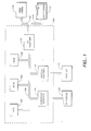
- FIG. 1 illustrates a typical hardware configuration of a computer 100 in accordance with the subject invention.
- the computer 100 is controlled by a central processing unit 102, which may be a conventional microprocessor; a number of other units, all interconnected via a system bus 108, are provided to accomplish specific tasks.
- a particular computer may only have some of the units illustrated in FIG. 1 or may have additional components not shown, most computers will include at least the units shown.
- computer 100 shown in FIG. 1 includes a random access memory (RAM) 106 for temporary storage of information, a read only memory (ROM) 104 for permanent storage of the computer's configuration and basic operating commands and an input/output (I/O) adapter 110 for connecting peripheral devices such as a disk unit 113 and printer 114 to the bus 108, via cables 115 and 112, respectively.
- a user interface adapter 116 is also provided for connecting input devices, such as a keyboard 120, and other known interface devices including mice, speakers and microphones to the bus 108.
- Visual output is provided by a display adapter 118 which connects the bus 108 to a display device 122 such as a video monitor.
- the workstation has resident thereon, and is controlled and coordinated by, an operating system.
- a computer system such as that shown in FIG. 1 generally includes a printing device which is electrically connected to the computer system and controlled by it in order to generate a permanent image on a selected medium.
- a printing device which is electrically connected to the computer system and controlled by it in order to generate a permanent image on a selected medium.
- the print medium generally has a fixed size
- the printable information must be divided into pieces which are small enough to fit on the selected medium, a process which is called pagination.
- the information may need to be reformatted from the format in which it is either displayed or stored into a format which is suitable for controlling the printing device to actually perform the printing on the medium.
- the reformatting in this latter step may include a preprocessing step in which a graphical display is converted into the form used by the printing device by the halftoning operations discussed above.
- the pagination and reformatting necessary to convert the printable information into a form which can be printed a given printing device can be performed by specialized hardware, but are generaHy performed by software programs running within the computer system.
- the pagination is performed by either an application program which generated the initial output or by an operating system which is a collection of utility programs that perform basic file manipulation functions.
- the reformatting, including the halftoning operations, are-specific to the printing device and are usually contained in a software program called a "driver" which may be part of the operating system, but must be specifically associated with a particular printing device.
- the driver program receives textual and image information from the computer system and performs the processing as described above to generate signals that can directly control the printing device.
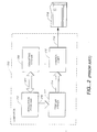
- FIG. 2 is a schematic illustration of a typical computer system utilizing an application program, an operating system and a printer driver.
- the computer system is schematically represented by dotted box 200
- the application program is represented by box 202
- the operating system by box 206.
- the interaction between the application program 202 and the operating system 206 is illustrated schematically by arrow 204.
- This dual program system is used on many types of computers systems ranging from mainframes to personal computers.
- FIG. 2 represents a typical prior art personal computer system.
- the application program 202 interacts (as shown schematically by arrow 208) with printer driver software 210.
- the printer driver software 210 generally performs halftoning operations and may perform other operations to produce a reformatted information stream containing embedded commands and converted graphical information as shown schematically as arrow 214.
- the converted information stream is, in turn, applied to a printer port 212 which contains circuitry that converts the incoming information stream into electrical signals.
- the signals are, in turn, sent over a cable 216 to the printer 218.
- Printer 218 usually contains a "imaging engine”, which is a hardware device or a ROM-programmed computer which takes the incoming information stream and converts it into the electrical signals necessary to drive the actual printing elements. The result is a "hard copy” output on the selected medium.
- the present invention and the apparatus which performs the error diffusion process may also be incorporated into specialized hardware located in the printer port 212 of the printer 218 itself.
- a printer printing at a resolution of 720 dpi and having dots with a radius of /dpi ⁇ r ⁇ 2/ dpi tends to print redundant information.
- the dots representing pixels 1001d and 1002d overlap in a region of pixel 1004d.
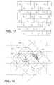
- only alternate pixels will be processed and printed on each line. For example, as shown in FIG. 17 on the odd numbered lines on the odd column pixels and on the even numbered lines only the even column pixels are processed and printed.
- the error diffusion process itself is well-known and is, for example, described in detail in " Digital Halftoning " " by Robert Ulichney, printed by the MIT Press, Cambridge, Massachusetts and London, England ,1990, at pps. 239-319.
- the pixels which comprise the original image are processed on a line-by-line fashion and, in each line, the pixels are processed in single direction (from left-to-right or right-to-left).
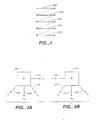
- a common line processing pattern is shown in FIG. 3 where each of the pixel lines 300, 302, 304, 306 and 308 is processed from left-to-right, then the next line is processed from left-to-right, and the following line is processed from left to right, etc. until the entire image is processed in the top to bottom direction.
- FIG. 4A illustrates diffusion of the error generated during the processing of each pixel to neighboring pixels in the case where processing proceeds along the line in the left-to-right direction.
- each pixel is processed by comparing its value to a predetermined threshold value where the pixel "value" is the original grayscale value plus error adjustments resulting from the previous processing of other pixels. If the value of the pixel exceeds the threshold value, then a "1" or dot is output. Alternatively, if the value of the pixel is less than the threshold value, then a "0" or no dot is output. An error value is then determined by subtracting the value of the dot which is actually output from the input value. This error is then "diffused” or spread among neighboring, but unprocessed, pixels.
- FIG. 4A This "diffusion" process is illustrated in FIG. 4A where the pixel being processed is depicted as box 400.
- the error resulting from the processing is spread to the neighbonng pixel to the immediate right of the processed pixel 400 (as indicated by arrow 402) and to three neighboring pixels on the next line of binary pattern pixels as indicated by arrows 404, 406 and 408.
- the error value is multiplied by a proportionality constant.
- FIG. 4B The diffusion process in the case where the pixel processing takes place in the right-to-left direction is illustrated in FIG. 4B where the pixel being processed is depicted as box 410.
- the error resulting from the processing is spread to the neighboring pixel to the immediate left of the processed pixel 410 (as indicated by arrow 412) and to three neighboring pixels on the next line of binary pattern pixels as indicated by arrows 414, 416 and 418.
- the error value is also multiplied by a proportionality constant.
- Another known method, descnbed in Japanese Laid-Open Patent HEI 3-151762/91, of minimizing the appearance of worms also varies the processing sequence from the conventional raster pattern.
- the processing direction for each image line is selected based on the output of a random number generator or noise pattern generator which is quantized to yield a stream of "1's" and "0's". Pixel processing for each line is therefore performed left-to-nght (in response to a "1") or night-to-felt (in response to a "0") in a random pattern.
- pixels in image lines are processed left-to-right and right-to-left in predetermined periodic patterns, e.g., two left-to-right scans, followed by two right-to-left scans, and so on. While these prior processing order techniques reduce the size of the worms, the worms are still visible in the halftoned image.
- each selected pixel is processed by comparing its value to a predetermined threshold where the pixel "value" is the original grayscale value plus error adjustments resulting from the previous processing of other pixels. If the value of the pixel exceeds the threshold value, then a "1" or dot is output. Alternatively, if the value of the pixel is less than the threshold value, then a "0" or no dot is output. An error value is then determined by subtracting the value of the dot which is actually output from the input value. This error is then "diffused” or spread among neighboring, but unprocessed, pixels.
- FIGS. 4A and 4B are illustrative examples of error diffusion in the right-to-lett and left-to right directions
- FIG. 11 This "diffusion" process is illustrated in FIG. 11 where the pixel being processed is depicted as pixel 1501. As noted above, only every other pixel is processed. Accordingly. there is no error diffusion processing of the unselected pixels. In the illustrated arrangement, the error resulting from the processing is spread to a neighboring pixel 1502 to the right of the processed pixel 1501 (skipping the pixel immediately adjacent thereto), to the two neighboring pixels 1503, 1506 on the next line of binary pattern pixels skipping the pixel immediately below pixel 1501), and to the three neighboring pixels on the following line 1504, 1505, 1507. Before being added to the neighboring pixels, the error value is multiplied by a proportionality constant.
- the diffusion process in the case where the pixel processing takes place in the right-to-left direction is illustrated in FIG. 11 where the pixel 1601 is processed.
- the error resulting from the processing is spread to the neighboring pixel 1602 to the left of the processed pixel 1601, to the two neighboring pixels 1603, 1606 on the next line, and to the three neighboring pixels on the following line 1604, 1605, 1607. of binary pattern pixels.
- the error value is also multiplied by a proportionality constant.
- the neihgboring pixel 1602 to the right of pixel 1601 is processed by adding the proportionalized error value to the pixel value and processing it in the same manner as pixel 1601.
- FIG. 5 is an illustrative schematic block diagram that shows an error diffusion circuit modified in accordance with the principles of the invention. While the block diagram in FIG. 5 is preferred, persons of ordinary skill in the art who have read this description will recognize that various modification and changes may be made therein.
- the error diffusion circuit receives a stream 500 of grayscale image pixels represented by digital words from an imaging device (not shown) in a conventional manner.
- the stream of image pixels are entered serially into a conventional Input buffer 502.
- Buffer 502 is, in general, of sufficient size to store incoming image pixel words for an entire line of pixels.
- Buffer 502 is, in turn, controlled by buffer control circuit 510 (as indicated schematically by arrow 512) to output every other or alternately stored values, in line order, to both the summing circuit 506 and to the arithmetic or logic circuit 514.
- buffer control circuit 510 as indicated schematically by arrow 512
- the odd column pixels are outputted and in the even numbered lines, the even pixels are outputted in response to buffer control 510.
- the summing circuit 506 is used to subtract the "error" values produced by the processing of previous pixels as will be described further below
- the arithmetic or logic circuit 514 is used to control the processing direction, in accordance with any of the techniques descnbed above.
- buffer 502 can serially the stored pixel data either in a "left-to-right” order (last-in, first-out) or can output the stored pixel data in a "right-to-left” order (first-in, first-out).
- the stored input data produced at the output 504 of input buffer is applied to the threshold circuit 528 by way of summing circuit 506 and line 508.
- the output of threshold circuit 528 is a quantized binary image (comprised of "0's” and “1”s") which is produced by comparing the pixel values (each pixel “value” compnses the original input image value and "error” adjustments introduced by summing circuit 506) to a predetermined, fixed threshold value and outputting a "1” if the pixel value is greater than the threshold and outputting a "0” if the pixel value is less than or equal to the threshold value.
- the threshold circuit 528 may use a fixed threshold value such as 0.5 (for a grayscale value range between 0 and 1).
- the quantized binary signal generated by the threshold circuit 528 is applied, via output line 532, to a second summing circuit 530 which subtracts the unquantized input signal on line 508 from the quantized output from threshold circuit 528 on line 532 to generate a quantization error value.
- the quantization error value is applied to filter circuit 522.
- the filter circuit 522 multiplies the error value by proportionality coefficients to generate the diffused error values, one of which will be added to the next pixel to be processed by summing circuit 506 and the rest of which are stored in error buffer 5 is to be added to pixels during processing of the next and following lines of pixels.
- Error buffer 518 is also controlled by buffer control circuit 510 (as indicated schematically by arrow 516) to output selected stored values to both summing circuit 506 and to the arithmetic or logic circuit 514 (via output line 524). Under control of the buffer control circuit 510, error buffer 518 can serially output the stored pixel data either in a "left-io-right” order (last-in, first-out) or can output the stored pixel data in a "right-to-left' order (first-in, first-out) in order to match the error data with the input data being shifted out of input buffer 502.
- buffer control circuit 510 controls both input buffer 502 and error buffer 518 to sequentialy provide in input pixel value from buffer 502 to summing circuit 506 and an error value from error buffer 518 to summing circuit 506. Summing circuit then provides sequentialy error-diffused values to threshold circuit 528 which generates the quantized output. The output of the threshold circuit 528 is also provided to the output buffer 534 which is also controlled by buffer control circuit 510. Output buffer 534 can output a serial stream of binary pixels for provision to the printing device on line 536.
- FIGS. 13-A and 13-B illustrate operation of the second embodiment of the invention.
- the pixels to be processed are selected in a manner as described hereinabove.
- I utilize a different form of function g(x) a representative version of which appears in FIG. 13- A.
- Suitable transform functions to implement this aspect of the invention are most conveniently based on the printer function f(x) , which, it will be recalled, relates the gray scale of incoming source data to the gray scale at which it will actually be rendered on the printer.
- FIG. 15 A representative hardware implementation of this aspect of the invention appears in FIG. 15.
- multibit image data (arriving, for example, from a digital scanner that samples the density of a source document in discrete steps and over a fixed range of gray-scale values) arrives as a stream of N-bit values and accumulates in a data buffer 20. Every other pixel data in data buffer 20 is read out therefrom by pixel selector circuit 21. The selected data is then transferred to a filter 22, which modifies each N-bit density value according to the transform function described above.
- a user-actuated adjustment feature 24 which may be in the form of a slide switch or a digitally programmable input device, imposes a selected value of the weighting factor w on the transform filter function, thereby modulating its operation.
- the modified N-bit image data is transferred to a halftone engine 26, which coverts the incoming data into a raster pattern of 1-bit elements according to a suitable halftone processing algorithm.
- the invention is suitably used in conjunction with a variety of such algorithms, including globally fixed-level thresholding, constrained-average thresholding, dynamic thresholding, orthographic tone-scale creation, so-called electronic screening algorithms, various dithering algorithms (including ordered dither techniques such as dispersed-dot dithering) and error-diffusion techniques.
- the raster output of halftone engine 26 is delivered to a conventional electronic printer 28, which applies ink or toner to a recording medium in accordance with the raster pattern.
- a halftone filter 30 modifies halftone engine 26 such that the final halftone output is biased in accordance with the function g(x) .
- each array value is treated as a discrete intensity level, and a filter function applied thereto to obtain modified values. Because the array values represent (or translate into) thresholds rather than intensities, the inverse function g ⁇ 1(x), rather than g(x) , is applied to the arrav values.
- Halftoning engine 26 applies the filtered dither array to selected pixel data as described above. As noted above, the selected pixel data comprises every other pixel data representing the source image. This may be implemented by pixel selector circuit 21 shown in FIG. 16.
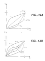
- FIGS. 14-A and 14-B Application of this technique is shown in FIGS. 14-A and 14-B. Since printed output densities of the printer follow the typical f(x) pattern, the dither array threshold values, to which source data are compared, are generally arranged to reflect an opposite inherent bias f ⁇ 1(x) ; in this way, when the comparison between input source data and dither-array threshold values is made, the overall output density will be approximately the same as the input density.
- curves b and d represent intermediate cases.
- the values in the modified dither array may be directly compared with the source data values as halftone thresholds that determine whether corresponding raster points are to be colored or uncolored; or the dither array may instead be tiled onto those values on an iterative basis, augmenting the density value of each source pixel by the value of the applied dither array cell prior to comparison with a fixed threshold.
- the dither array and intermediate arrays used to derive the dither array contain only enough elements to correspond to every other pixel processed.
- the dither array and any intermediate arrays contain 1 x k elements in which each of the 1 x k elements is in corresponding relation to only the n/2 x m elements.
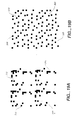
- FIG. 19A shows a typical starting pattern (called a "Prototype Binary Pattern") which can be used in accordance with the prior art void-and-cluster dither array generation method.
- a pattern such as that shown in FIG.
- 19A might, for example, be generated by taking the output of a white noise generator and quantizing it to a pattern of binary "1's" and "0's” by comparing the white-noise values to a fixed threshold and inserting a "1" where the noise value exceeds the threshold and inserting a "0" where the noise value is less then the threshold.
- the pattern shown in FIG. 19A actually consists of four identical tile patterns, 300, 302, 304 and 306.
- the Prototype Binary Pattern used as the starting point of the prior art dither array generation method would actually consist of one of these patterns, however, four are shown to iilustrate how the patterns can be used to tile a two-dimensional image.
- the Prototype Binary Pattern shown in FIG. 19A is used with the prior art void-and-cluster method, the pattern is directly homogenized by removing pixels from the tightest clusters and placing them in the largest voids.
- a pattern, such as pattern 300 shown in Figure 19A is not homogeneous to start with due to the coarse quantizing.
- a more homogeneous patten is generated before further homogenization is performed by removing pixels from the tightest clusters and placing them in the largest voids.
- the generation of this more homogeneous starting pattern begins with an array which is filled with identical grayscale values.
- Each of the values represents a consuant gray tone with value less than one half of the total scale. For example, in an eight-bit per pixel system (with a maximum value of 255 for each pixel), each element of the array would be initially filed with the same number, which number has a value of less than 127.
- the error diffusion process used to process the Prototype Gray Pattern is applied to every other pixel as described hereinabove, as shown, for example, in FIG. 11. Accordingly a discussion of the error diffusion is omitted.
- the binary pattern thereinafter called the "Starting Binary Pattern" resulting from the application of the error diffusion process to the Prototype Gray Pattern can be used directly as the starting pattern for the prior art void-and-cluster processing homogenization step.
- the Starting Binary Pattern resulting from the application of the error diffusion process to the Prototype Gray Pattern
- another correction is made to the Starting Binary Pattern to account for "oversized" dots produced by printing devices such as inkjet or laser printers.
- the conventional void-and-cluster dither array generation method assumes that the output pixels are square so that neighboring pixels abut each other with no overlap.
- This pixel shape is shown in FIG. 6 where the pixel assumed by the prior art void and cluster method is shown as square pixel 1003.
- many printing devices actually generate a circular dot such as dot 1002d, as shown in FIG 9-B and discussed above. This diameter of this dot is generally larger than the square pixel area so that dots corresponding to adjacent pixels will overlap to eliminate all white spots in an "all-black" area.
- dots 1001d and 1002d that it is unnecessary to process or print the pixel 1004d disposed therebetween.
- dot 1001d is larger than the pixel it represents so that the overlap area is not taken into account in the void-and-cluster method.
- the void-and-cluster method must be arranged such that the Prototype Binary Pattern, the Prototype Gray Pattern and the Starting Binary Pattern contain the same number of elements as the number of pixels that are printed. For example, if there are n x m pixels, only every other pixel or n/2 x m pixels are printed. Therefore these patterns contain only those elements which correspond to the n/2 x m pixels. This is accomplished, in effect, by transposing the array for these patterns by, for example 45°, and shown in FIG. 18. Additionally, the shape and location of these three distinct areas is shown therein.
- FIG. 18 shows three "on" pixels, 600, 602 and 604, and the accompanying printer dots 606, 608 and 610 which would be used to represent the three pixel areas 600, 602 and 604.
- the overlap caused by the oversized printer dots results in three distinct area types can be used either singularly, or in combination. to correctly adjust adjacent areas for dot overlaps. These areas are illustrated as the shaded areas shown in FIG. 18.
- first area type, 612 is designated as an " ⁇ " area.
- the next area type is area 614 designated as a " ⁇ " area
- the third area type (caused by an overlap of two dots) is area 616 called a " ⁇ " area.
- the sizes of the ⁇ , ⁇ and ⁇ areas are fixed for each particular type of printer and depend on the printer dot radius and the printer resolution.
- the dot radius for any particular printer can be determined by examining the dots produced by the printer under a microscope. Once the dot radius has been ascertained, a normalized radius (r o ) can be computed using the formula: where "dpi" is the "dots per inch" resolution of the printer.
- the radius of the pixels, of which the present invention is directed to is generally in the range of / dpi ⁇ r ⁇ 2/dpi .
- FIG.20A and 20B illustrate how corrections are made to the either the Prototype Binary Pattern (the white noise pattern used in the prior art void-and-cluster method) or the Starting Binary Pattern (the Prototype Gray Pattern after error diffusion has been applied) to account for oversized dots. Additionally those figures illustrate that these patterns have been transposed by 45°.
- FIG. 20A shows a section of the pattern, for example which might be a section of the pattern shown in either of FIGS. 19A or 19B which is generated assuming square pixels.
- the pattern comprises a rectangular array of "1's” and "0's” and the particular section of the array shown in FIG. 20A consists of mostly “0's" with three "1's” located in array elements 700, 702 and 704.
- FIG. 20B shows the same array portion which has been corrected for effects of the oversized dots.
- array element 708 in FIG. 20B now has been adjusted by adding the value of " ⁇ " to the original value ("0").
- the adjustment arises from the overlap area produced by the dot located in element 710. Accordingly, this value is changed from the original "0" value in the corresponding element 706 in FIG. 20A.
- the values in the array elements surrounding the three “1's" are adjusted in accordance with the overlap areas produced by the oversized dots as illustrated in FIG. 20B.
- These adjustments impart “grayscale” values to the surrounding elements and tend to further refine the dot patterns. Due to the added grayscale values this pattern is hereinafter called a "Starting Gray Pattern".
- both the Starting Binary Pattern (as shown in FIG. 19B) and the Starting Gray Pattern (as shown in FIG. 20B) are then subjected to void-and-cluster processing to create an Initial Binary Pattern and an initial Gray Pattern, respectively, by moving pixels from clusters to voids. It has been found that the additional adjustments as illustrated in FIGS. 19B and 20B further enhance the quality of the dither array generated by the inventive void-and-clusier method.
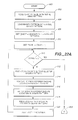
- FIG. 21 is an illustrative flowchart of the inventive void and cluster method incorporating the improvements discussed above. Although the improvements are applied in the method illustrated in FiG. 21, it should be understood that any of the improvement steps can be applied independent of each other to generate an improved dither array.
- the inventive method starts in step 800 and proceeds to step 801 where the elements of the Gray Pattern are arranged to correspond to every other pixel (the selected pixels). As shown in FIG. 18 the Gray Pattern is transposed by approximately 45°, so that each element of the Gray Pattern array corresponds to each of the selected pixels.
- step 802 the Prototype Gray Pattern is generated, illustratively using a constant value in each array element.
- an error diffusion process is applied to the Prototype Gray Pattern to generate the Starting Binary Pattern. It is noted that the Starting Binary Pattern array contains the same number of elements as the number of selected pixels.
- step 806 the Starting Binary Pattern is adjusted for oversized dot patterns as discussed above and shown in FIG. 20A and 20B to generate the Starting Gray Pattern.
- step 808 the Initial Binary Pattern and the Initial Gray Pattern are created from the Starting Binary Pattern and the Starting Gray Pattern, respectively, by moving pixels from clusters to voids in the manner discussed above in accordance with the prior art void-and-cluster method.
- step 810 threshold values are assigned to the dither array using the Initial Binary Pattern and the Initial Gray Pattern using the method discussed in detail in connection with Figures 22A-22C.
- the routine then finishes in step 812.
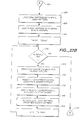
- Figures 22A, 22B and 22C when placed together, disclose an illustrative method for assigning threshold values to the dither array utilizing the Initial Gray Pattern and the Initial Binary Pattern.
- the disclosed method that is similar to that used in the conventional void-and cluster-method, however, the method has been modified to use the Initial Gray Pattern to locale the voids and the clusters instead of the Initial Binary Pattern used in the prior an method. Since the Initial Gray Pattern has been adjusted for the effects of oversized dots, it produces a more accurate location for the tightest clusters and largest voids.
- the illustrated method has three phases. During Phase I(shown in Figure 22A) the dither array elements from element numbers ("Ones"-1) to 0 are entered. During Phase II (shown in Figure 22B), dither array elements from "Ones" to are added and, in Phase III (shown in Figure 22C) elements to lk are entered.
- the illustrative routine starts in step 900 and proceeds to step 902 where a Gray Pattern Array is loaded with the initial Gray Pattern.
- the routine uses two arrays called a "Gray Pattern" array and a Binary Pattern" array. These arrays have the same number of elements as the dither array (arbitrarily, they are taken to have l rows and k columns).
- the Gray Pattern array is loaded with the values taken from the Initial Gray Pattern array generated as described above.
- step 904 the Binary Pattern array is loaded with the Initial Binary Pattern array values generated as discussed above.
- a variable "Ones” is set equal to the number of ones in the Binary Pattern
- a variable "Rank” is set equal to the value of the variable "Ones" minus "l”.
- step 910 the variable "Rank” is checked to see if it is less than zero. This check determines whether Phase I of the threshold, assignment routine has been completed. If the value of "Rank" is not less than zero, then the routine proceeds to step 912 in which the location of the tightest cluster in the Gray Pattern array is determined. As previously mentioned, this determination is made by using a two-dimensional Gaussian filter (described above). This filter takes into account the adjusted gray scale values in the Gray Pattern to locate the tightest cluster.
- step 914 a binary "1" is removed from the Binary Pattern at the location determined in step 912 to form a New Binary Pattern. Subsequently, the value of the "Rank” variable is entered into the corresponding location in the dither array in step 916 to form the new threshold value.
- step 914 the removal of the "1" from the Binary Pattern forces a readjustment of the grayscale values because the ⁇ , ⁇ and ⁇ values must be reajusted to take into account the fact that the "1" has been removed and a "0" has been inserted in its place. Consequently, in step 918, the Gray Pattern is recalculated from the New Binary Pattern produced by removing the "1" in step 914.
- step 920 the value of the "Rank" variable is decremented and the routine proceeds back to step 910 where a further check is made to determine whether the end of Phase I has been reached. If so, the routine proceeds, via off-page connectors 922 and 924, to Phase II, as shown in Figure 22B. Alternatively, if, in step 910, the value of the "Rank" variable is not less than zero, then steps 912-920 are repeated and the routine continues in this matter until Phase I has been completed.
- Figure 22B shows the steps performed in Phase II of the inventive threshold assignment method.
- the routines proceeds to step 926 in which the Gray Pattern array is initialized by loading it with the Initial Gray Pattern values determined previously.
- the Binary Pattern array is initialized by loading it with the Initial Binary Pattern values determined previously.
- the value of the "Rank" variable is set equal to the value of the "Ones" variable.
- step 932 a check is made to determine whether the value of the "Rank” variable is less than the number of rows times the number of columns divided by two Since the value of the "Rank” variable will increase with each pass through the routine loop, the value of the "Rank” variable will eventually exceed the value and the routine will proceed to Phase III of the threshold assignment method as indicated in step 932
- step 932 determines that remaining "voids" need to be processed. If, in step 932, it is determined that remaining "voids" need to be processed, the routine proceeds to step 934 where the location of the largest void in the Gray Pattern array is determined, again by using the two-dimensional Gaussian filter as described above.
- step 936 a binary "1" is inserted into the corresponding location in the Binary Pattern thereby replacing the original "0” to form a New Binary Pattern and, in step 938, the value of the "Rank” variable is entered into the corresponding location of the dither array.
- the Gray Pattern array is then recalculated from the New Binary Pattern to adjust for the "0" to "1" replacement in step 936 and the value of the "Rank” variable is incremented by one in step 942.
- the routine then proceeds back to step 932 in which the value of the "Rank” variable is again checked to determine whether Phase II has been completed. If Phase II has not been completed, steps 934-942 are repeated. At the completion of Phase II as indicated by the value of the "Rank” variable exceeding the routine proceeds, via off-page connectors 944 and 946, to Phase III of the threshold assignment routine as shown in detail in Figure 22C.
- the routine proceeds to from off-page connector 946 to step 948 where the definition of "minority pixels” is changed from “1” to "0" (as previously mentioned, during Phase II the arrays are being filled with binary “1s” and thus binary "1s", which were originally the "minority” pixel, have now become the "majority” pixels).
- the routine then proceeds to step 950 where the value of the "Rank” variable is checked to see if it is less than the number of rows times the number columns (lk).
- the value of the "Rank” variable increases and, thus, it will eventually equal lk, at which point the routine will finish.
- each of the l x k elements of the dither array now correspond to each of the n/2 x m selected pixels.
- step 950 a determination is made that the value of the "Rank” variable is less than lk
- the routine proceeds to step 952 where the location of the tightest cluster in the Gray Pattern array is determined, again using the previously-described Gaussian filter.
- step 954 a "1" is inserted into the Binary Pattern at the location determined in step 952 to form a New Binary Pattern, and, in step 956, the value of the "Rink” variable is entered into the corresponding location in the dither array.
- the Gray Pattern array is recalculated from the New Binary Pattern in Step 958 and the value of the "Rank" variable is incremented in step 960.
- the routine then proceeds back to step 950 to make a determination whether Phase III has been completed. If so, the routine ends in step 962, if not, steps 952 through 960 are repeated until all elements of the dither array have been assigned a threshold value.
Landscapes
- Engineering & Computer Science (AREA)
- Multimedia (AREA)
- Signal Processing (AREA)
- Image Processing (AREA)
- Facsimile Image Signal Circuits (AREA)
- Particle Formation And Scattering Control In Inkjet Printers (AREA)
- Dot-Matrix Printers And Others (AREA)
- Compression Of Band Width Or Redundancy In Fax (AREA)
Applications Claiming Priority (2)
| Application Number | Priority Date | Filing Date | Title |
|---|---|---|---|
| US320534 | 1994-10-11 | ||
| US08/320,534 US5684932A (en) | 1994-07-01 | 1994-10-11 | Method and apparatus for dither array generation to reduce artifacts in halftoned image data utilizing ink reduction processing |
Publications (3)
| Publication Number | Publication Date |
|---|---|
| EP0707411A2 true EP0707411A2 (de) | 1996-04-17 |
| EP0707411A3 EP0707411A3 (de) | 1996-12-04 |
| EP0707411B1 EP0707411B1 (de) | 2000-03-22 |
Family
ID=23246859
Family Applications (1)
| Application Number | Title | Priority Date | Filing Date |
|---|---|---|---|
| EP95307164A Expired - Lifetime EP0707411B1 (de) | 1994-10-11 | 1995-10-11 | Verbessertes Verfahren und Gerät zur Erzeugung von Zittermatrizen zur Herabsetzung von Artefakten in Halbtonbilddaten unter Verwendung von Tintenverminderungsverarbeitung |
Country Status (4)
| Country | Link |
|---|---|
| US (1) | US5684932A (de) |
| EP (1) | EP0707411B1 (de) |
| JP (1) | JPH08195883A (de) |
| DE (1) | DE69515782T2 (de) |
Families Citing this family (20)
| Publication number | Priority date | Publication date | Assignee | Title |
|---|---|---|---|---|
| US5854882A (en) * | 1994-04-08 | 1998-12-29 | The University Of Rochester | Halftone correction systems |
| US5841951A (en) * | 1996-02-09 | 1998-11-24 | Seiko Epson Corporation | Ink duty-cycle control |
| US5953459A (en) * | 1996-02-23 | 1999-09-14 | Brother Kogyo Kabushiki Kaisha | Dither matrix producing method |
| US5799136A (en) * | 1996-05-28 | 1998-08-25 | Seiko Epson Corporation | On-line ink-duty reduction |
| US5848224A (en) * | 1996-09-26 | 1998-12-08 | Hewlett-Packard Company | Optimally pipelined error diffusion architecture for converting scanned image into four-color printed image |
| US5796929A (en) * | 1996-10-24 | 1998-08-18 | Seiko Epson Corporation | Banding and ink-bleeding reduction in cluster dither by screen displacement |
| JP3905650B2 (ja) * | 1998-08-31 | 2007-04-18 | 武藤工業株式会社 | 疑似階調表現方法 |
| US6356362B1 (en) | 1998-11-02 | 2002-03-12 | Canon Kabushiki Kaisha | Halftoning by enhanced error diffusion |
| US6407825B1 (en) * | 1998-12-17 | 2002-06-18 | Eastman Kodak Company | Colorant reduction method for digital images |
| KR100575975B1 (ko) * | 1999-10-06 | 2006-05-02 | 삼성전자주식회사 | 레이저 빔 프린터에서 그레이 성분을 가진 이미지의 다치화 처리회로 및 방법 |
| US6731822B1 (en) * | 1999-10-28 | 2004-05-04 | Hewlett-Packard Development Company, L.P. | Method and apparatus for filtering images having insufficient tonal precision |
| WO2002071738A1 (fr) * | 2001-03-02 | 2002-09-12 | Dai Nippon Printing Co., Ltd. | Procede de creation d'un masque de tremblement et dispositif de creation |
| US7319542B2 (en) * | 2002-10-29 | 2008-01-15 | Hewlett-Packard Development Company, L.P. | Document rehabilitation |
| US7239429B2 (en) * | 2003-05-29 | 2007-07-03 | Seiko Epson Corporation | Method and apparatus for generating dispersed cluster screen |
| US7265872B2 (en) * | 2003-10-15 | 2007-09-04 | International Business Machines Corporation | Error diffusion with averaged directional biases |
| KR100611981B1 (ko) * | 2004-05-01 | 2006-08-11 | 삼성전자주식회사 | 이미지의 하프토닝 방법 및 장치 |
| CN100393098C (zh) * | 2006-08-22 | 2008-06-04 | 北京大学 | 误差扩散图像挂网技术中的图像扫描处理方法及系统 |
| US20080259079A1 (en) * | 2007-04-18 | 2008-10-23 | Boxman Benjamin D | Method and system for volume rendering |
| TW201011699A (en) * | 2008-09-12 | 2010-03-16 | Univ Nat Taiwan Science Tech | Image compression method using block truncation coding |
| GB2473475B (en) * | 2009-09-11 | 2014-12-17 | Andrew William Peter Cave | Computer program for generating 1-bit image data from multiple-bit image data |
Family Cites Families (15)
| Publication number | Priority date | Publication date | Assignee | Title |
|---|---|---|---|---|
| US4752822A (en) * | 1983-03-08 | 1988-06-21 | Canon Kabushiki Kaisha | Color halftone image processing apparatus producing various screen angles and having an adaptive color image data conversion look-up table and a small-capacity masking memory |
| US4680645A (en) * | 1986-08-25 | 1987-07-14 | Hewlett-Packard Company | Method for rendering gray scale images with variable dot sizes |
| US4955065A (en) * | 1987-03-17 | 1990-09-04 | Digital Equipment Corporation | System for producing dithered images from continuous-tone image data |
| US4855752A (en) * | 1987-06-01 | 1989-08-08 | Hewlett-Packard Company | Method of improving dot-on-dot graphics area-fill using an ink-jet device |
| US4943813A (en) * | 1987-06-01 | 1990-07-24 | Hewlett-Packard Company | Method of generating overhead transparency projecting using an ink-jet device |
| US5201013A (en) * | 1989-04-24 | 1993-04-06 | Ezel, Inc. | Dither processing method |
| US4967203A (en) * | 1989-09-29 | 1990-10-30 | Hewlett-Packard Company | Interlace printing process |
| US4999646A (en) * | 1989-11-29 | 1991-03-12 | Hewlett-Packard Company | Method for enhancing the uniformity and consistency of dot formation produced by color ink jet printing |
| US5031050A (en) * | 1990-02-26 | 1991-07-09 | Hewlett-Packard Company | Method and system for reproducing monochromatic and color images using ordered dither and error diffusion |
| US5278671A (en) * | 1990-10-05 | 1994-01-11 | Nippon Steel Corporation | Image processing apparatus with correction of diffusion errors of overlapping dots |
| US5270728A (en) * | 1991-04-17 | 1993-12-14 | Hewlett-Packard Company | Raster imaging device speed-resolution product multiplying method and resulting pixel image data structure |
| US5535020A (en) * | 1992-10-15 | 1996-07-09 | Digital Equipment Corporation | Void and cluster apparatus and method for generating dither templates |
| US5313287A (en) * | 1993-04-30 | 1994-05-17 | Hewlett-Packard Company | Imposed weight matrix error diffusion halftoning of image data |
| US5317418A (en) * | 1993-05-11 | 1994-05-31 | Hewlett-Packard Company | Halftone images using special filters |
| US5557709A (en) * | 1994-07-01 | 1996-09-17 | Seiko Epson Corporation | Method and apparatus for dither array generation to reduce artifacts in halftoned images |
-
1994
- 1994-10-11 US US08/320,534 patent/US5684932A/en not_active Expired - Fee Related
-
1995
- 1995-10-03 JP JP7256636A patent/JPH08195883A/ja active Pending
- 1995-10-11 EP EP95307164A patent/EP0707411B1/de not_active Expired - Lifetime
- 1995-10-11 DE DE69515782T patent/DE69515782T2/de not_active Expired - Lifetime
Non-Patent Citations (4)
| Title |
|---|
| JOURNAL OF ELECTRONIC IMAGING, vol. 2, no. 3, July 1993, BELLINGHAM, WA (US), pages 193-204, XP000394878 T. N. PAPPAS ET AL.: "Measurement of printer parameters for model-based halftoning" * |
| JOURNAL OF ELECTRONIC IMAGING, vol. 2, no. 3, July 1993, BELLINGHAM, WA (US), pages 205-212, XP000394879 C. J. ROSENBERG: "Measurement-based evaluation of a printer dot model for halftone algorithm tone correction" * |
| Proceedings; SPIE - The International Society for Optical Engineering; Human Vision, Visual Processing, and Digital Display IV; 1-4 February 1993, San Jose, XP000472838 * |
| Society for Information Display, International Symposium, 14-16 June 1994, San Jose, California (US), Digest of Technical Papers,Vol. 25, SID, 1994 XP002015281 * |
Also Published As
| Publication number | Publication date |
|---|---|
| DE69515782D1 (de) | 2000-04-27 |
| DE69515782T2 (de) | 2000-08-10 |
| EP0707411B1 (de) | 2000-03-22 |
| EP0707411A3 (de) | 1996-12-04 |
| US5684932A (en) | 1997-11-04 |
| JPH08195883A (ja) | 1996-07-30 |
Similar Documents
| Publication | Publication Date | Title |
|---|---|---|
| EP0707412B1 (de) | Verfahren und Gerät zur Herabsetzung von Artefakten in mittels Halbtonfehlerdiffusion erzeugten Bildern unter Verwendung von Tintenverminderungsverarbeitung | |
| EP0707411B1 (de) | Verbessertes Verfahren und Gerät zur Erzeugung von Zittermatrizen zur Herabsetzung von Artefakten in Halbtonbilddaten unter Verwendung von Tintenverminderungsverarbeitung | |
| US5557709A (en) | Method and apparatus for dither array generation to reduce artifacts in halftoned images | |
| Ulichney | Review of halftoning techniques | |
| US5757976A (en) | Adaptive filtering and thresholding arrangement for reducing graininess of images | |
| US5321525A (en) | Clustered halftoning with dot-to-dot error diffusion | |
| US5268774A (en) | Halftoning with enhanced dynamic range and edge enhanced error diffusion | |
| Pappas et al. | Printer models and error diffusion | |
| US6563957B1 (en) | Tone dependent error diffusion | |
| US5543935A (en) | Halftoning method using space filling curves | |
| US4651287A (en) | Digital image processing algorithm for output devices with discrete halftone gray scale capability | |
| US5325211A (en) | Error diffusion with output and input based feedback | |
| Pappas et al. | Model-based halftoning | |
| US5625755A (en) | Method and apparatus for tonal correction in binary printing devices by predistortion of image data utilizing ink reduction processing | |
| US5692109A (en) | Method and apparatus for minimizing artifacts in images produced by error diffusion halftoning | |
| EP1366618B1 (de) | Verfahren und system zur fehlerdiffusion bei teilhalbtonpunkten | |
| US5568572A (en) | Method and apparatus for tonal correction in binary printing devices by predistortion of image data | |
| US6844941B1 (en) | Color halftoning using a single successive-filling halftone screen | |
| US20040090654A1 (en) | FM screening with sub-dot phase modulation | |
| US6141121A (en) | Method and apparatus for color halftoning | |
| KR20000026847A (ko) | 화상 데이터 처리장치 | |
| US6597813B1 (en) | Masks with modulated clustering and aperiodicity and rescaling of masks | |
| US5898822A (en) | Using the phase information in the halftone dot structure to minimize artifacts when switching between halftone dots on a scan line | |
| Yao et al. | Dot gain compensation in the blue noise mask | |
| EP1401189A1 (de) | FM Rasterung mit Phasenmodulation von Unterpunkten |
Legal Events
| Date | Code | Title | Description |
|---|---|---|---|
| PUAI | Public reference made under article 153(3) epc to a published international application that has entered the european phase |
Free format text: ORIGINAL CODE: 0009012 |
|
| AK | Designated contracting states |
Kind code of ref document: A2 Designated state(s): DE FR GB |
|
| PUAL | Search report despatched |
Free format text: ORIGINAL CODE: 0009013 |
|
| AK | Designated contracting states |
Kind code of ref document: A3 Designated state(s): DE FR GB |
|
| 17P | Request for examination filed |
Effective date: 19970515 |
|
| 17Q | First examination report despatched |
Effective date: 19981214 |
|
| GRAG | Despatch of communication of intention to grant |
Free format text: ORIGINAL CODE: EPIDOS AGRA |
|
| GRAG | Despatch of communication of intention to grant |
Free format text: ORIGINAL CODE: EPIDOS AGRA |
|
| GRAH | Despatch of communication of intention to grant a patent |
Free format text: ORIGINAL CODE: EPIDOS IGRA |
|
| GRAH | Despatch of communication of intention to grant a patent |
Free format text: ORIGINAL CODE: EPIDOS IGRA |
|
| GRAA | (expected) grant |
Free format text: ORIGINAL CODE: 0009210 |
|
| AK | Designated contracting states |
Kind code of ref document: B1 Designated state(s): DE FR GB |
|
| REF | Corresponds to: |
Ref document number: 69515782 Country of ref document: DE Date of ref document: 20000427 |
|
| ET | Fr: translation filed | ||
| PLBE | No opposition filed within time limit |
Free format text: ORIGINAL CODE: 0009261 |
|
| STAA | Information on the status of an ep patent application or granted ep patent |
Free format text: STATUS: NO OPPOSITION FILED WITHIN TIME LIMIT |
|
| 26N | No opposition filed | ||
| REG | Reference to a national code |
Ref country code: GB Ref legal event code: IF02 |
|
| PGFP | Annual fee paid to national office [announced via postgrant information from national office to epo] |
Ref country code: FR Payment date: 20101020 Year of fee payment: 16 |
|
| PGFP | Annual fee paid to national office [announced via postgrant information from national office to epo] |
Ref country code: DE Payment date: 20101006 Year of fee payment: 16 |
|
| PGFP | Annual fee paid to national office [announced via postgrant information from national office to epo] |
Ref country code: GB Payment date: 20101006 Year of fee payment: 16 |
|
| GBPC | Gb: european patent ceased through non-payment of renewal fee |
Effective date: 20111011 |
|
| REG | Reference to a national code |
Ref country code: FR Ref legal event code: ST Effective date: 20120629 |
|
| PG25 | Lapsed in a contracting state [announced via postgrant information from national office to epo] |
Ref country code: DE Free format text: LAPSE BECAUSE OF NON-PAYMENT OF DUE FEES Effective date: 20120501 |
|
| REG | Reference to a national code |
Ref country code: DE Ref legal event code: R119 Ref document number: 69515782 Country of ref document: DE Effective date: 20120501 |
|
| PG25 | Lapsed in a contracting state [announced via postgrant information from national office to epo] |
Ref country code: GB Free format text: LAPSE BECAUSE OF NON-PAYMENT OF DUE FEES Effective date: 20111011 Ref country code: FR Free format text: LAPSE BECAUSE OF NON-PAYMENT OF DUE FEES Effective date: 20111102 |