EP0707501B1 - Catheter a retrait rapide - Google Patents
Catheter a retrait rapide Download PDFInfo
- Publication number
- EP0707501B1 EP0707501B1 EP94921437A EP94921437A EP0707501B1 EP 0707501 B1 EP0707501 B1 EP 0707501B1 EP 94921437 A EP94921437 A EP 94921437A EP 94921437 A EP94921437 A EP 94921437A EP 0707501 B1 EP0707501 B1 EP 0707501B1
- Authority
- EP
- European Patent Office
- Prior art keywords
- lumen
- catheter
- guidewire
- balloon
- distal
- Prior art date
- Legal status (The legal status is an assumption and is not a legal conclusion. Google has not performed a legal analysis and makes no representation as to the accuracy of the status listed.)
- Expired - Lifetime
Links
- 239000000463 material Substances 0.000 claims description 9
- 239000012530 fluid Substances 0.000 claims description 6
- 238000004891 communication Methods 0.000 claims description 4
- 208000031481 Pathologic Constriction Diseases 0.000 description 12
- 238000000034 method Methods 0.000 description 10
- 230000036262 stenosis Effects 0.000 description 10
- 208000037804 stenosis Diseases 0.000 description 10
- 238000013461 design Methods 0.000 description 7
- 230000003902 lesion Effects 0.000 description 7
- 229940079593 drug Drugs 0.000 description 4
- 239000003814 drug Substances 0.000 description 4
- 238000001802 infusion Methods 0.000 description 4
- 238000002399 angioplasty Methods 0.000 description 3
- 239000007788 liquid Substances 0.000 description 3
- -1 polyethylene Polymers 0.000 description 3
- 239000000853 adhesive Substances 0.000 description 2
- 230000001070 adhesive effect Effects 0.000 description 2
- 238000010276 construction Methods 0.000 description 2
- 229940039231 contrast media Drugs 0.000 description 2
- 239000002872 contrast media Substances 0.000 description 2
- 238000004519 manufacturing process Methods 0.000 description 2
- 238000002360 preparation method Methods 0.000 description 2
- 230000002966 stenotic effect Effects 0.000 description 2
- 210000005166 vasculature Anatomy 0.000 description 2
- JOYRKODLDBILNP-UHFFFAOYSA-N Ethyl urethane Chemical compound CCOC(N)=O JOYRKODLDBILNP-UHFFFAOYSA-N 0.000 description 1
- 239000004698 Polyethylene Substances 0.000 description 1
- 229920006362 Teflon® Polymers 0.000 description 1
- 238000011374 additional therapy Methods 0.000 description 1
- 238000013459 approach Methods 0.000 description 1
- 230000005540 biological transmission Effects 0.000 description 1
- 239000011248 coating agent Substances 0.000 description 1
- 238000000576 coating method Methods 0.000 description 1
- 229920001577 copolymer Polymers 0.000 description 1
- 210000004351 coronary vessel Anatomy 0.000 description 1
- 238000002347 injection Methods 0.000 description 1
- 239000007924 injection Substances 0.000 description 1
- 239000000976 ink Substances 0.000 description 1
- 239000003973 paint Substances 0.000 description 1
- 229920000728 polyester Polymers 0.000 description 1
- 229920000573 polyethylene Polymers 0.000 description 1
- 229920000139 polyethylene terephthalate Polymers 0.000 description 1
- 229920000098 polyolefin Polymers 0.000 description 1
- 229920001296 polysiloxane Polymers 0.000 description 1
- 229920001343 polytetrafluoroethylene Polymers 0.000 description 1
- 239000004810 polytetrafluoroethylene Substances 0.000 description 1
- 230000004043 responsiveness Effects 0.000 description 1
- 238000007789 sealing Methods 0.000 description 1
- 239000007787 solid Substances 0.000 description 1
- 229910001220 stainless steel Inorganic materials 0.000 description 1
- 239000010935 stainless steel Substances 0.000 description 1
- 230000001225 therapeutic effect Effects 0.000 description 1
- 231100000331 toxic Toxicity 0.000 description 1
- 230000002588 toxic effect Effects 0.000 description 1
- 230000007704 transition Effects 0.000 description 1
- 230000000007 visual effect Effects 0.000 description 1
Images


Classifications
-
- A—HUMAN NECESSITIES
- A61—MEDICAL OR VETERINARY SCIENCE; HYGIENE
- A61M—DEVICES FOR INTRODUCING MEDIA INTO, OR ONTO, THE BODY; DEVICES FOR TRANSDUCING BODY MEDIA OR FOR TAKING MEDIA FROM THE BODY; DEVICES FOR PRODUCING OR ENDING SLEEP OR STUPOR
- A61M25/00—Catheters; Hollow probes
- A61M25/10—Balloon catheters
- A61M25/104—Balloon catheters used for angioplasty
-
- A—HUMAN NECESSITIES
- A61—MEDICAL OR VETERINARY SCIENCE; HYGIENE
- A61M—DEVICES FOR INTRODUCING MEDIA INTO, OR ONTO, THE BODY; DEVICES FOR TRANSDUCING BODY MEDIA OR FOR TAKING MEDIA FROM THE BODY; DEVICES FOR PRODUCING OR ENDING SLEEP OR STUPOR
- A61M25/00—Catheters; Hollow probes
- A61M25/0043—Catheters; Hollow probes characterised by structural features
- A61M2025/0063—Catheters; Hollow probes characterised by structural features having means, e.g. stylets, mandrils, rods or wires to reinforce or adjust temporarily the stiffness, column strength or pushability of catheters which are already inserted into the human body
-
- A—HUMAN NECESSITIES
- A61—MEDICAL OR VETERINARY SCIENCE; HYGIENE
- A61M—DEVICES FOR INTRODUCING MEDIA INTO, OR ONTO, THE BODY; DEVICES FOR TRANSDUCING BODY MEDIA OR FOR TAKING MEDIA FROM THE BODY; DEVICES FOR PRODUCING OR ENDING SLEEP OR STUPOR
- A61M25/00—Catheters; Hollow probes
- A61M25/01—Introducing, guiding, advancing, emplacing or holding catheters
- A61M2025/0183—Rapid exchange or monorail catheters
Definitions
- This invention is directed to an angioplasty apparatus for facilitating rapid withdrawal of a balloon catheter. More particularly, this invention is directed to a rapid withdrawal catheter system whereby a double-lumen dilatation balloon catheter has an opening in one lumen adjacent its proximal end for a guidewire and means to separate the guidewire from the lumen.
- a balloon dilatation catheter which comprises: a catheter shaft which defines a first inflation lumen and a second lumen, said catheter shaft having proximal and distal portions, and an inflatable dilatation balloon sealingly connected to said catheter shaft, wherein the first lumen extends through the length of said catheter shaft and has distal and proximal ends, said distal end opening into and being in fluid communication with the interior of said inflatable dilatation balloon and wherein the second lumen has proximal and distal portions and an inner wall, said proximal portion of said second lumen extending from an open proximal end, being distal to the proximal end of said first lumen, said distal section of said second lumen being exterior to said inflatable dilatation balloon, said distal end of said second lumen being open, said second lumen containing lubricious material in the form of concentrically positioned tubing, and said second lumen being capable of receiving a guidewire in a sliding fit.
- Figure 1 depicts a cross-sectional view of a balloon dilatation catheter 1 having substantially coextensively extending inflation lumen 2 and guidewire lumen 3. Lumen 2 terminates in a dilatation balloon 4 which is inflated and deflated through lumen 2.
- Lumen 3 optionally contains a stiffening or pushing wire 5, which extends from the proximal end of catheter 1 to a position 7 proximal or adjacent to balloon 4 or optionally to position 7a adjacent to the distal end of the catheter.
- the pushing wire 5 is secured along its length by suitable means, such as adhesive or heat fixation to the interior surface 8 of lumen 3.
- the distal portion of pushing wire 5 is preferably tapered distally to provide a smooth transition in axial stiffness. The pushing wire 5 will become less stiff as the diameter of pushing wire 5 narrows in the distal direction.
- the tapering is substantially linear over the distal 1 to 30 cm of the pushing wire 5.
- Pushing wire 5 may optionally be located in the inflation lumen 2.
- a guidewire 9 is threaded through opening 10 into the proximal end of lumen 3. As the guidewire 9 is threaded through lumen 3, it exits through distal opening 11.
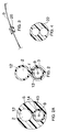
- Fig. 2 represents a cross-sectional view in the distal direction showing how lumens 2 and 3 relate to one another and how pushing wire 5 can be positioned within lumen 3.
- Lumen walls 12 and 13 can each have a thickness of from about 12.7 ⁇ m to 76.2 ⁇ m (0.5 to 3 mil) and may be of different thicknesses.
- Fig. 2a represents an alternative embodiment wherein the external aspect of the catheter is more rounded.
- the lumen walls 12 and 13 are comprised of materials conventional to balloon dilatation catheters. Suitable materials include polyolefins such as polyethylene, polyethylene terepthalate, urethane, polyester, and various copolymers thereof.
- Pushing wire 5 can be made from any rigid, medically acceptable material suitable for such use, including, but not limited to wires or hypotubes comprised of stainless steel or other rigid materials.
- the construction according to the invention leads to flexibility in product design.
- the choice of pushing wire or its absence allows the designer to impart various features to the catheter in the form of various flexibility and pushability combinations.
- a hollow pushing wire would facilitate infusion of fluids, drugs, and/or contrast media through the catheter into the distal vasculature.
- the catheter 1 may have a third coextensive lumen that would similarly facilitate infusion of liquids, drugs and/or contrast media or even provide an alternative location for pushing wire 5.
- a lubricious coating or a section of thin tubing 14 of lubricious material is sealed into lumen 3.
- a lubricious coating or a section of thin tubing 14 of lubricious material is sealed into lumen 3.
- materials suitable for this purpose such as polytetrafluoroethylene (available as TEFLON® from duPont), polysiloxanes, etc.
- the tubing section 14 can hold the pushing wire 5 in position.
- a slitting means 20 may be removedly mounted proximally on guidewire 9. Then, as the catheter 1 is withdrawn with guidewire 9 remaining in position, for example, with its distal end across a stenotic lesion, lumen 3 engages the slitter means 20, lumen 3 is slit, and catheter 1 is separated from guidewire 9. This would eliminate the requirement for the operator to change hands as catheter 1 is removed and would facilitate quick removal of the catheter 1 from the patient. In addition, since the balloon is not slit, it can be reinflated outside the patient to verify the inflated diameter.
- the catheter 1 may have visual length markings 30 along its shaft that would enable the operator to predict when the catheter 1 would exit the guiding catheter into the vasculature. This would reduce the fluoroscope time.
- the preferred design would put the markings directly on pushing wire 5 (heat shrink tubing rings, inks, paints, etc.). Since pushing wire 5 is substantially positioned within the guidewire lumen 3, the markings would not be exposed to the patient (i.e., markings would not come off, and materials which could be toxic if exposed may be used). If a thin tubing 14 is used within lumen 3, the markings could alternately be placed within or, preferably, around tubing 14.
- Double lumen workpiece 21 can be prepared by methods well known to those skilled in the art. In a preferred method workpiece 21 is prepared by sealingly clamping the distal end of double lumen extruded tubing 22, a cross-section of which is shown in Fig. 4, and applying heat and pressure to blow the extruded tubing 22 to form workpiece 21.
- Lubricious tubing 14 is inserted into lumen 3. Heat is applied to cause lumen 3 to shrink such that lubricious tubing 14 is positively engaged within lumen 3.
- pushing wire 5 is inserted into lumen 3 prior to shrinking between tubing 14 and lumen wall 13. When lumen 3 shrinks, pushing wire 5 and lubricous tubing 14 are fixedly constrained within lumen 3.
- a removable hub means 24 is in fluid communication with the proximal opening 10 of lumen 3, as shown in Fig. 8.
- hub means 24 facilitates infusion of fluids or drugs through lumen 3.
- hub means 24 may extend distally into lumen 3 along guidewire 9.
- tubing 14 were to extend proximally from opening 10, hub means 24 may be adjoined to and in fluid communication with tubing 14.
- Hub means 24 is removedly bonded, joined, or attached to either distal opening 10 or tubing 14. Therefore, when hub means 24 is to be removed, such as when catheter 1 is to be removed, removal of hub means 24 is accomplished by pulling hub means 24 in the proximal direction over the proximal end of guidewire 9.
- An advantage of the design and preparation according to the invention is that the catheter can be of integral design and multiple bonding steps can be avoided.
- the balloon and both lumens can be formed from a single piece. This design permits improvements in manufacturing yields, quality, and reliability due to simplified construction.
- Guidewire 9 may be a conventional guidewire, preferably a spring guidewire, as is well known. Typical guidewires are shown in U.S. Patents Nos. 4,757,827, 4,815,478, 4,813,434, 4,619,274, 4,554,929, 4,545,390, 4,538,622, 3,906,938, 3,973,556, and 4,719,924.
- the shaft of guidewire 9 could be solid or hollow, such as a hypotube, with an open distal end, to facilitate drug infusion.
- a guiding catheter is inserted into the coronary artery in a conventional manner.
- the guidewire 9 is then introduced into the balloon dilatation catheter 1 by either a back loading technique where the proximal extremity of the guidewire 9 is inserted backwardly through opening 11 of balloon dilatation catheter 1, or a forward loading technique, where the distal extremity of the guidewire 9 is inserted in proximal opening 10.
- the guidewire 9 is advanced proximally until the proximal extremity of the guidewire is near the proximal extremity of the dilatation catheter 1 and so that the distal extremity of the guidewire 9 with its flexible or floppy tip 23 protrudes at least partially from the distal extremity of the balloon dilatation catheter.
- a guidewire gripping means, or torquer, such as a slitter 20, is now attached to the guidewire 9 near its proximal extremity, and the guidewire 9 is then advanced ahead of the balloon dilatation catheter 1 until it enters the arterial vessel of the patient.
- the balloon dilatation catheter 1 is held stable by the fingers of the hand while the guidewire 9 is being advanced.
- the positioning of the guidewire 9 in the desired arterial vessel can be observed under a fluoroscope by using x-ray or fluoroscopic techniques well known to those skilled in the art.
- the torquer can be utilized to rotate the guidewire 9 to facilitate positioning of its distal tip in the desired arterial vessel so that the distal extremity of the guidewire can be advanced into the stenosis which it is desired to open or enlarge.
- the guidewire 9 As soon as the guidewire 9 is in the desired location, it can be held stationary by two fingers of the hand and then the balloon dilatation catheter 1 is advanced over the guidewire until the deflated balloon 4 is across the desired lesion or stenosis. If any difficulty is encountered by the person conducting the procedure in introducing the balloon dilatation catheter so that the balloon 4 resists crossing the lesions or stenosis, the guidewire 9 can be retracted slightly. The operator then can observe under the fluoroscope to see that the tip of the guidewire 9 is wiggling in the bloodstream indicating that it is free to move in the bloodstream. Then the operator can grasp both the guidewire and the dilatation catheter in one hand and advance them as a unit so that they can cross the stenosis as a unit.
- the balloon 4 When the balloon 4 has crossed the stenosis or lesion, the balloon 4 can be inflated in a conventional manner by introducing a radiopaque contrast liquid through the lumen 2. After the inflation has occurred and the desired operation has been performed by enlarging the opening in the stenosis, the balloon dilatation catheter 1 can be removed very rapidly by holding the slitting means 20 stationary and pulling back catheter 1 such that the guidewire lumen 3 is slit and the catheter is separated from the guidewire. As soon as the balloon dilatation catheter 1 has been removed from the guiding catheter, another injection of radiographic contrast liquid can be introduced through the guiding catheter to observe whether or not the balloon dilatation procedure which has been performed on the lesion or stenosis to the satisfaction of the person performing the procedure. With the guidewire still in place, access to the lesion is maintained.
Landscapes
- Health & Medical Sciences (AREA)
- Heart & Thoracic Surgery (AREA)
- Life Sciences & Earth Sciences (AREA)
- Anesthesiology (AREA)
- Child & Adolescent Psychology (AREA)
- Biophysics (AREA)
- Pulmonology (AREA)
- Engineering & Computer Science (AREA)
- Vascular Medicine (AREA)
- Biomedical Technology (AREA)
- Hematology (AREA)
- Animal Behavior & Ethology (AREA)
- General Health & Medical Sciences (AREA)
- Public Health (AREA)
- Veterinary Medicine (AREA)
- Media Introduction/Drainage Providing Device (AREA)
Claims (10)
- Cathéter à ballonnet de dilatation (1) qui comprend :une tige de cathéter (6) qui définit une première lumière de gonflage (2) et une deuxième lumière (3), ladite tige de cathéter ayant des parties proximale et distale, etun ballonnet de dilatation gonflable (4) relié de façon étanche à ladite tige de cathéter (6),dans lequel la première lumière (2) se prolonge sur toute la longueur de ladite tige de cathéter et possède des extrémités distale et proximale, ladite extrémité distale s'ouvrant dans l'intérieur dudit ballonnet de dilatation gonflable (4) et étant en communication fluide avec celui-ci etdans lequel la deuxième lumière (3) possède des parties proximale et distale et une paroi intérieure (8), ladite partie proximale de ladite deuxième lumière (3) s'étendant depuis une extrémité proximale ouverte, en étant distale par rapport à l'extrémité proximale de ladite première lumière, ladite section distale de ladite deuxième lumière étant extérieure audit ballonnet de dilatation gonflable, ladite extrémité distale de ladite deuxième lumière étant ouverte (11), ladite deuxième lumière contenant un matériau lubrifiant sous la forme d'un tuyau disposé de manière concentrique, et ladite deuxième lumière étant capable de recevoir un fil guide (9) selon un emboítement coulissant.
- Cathéter selon la revendication 1, dans lequel la lumière de gonflage contient un fil de poussée (5) ayant des extrémités proximale et distale.
- Cathéter selon la revendication 1, dans lequel la deuxième lumière contient un fil de poussée (5) ayant des extrémités proximale et distale.
- Cathéter selon la revendication 2 ou 3, dans lequel le fil de poussée (5) a son extrémité distale qui est disposée de façon proximale ou adjacente au ballonnet (4).
- Cathéter selon la revendication 2 ou 3, dans lequel le fil de poussée (5) se prolonge à travers le ballonnet (4).
- Cathéter selon la revendication 2 ou 3, dans lequel l'extrémité distale du fil de poussée (5) est effilée.
- Cathéter selon la revendication 3 ou l'une quelconque des revendications 4 à 6 dépendantes de la revendication 3, dans lequel le fil de poussée (5) est maintenu en position par le tuyau lubrifiant et la paroi de la deuxième lumière.
- Système de cathéter à ballonnet de dilatation qui comprend un cathéter à ballonnet de dilatation selon la revendication 1 et un fil guide (9) possédant des extrémités distale et proximale, l'extrémité distale du fil guide (9) étant reçue dans la deuxième lumière (3) du cathéter à ballonnet de dilatation selon un emboítement coulissant.
- Système selon la revendication 8, dans lequel le fil guide (9) possède un dispositif de fendage (20) pour fendre la deuxième lumière.
- Système selon la revendication 9, dans lequel le dispositif de fendage (20) fait office également de moyen pour saisir le fil guide.
Applications Claiming Priority (3)
| Application Number | Priority Date | Filing Date | Title |
|---|---|---|---|
| US08/087,428 US5520647A (en) | 1993-07-02 | 1993-07-02 | Rapid withdrawal catheter |
| PCT/US1994/007407 WO1995001202A1 (fr) | 1993-07-02 | 1994-07-01 | Catheter a retrait rapide |
| US87428 | 2002-03-01 |
Publications (3)
| Publication Number | Publication Date |
|---|---|
| EP0707501A1 EP0707501A1 (fr) | 1996-04-24 |
| EP0707501A4 EP0707501A4 (fr) | 1997-01-22 |
| EP0707501B1 true EP0707501B1 (fr) | 2000-02-16 |
Family
ID=22205135
Family Applications (1)
| Application Number | Title | Priority Date | Filing Date |
|---|---|---|---|
| EP94921437A Expired - Lifetime EP0707501B1 (fr) | 1993-07-02 | 1994-07-01 | Catheter a retrait rapide |
Country Status (7)
| Country | Link |
|---|---|
| US (1) | US5520647A (fr) |
| EP (1) | EP0707501B1 (fr) |
| JP (1) | JPH08511977A (fr) |
| AU (1) | AU679089B2 (fr) |
| CA (1) | CA2166463C (fr) |
| DE (1) | DE69423046T2 (fr) |
| WO (1) | WO1995001202A1 (fr) |
Families Citing this family (35)
| Publication number | Priority date | Publication date | Assignee | Title |
|---|---|---|---|---|
| US5752932A (en) * | 1993-04-29 | 1998-05-19 | Scimed Life Systems, Inc. | Intravascular catheter with a recoverable guide wire lumen and method of use |
| US5667493A (en) * | 1994-12-30 | 1997-09-16 | Janacek; Jaroslav | Dilation catheter |
| FR2736270B1 (fr) * | 1995-07-06 | 1998-01-09 | Nycomed Lab Sa | Catheter de dilatation du type guide sur un fil |
| US5690642A (en) | 1996-01-18 | 1997-11-25 | Cook Incorporated | Rapid exchange stent delivery balloon catheter |
| DE69723137T2 (de) * | 1996-03-18 | 2004-05-27 | Ashiya, Hiroaki | Catheteranordnung |
| JP3999830B2 (ja) * | 1996-06-10 | 2007-10-31 | 株式会社ヴァーユ | バルーンカテーテル |
| US6056719A (en) * | 1998-03-04 | 2000-05-02 | Scimed Life Systems, Inc. | Convertible catheter incorporating a collapsible lumen |
| US6780199B2 (en) * | 1998-05-15 | 2004-08-24 | Advanced Cardiovascular Systems, Inc. | Enhanced stent delivery system |
| US20020007145A1 (en) | 1998-10-23 | 2002-01-17 | Timothy Stivland | Catheter having improved bonding region |
| US6290673B1 (en) * | 1999-05-20 | 2001-09-18 | Conor Medsystems, Inc. | Expandable medical device delivery system and method |
| SI1255506T1 (en) | 2000-02-18 | 2004-02-29 | E.V.R. Endovascular Researches S.A. | Endolumenal device for delivering and deploying an endolumenal expandable prosthesis |
| US7150737B2 (en) | 2001-07-13 | 2006-12-19 | Sci/Med Life Systems, Inc. | Methods and apparatuses for navigating the subarachnoid space |
| US7455666B2 (en) | 2001-07-13 | 2008-11-25 | Board Of Regents, The University Of Texas System | Methods and apparatuses for navigating the subarachnoid space |
| US20030093105A1 (en) * | 2001-07-13 | 2003-05-15 | Scimed Life Systems, Inc. | Guide catheter for introduction into the subarachnoid space and methods of use thereof |
| US7011647B2 (en) * | 2001-07-13 | 2006-03-14 | Scimed Life Systems, Inc. | Introducer sheath |
| AU2002350164A1 (en) * | 2001-11-08 | 2003-05-19 | William D. Hare | Rapid exchange catheter with stent deployment, therapeutic infusion, and lesion sampling features |
| US20060047261A1 (en) * | 2004-06-28 | 2006-03-02 | Shailendra Joshi | Intra-arterial catheter for drug delivery |
| US20060135940A1 (en) * | 2003-01-06 | 2006-06-22 | The Trustees Of Columbia | Programmed pulsed infusion methods and devices |
| WO2004093968A1 (fr) * | 2003-04-24 | 2004-11-04 | Invatec S.R.L. | Structure à ballonnet et cathéter à ballonnet |
| US8252014B2 (en) | 2004-03-03 | 2012-08-28 | Innovational Holdings Llc. | Rapid exchange balloon catheter with braided shaft |
| US9050437B2 (en) * | 2004-03-04 | 2015-06-09 | YMED, Inc. | Positioning device for ostial lesions |
| US7766951B2 (en) * | 2004-03-04 | 2010-08-03 | Y Med, Inc. | Vessel treatment devices |
| US7780715B2 (en) * | 2004-03-04 | 2010-08-24 | Y Med, Inc. | Vessel treatment devices |
| US7753951B2 (en) * | 2004-03-04 | 2010-07-13 | Y Med, Inc. | Vessel treatment devices |
| US8177760B2 (en) | 2004-05-12 | 2012-05-15 | C. R. Bard, Inc. | Valved connector |
| JP2009509622A (ja) * | 2005-10-03 | 2009-03-12 | ワイ メッド インク | 血管治療装置 |
| US8486025B2 (en) * | 2006-05-11 | 2013-07-16 | Ronald J. Solar | Systems and methods for treating a vessel using focused force |
| US7901378B2 (en) * | 2006-05-11 | 2011-03-08 | Y-Med, Inc. | Systems and methods for treating a vessel using focused force |
| EP2485638B1 (fr) | 2009-10-07 | 2016-11-30 | Endophys Holdings, LLC | Dispositif médical de détection de pression |
| JP5728779B2 (ja) * | 2010-07-23 | 2015-06-03 | 国立大学法人大阪大学 | 血管内止血カテーテル |
| JP6039199B2 (ja) * | 2012-03-12 | 2016-12-07 | 株式会社グッドマン | カテーテル |
| US10595820B2 (en) * | 2012-12-20 | 2020-03-24 | Philips Image Guided Therapy Corporation | Smooth transition catheters |
| US9254208B2 (en) | 2013-03-14 | 2016-02-09 | Thomas Ischinger | Oblique stent |
| US9937333B2 (en) | 2015-09-01 | 2018-04-10 | Thomas Ischinger | Balloon catheter for treatment of a vessel at a bifurcation |
| JPWO2023157533A1 (fr) * | 2022-02-18 | 2023-08-24 |
Family Cites Families (9)
| Publication number | Priority date | Publication date | Assignee | Title |
|---|---|---|---|---|
| DE3420455C1 (de) * | 1984-06-01 | 1985-05-15 | Peter Dr.-Ing. 7889 Grenzach-Wyhlen Osypka | Trenneinrichtung fuer eine Einfuehrungshuelse |
| DE3442736C2 (de) * | 1984-11-23 | 1987-03-05 | Tassilo Dr.med. 7800 Freiburg Bonzel | Dilatationskatheter |
| US4983167A (en) * | 1988-11-23 | 1991-01-08 | Harvinder Sahota | Balloon catheters |
| US5180367A (en) * | 1989-09-06 | 1993-01-19 | Datascope Corporation | Procedure and balloon catheter system for relieving arterial or veinal restrictions without exchanging balloon catheters |
| US5141494A (en) * | 1990-02-15 | 1992-08-25 | Danforth Biomedical, Inc. | Variable wire diameter angioplasty dilatation balloon catheter |
| US5395332A (en) * | 1990-08-28 | 1995-03-07 | Scimed Life Systems, Inc. | Intravascualr catheter with distal tip guide wire lumen |
| US5167233A (en) * | 1991-01-07 | 1992-12-01 | Endosonics Corporation | Dilating and imaging apparatus |
| EP0595308B1 (fr) * | 1992-10-30 | 2001-12-12 | Cordis Corporation | Cathéter à échange rapide |
| US5409458A (en) * | 1993-11-10 | 1995-04-25 | Medtronic, Inc. | Grooved balloon for dilatation catheter |
-
1993
- 1993-07-02 US US08/087,428 patent/US5520647A/en not_active Expired - Lifetime
-
1994
- 1994-07-01 JP JP7503646A patent/JPH08511977A/ja not_active Expired - Lifetime
- 1994-07-01 EP EP94921437A patent/EP0707501B1/fr not_active Expired - Lifetime
- 1994-07-01 WO PCT/US1994/007407 patent/WO1995001202A1/fr not_active Ceased
- 1994-07-01 CA CA002166463A patent/CA2166463C/fr not_active Expired - Lifetime
- 1994-07-01 AU AU72166/94A patent/AU679089B2/en not_active Expired
- 1994-07-01 DE DE69423046T patent/DE69423046T2/de not_active Expired - Lifetime
Also Published As
| Publication number | Publication date |
|---|---|
| DE69423046T2 (de) | 2000-08-03 |
| AU7216694A (en) | 1995-01-24 |
| EP0707501A1 (fr) | 1996-04-24 |
| US5520647A (en) | 1996-05-28 |
| WO1995001202A1 (fr) | 1995-01-12 |
| EP0707501A4 (fr) | 1997-01-22 |
| CA2166463A1 (fr) | 1995-01-12 |
| DE69423046D1 (de) | 2000-03-23 |
| AU679089B2 (en) | 1997-06-19 |
| JPH08511977A (ja) | 1996-12-17 |
| CA2166463C (fr) | 2003-01-07 |
Similar Documents
| Publication | Publication Date | Title |
|---|---|---|
| AU679089B2 (en) | Rapid withdrawal catheter | |
| US5531690A (en) | Rapid exchange catheter | |
| US5315747A (en) | Method of preparing a balloon dilatation catheter | |
| EP0773810B1 (fr) | Catheter telescopique | |
| EP0564894B1 (fr) | Système d'échange rapide de cathéter | |
| US5334154A (en) | Perfusion type dilatation catheter having perfusion ports with depressed proximal edges | |
| CA2070914C (fr) | Catheter utilisable pour la dilatation et fil de guidage | |
| US5980486A (en) | Rapidly exchangeable coronary catheter | |
| US5728067A (en) | Rapidly exchangeable coronary catheter | |
| EP0416734B1 (fr) | Cathéter guide et fils de guidage pour effecteur un échange rapide de cathéter | |
| EP0715531B1 (fr) | Catheter a dilatation avec ballon excentrique | |
| US5342297A (en) | Bailout receptacle for angioplasty catheter | |
| US5040548A (en) | Angioplasty mehtod | |
| US6447501B1 (en) | Enhanced stent delivery system | |
| EP0371486A1 (fr) | Cathéter vasculaire avec fil de guidage fixé de façon détachable | |
| EP0620023A1 (fr) | Cathéter avec fenêtre et méthode emploi | |
| AU4080999A (en) | Enhanced balloon dilatation system | |
| WO1993020880A1 (fr) | Catheter extractible destine a l'angioplastie a fil de torsion fixe | |
| EP0595308B1 (fr) | Cathéter à échange rapide | |
| AU707509B2 (en) | Method of exchanging intravascular devices |
Legal Events
| Date | Code | Title | Description |
|---|---|---|---|
| PUAI | Public reference made under article 153(3) epc to a published international application that has entered the european phase |
Free format text: ORIGINAL CODE: 0009012 |
|
| 17P | Request for examination filed |
Effective date: 19960201 |
|
| AK | Designated contracting states |
Kind code of ref document: A1 Designated state(s): DE FR GB IT NL |
|
| A4 | Supplementary search report drawn up and despatched |
Effective date: 19961203 |
|
| AK | Designated contracting states |
Kind code of ref document: A4 Designated state(s): DE FR GB IT NL |
|
| GRAG | Despatch of communication of intention to grant |
Free format text: ORIGINAL CODE: EPIDOS AGRA |
|
| GRAG | Despatch of communication of intention to grant |
Free format text: ORIGINAL CODE: EPIDOS AGRA |
|
| GRAH | Despatch of communication of intention to grant a patent |
Free format text: ORIGINAL CODE: EPIDOS IGRA |
|
| 17Q | First examination report despatched |
Effective date: 19990712 |
|
| GRAH | Despatch of communication of intention to grant a patent |
Free format text: ORIGINAL CODE: EPIDOS IGRA |
|
| GRAA | (expected) grant |
Free format text: ORIGINAL CODE: 0009210 |
|
| AK | Designated contracting states |
Kind code of ref document: B1 Designated state(s): DE FR GB IT NL |
|
| REF | Corresponds to: |
Ref document number: 69423046 Country of ref document: DE Date of ref document: 20000323 |
|
| ITF | It: translation for a ep patent filed | ||
| ET | Fr: translation filed | ||
| PLBE | No opposition filed within time limit |
Free format text: ORIGINAL CODE: 0009261 |
|
| STAA | Information on the status of an ep patent application or granted ep patent |
Free format text: STATUS: NO OPPOSITION FILED WITHIN TIME LIMIT |
|
| 26N | No opposition filed | ||
| REG | Reference to a national code |
Ref country code: GB Ref legal event code: IF02 |
|
| PGFP | Annual fee paid to national office [announced via postgrant information from national office to epo] |
Ref country code: GB Payment date: 20130626 Year of fee payment: 20 |
|
| PGFP | Annual fee paid to national office [announced via postgrant information from national office to epo] |
Ref country code: DE Payment date: 20130626 Year of fee payment: 20 Ref country code: NL Payment date: 20130710 Year of fee payment: 20 |
|
| PGFP | Annual fee paid to national office [announced via postgrant information from national office to epo] |
Ref country code: FR Payment date: 20130724 Year of fee payment: 20 |
|
| PGFP | Annual fee paid to national office [announced via postgrant information from national office to epo] |
Ref country code: IT Payment date: 20130712 Year of fee payment: 20 |
|
| REG | Reference to a national code |
Ref country code: DE Ref legal event code: R071 Ref document number: 69423046 Country of ref document: DE |
|
| REG | Reference to a national code |
Ref country code: NL Ref legal event code: V4 Effective date: 20140701 |
|
| REG | Reference to a national code |
Ref country code: GB Ref legal event code: PE20 Expiry date: 20140630 |
|
| PG25 | Lapsed in a contracting state [announced via postgrant information from national office to epo] |
Ref country code: GB Free format text: LAPSE BECAUSE OF EXPIRATION OF PROTECTION Effective date: 20140630 |
|
| PG25 | Lapsed in a contracting state [announced via postgrant information from national office to epo] |
Ref country code: DE Free format text: LAPSE BECAUSE OF EXPIRATION OF PROTECTION Effective date: 20140702 |