EP0707786A1 - Arrangement de montage pour lame à couper le fil d'une tondeuse à fil de coupe flexible - Google Patents
Arrangement de montage pour lame à couper le fil d'une tondeuse à fil de coupe flexible Download PDFInfo
- Publication number
- EP0707786A1 EP0707786A1 EP95307440A EP95307440A EP0707786A1 EP 0707786 A1 EP0707786 A1 EP 0707786A1 EP 95307440 A EP95307440 A EP 95307440A EP 95307440 A EP95307440 A EP 95307440A EP 0707786 A1 EP0707786 A1 EP 0707786A1
- Authority
- EP
- European Patent Office
- Prior art keywords
- blade
- cut
- housing
- slot
- guard
- Prior art date
- Legal status (The legal status is an assumption and is not a legal conclusion. Google has not performed a legal analysis and makes no representation as to the accuracy of the status listed.)
- Withdrawn
Links
- 238000000034 method Methods 0.000 claims description 7
- 238000009966 trimming Methods 0.000 claims description 7
- 230000013011 mating Effects 0.000 claims 2
- 230000000717 retained effect Effects 0.000 claims 1
- 238000004519 manufacturing process Methods 0.000 description 12
- 244000025254 Cannabis sativa Species 0.000 description 1
- 241000196324 Embryophyta Species 0.000 description 1
- 238000010276 construction Methods 0.000 description 1
- 238000012986 modification Methods 0.000 description 1
- 230000004048 modification Effects 0.000 description 1
- 230000002028 premature Effects 0.000 description 1
- 230000002035 prolonged effect Effects 0.000 description 1
- 230000003014 reinforcing effect Effects 0.000 description 1
- 230000000284 resting effect Effects 0.000 description 1
Images
Classifications
-
- A—HUMAN NECESSITIES
- A01—AGRICULTURE; FORESTRY; ANIMAL HUSBANDRY; HUNTING; TRAPPING; FISHING
- A01D—HARVESTING; MOWING
- A01D34/00—Mowers; Mowing apparatus of harvesters
- A01D34/01—Mowers; Mowing apparatus of harvesters characterised by features relating to the type of cutting apparatus
- A01D34/412—Mowers; Mowing apparatus of harvesters characterised by features relating to the type of cutting apparatus having rotating cutters
- A01D34/416—Flexible line cutters
Definitions
- This invention relates to string trimmers, and more particularly to a string trimmer including a line cut-off blade which is captively held within a slot in a portion of a guard of the string trimmer without the use of rivets, threaded screws or other like fasteners when the string trimmer is assembled.
- String trimmers are used in a wide variety of applications to trim vegetation such as grass, weeds, etc. in areas closely adjacent walls of buildings, fences, shrubs,' etc. where other forms of vegetation cutters such as lawn mowers have difficulty cutting or are unable to cut.
- Such string trimmers typically include a handle portion which is graspable with one or both hands of the operator, a neck or intermediate portion and a base portion.
- Each of the handle assembly, neck portion and base portion are typically molded from plastic using a two-piece, clam shell-like construction arrangement.
- the string trimmer is assembled by securing two halves of the housing together, which together form the housing for the entire string trimmer.
- a line cut-off blade is typically secured in a guard portion of the housing.
- the guard portion is typically integrally formed with the base assembly of the string trimmer from plastic and protrudes generally transversely of the base assembly to act as a partial guard for the rotating cutting line.
- the cut-off blade is typically secured via rivets or threaded screws to a portion of the plastic guard during assembly of the string trimmer at the factory or other like facility.
- a string trimmer apparatus which includes a guard having a cut-off blade positioned therein in a manner which does not require the use of rivets or other threaded screws to maintain the cut-off blade secured to the guard.
- a string trimmer apparatus having a two-piece housing assembly wherein a first half of the housing assembly may be molded from a suitably strong plastic to form a slot into which a line cut-off blade may be slidably inserted. It is a further object to provide a second housing portion is securable to the first housing portion in a manner which causes a cutting edge of the line cut-off blade to dig into or "bite" into a surface of the second housing portion. In this manner the line cut-off blade could be captively maintained within the slot once the two housing halves are secured together without the need for rivets or threaded screws.
- the above and other objects are accomplished by a string trimmer apparatus having a line cut-off blade mounting arrangement in accordance with a preferred embodiment of the present invention.
- the string trimmer apparatus -includes a base portion which is constructed in two halves in a clam shell-like configuration. Each housing portion includes a guard portion formed therewith. When the two housing halves are secured together a guard is formed which protrudes generally transversely of the base portion.
- the guard portion of a first one of the housing halves includes a lip portion which includes a slot.
- the slot is dimensioned to be able to slidably receive therein a major portion of a line cut-off blade.
- the second housing portion when secured to the first housing portion, thus captively maintains the line cut-off blade securely within the slot without the need for rivets, threaded screws or the like. Accordingly, the overall simplicity of manufacture of the string trimmer is increased since the added step of riveting or likewise securing the line cut-off blade to a portion of the guard is eliminated. This further reduces the overall cost of manufacture of the line trimmer since no rivets, threaded screws or the like are required to secure the line cut-off blade to the guard.
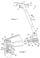
- the string trimmer apparatus 10 generally includes a handle assembly 12, a neck or intermediate assembly 14 and a base assembly 16.
- Each of the handle assembly 12, intermediate assembly 14 and base assembly 16 are constructed in a two-piece, clam shell-like configuration.
- the handle assembly 12 is comprised of two half portions 12a and 12b
- the intermediate assembly 14 is comprised of two half portions 14a and 14b
- the base assembly 16 is comprised of two half portions 16a and 16b.
- a trigger 18 is included for turning on and off a motor disposed within the base assembly 16.
- the intermediate assembly 14 and base assembly 16 are each assembled by securing their respective component halves 14a, 14b and 16a, 16b together via threaded screws or other like fasteners.
- the base assembly 16 includes a guard 20 which protrudes generally transversely of a main body portion 22 of the base assembly 16.
- the guard 20 is comprised of a first guard portion 24a and a second guard portion 24b.
- Each of the guard portions 24a and 24b include a lip portion 26a and 26b.
- a cutting blade is secured to a lip portion of the guard by conventional rivets, threaded screws or the like such that when the cutting line 28 is driven rotationally, the cutting blade will cut the cutting line 28 if the length of the cutting line 28 extends past the lip portion of the guard 20.
- this mounting arrangement for the line cut-off blade still requires the added manufacturing step of securing the line cut-off blade to the lip portion of the guard via one or more rivets or other threaded screws.
- this introduces an additional manufacturing step which increases the overall cost of manufacture of the string trimmer.
- the cost of manufacture is further increased by the requirement of additional components parts (i.e., the rivets or threaded screws) which are required to secure the line cut-off blade to the guard.
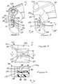
- the housing half 16b includes a boss portion 30 having a bore 32 therein.
- the guard portion 26b includes an outer portion 34 spaced apart from an inner portion 36 in part by a reinforcing rib 37 which is integrally formed with the outer portion 34 and the inner portion 36.
- a pair of raised shoulder portions 38 are also integrally formed with the outer portion 34 and are of a predetermined height such that an upper edge surface 40 of each is spaced apart from an inner surface 42 of the inner portion 36 to form a slot 44.
- the slot 44 has an overall height which is sufficient to allow a line cut-off blade to be inserted therein.
- the inner portion 36 includes a sloped wall portion 46 having an upper edge surface 48.
- the distance between the upper edge surface 48 and an upper surface 50 of each raised shoulder portion 38 is such that when a line cut-off blade is inserted therein a major portion of the blade is held within the slot 44 in a secure manner.
- the second housing half 16b is shown with a line cut-off blade 52 inserted within the slot 44.
- the major portion of the body of the line cut-off blade 52 is disposed within the slot 44 such that only a cutting edge portion 54 of the blade 52 is exposed above the slot 44.
- a bottom edge portion 56 of the line cut-off blade 52 rests against the upper edge surface 48 of the sloped wall portion 46 when the line cut-off blade 52 is fully inserted within the slot 44.
- the slot 44 in the second housing portion 16b is easily formed with a suitable mold as an integral portion of the second housing portion 16b.
- the additional assembly step of manually riveting the line cut-off blade 52 to a portion of the guard is eliminated.
- the need for rivets or other threaded screws to secure the line cut-off blade is eliminated.
- the arrangement disclosed herein for securing the line cut-off blade represents a significant improvement in the ease of manufacture of the string trimmer apparatus 10 as well as helping to reduce the overall cost of manufacture of the string trimmer apparatus. Since rivets or other threaded screws are not required to hold the line cut-off blade 52 to the guard, there is little chance that the line cut-off blade will become loose relative to the guard after prolonged use of the string trimmer apparatus 10.
- the lip portion 26b of the guard portion 24b includes the sloped wall portion 46 which guides a freshly cut end of the cutting line 28 (shown in Figure 4) over an inner surface 60 of the inner portion 36.
- a sloped edge portion 47 of the inner portion 36 also helps to guide the cutting line 28 toward the cutting edge 54 of the cut-off blade 52 immediately after a new section of cutting line has been advanced. In this manner, once a trimming line is freshly cut by the line cut-off blade 52, the trimming line will not abruptly bump against a shoulder portion or other corner which would otherwise be formed if the sloped wall portion 46 were not included. This feature further helps to prevent premature wear of the inner surface 60 of the lip portion 26b since the cutting line 28 gradually rides up the sloped wall portion 46 without encountering any abrupt shoulder portions or protrusions.
Landscapes
- Life Sciences & Earth Sciences (AREA)
- Environmental Sciences (AREA)
- Harvester Elements (AREA)
- Knives (AREA)
Applications Claiming Priority (2)
| Application Number | Priority Date | Filing Date | Title |
|---|---|---|---|
| US32673094A | 1994-10-20 | 1994-10-20 | |
| US326730 | 1994-10-20 |
Publications (1)
| Publication Number | Publication Date |
|---|---|
| EP0707786A1 true EP0707786A1 (fr) | 1996-04-24 |
Family
ID=23273445
Family Applications (1)
| Application Number | Title | Priority Date | Filing Date |
|---|---|---|---|
| EP95307440A Withdrawn EP0707786A1 (fr) | 1994-10-20 | 1995-10-19 | Arrangement de montage pour lame à couper le fil d'une tondeuse à fil de coupe flexible |
Country Status (3)
| Country | Link |
|---|---|
| EP (1) | EP0707786A1 (fr) |
| CA (1) | CA2160843A1 (fr) |
| MX (1) | MX9504459A (fr) |
Cited By (3)
| Publication number | Priority date | Publication date | Assignee | Title |
|---|---|---|---|---|
| EP2554040A1 (fr) * | 2011-08-04 | 2013-02-06 | Makita Corporation | Débroussailleuse |
| CN102907209A (zh) * | 2011-08-04 | 2013-02-06 | 株式会社牧田 | 割灌机 |
| EP3092884A3 (fr) * | 2015-05-15 | 2017-04-19 | Black & Decker Inc. | Tondeuse à fil avec ensemble de protection réglable |
Families Citing this family (1)
| Publication number | Priority date | Publication date | Assignee | Title |
|---|---|---|---|---|
| CN113057035A (zh) * | 2021-03-26 | 2021-07-02 | 张志芳 | 一种园林管理用枝叶修剪器 |
Citations (7)
| Publication number | Priority date | Publication date | Assignee | Title |
|---|---|---|---|---|
| FR2372585A2 (fr) * | 1971-12-13 | 1978-06-30 | Weed Eater | Appareil de coupe de vegetaux |
| US4362074A (en) * | 1979-08-17 | 1982-12-07 | Emerson Electric Co. | Method for cutting vegetation |
| EP0131666A1 (fr) * | 1983-07-18 | 1985-01-23 | McCulloch Corporation | Tondeuse à fil de coupe flexible |
| GB2155299A (en) * | 1982-01-08 | 1985-09-25 | Black & Decker Inc | Improvements in or relating to vegetation cutters and components therefor |
| DE8804699U1 (de) * | 1988-04-09 | 1988-07-21 | Stihl, Andreas, 7050 Waiblingen | Freischneidegerät mit einer Schutzvorrichtung |
| US5060383A (en) * | 1990-08-06 | 1991-10-29 | Ratkiewich Richard H | Vegetation cutter |
| DE4237357A1 (de) * | 1992-11-05 | 1994-05-11 | Stihl Maschf Andreas | Schutzschild für ein Freischneidegerät |
-
1995
- 1995-10-18 CA CA 2160843 patent/CA2160843A1/fr not_active Abandoned
- 1995-10-19 EP EP95307440A patent/EP0707786A1/fr not_active Withdrawn
- 1995-10-20 MX MX9504459A patent/MX9504459A/es unknown
Patent Citations (7)
| Publication number | Priority date | Publication date | Assignee | Title |
|---|---|---|---|---|
| FR2372585A2 (fr) * | 1971-12-13 | 1978-06-30 | Weed Eater | Appareil de coupe de vegetaux |
| US4362074A (en) * | 1979-08-17 | 1982-12-07 | Emerson Electric Co. | Method for cutting vegetation |
| GB2155299A (en) * | 1982-01-08 | 1985-09-25 | Black & Decker Inc | Improvements in or relating to vegetation cutters and components therefor |
| EP0131666A1 (fr) * | 1983-07-18 | 1985-01-23 | McCulloch Corporation | Tondeuse à fil de coupe flexible |
| DE8804699U1 (de) * | 1988-04-09 | 1988-07-21 | Stihl, Andreas, 7050 Waiblingen | Freischneidegerät mit einer Schutzvorrichtung |
| US5060383A (en) * | 1990-08-06 | 1991-10-29 | Ratkiewich Richard H | Vegetation cutter |
| DE4237357A1 (de) * | 1992-11-05 | 1994-05-11 | Stihl Maschf Andreas | Schutzschild für ein Freischneidegerät |
Cited By (6)
| Publication number | Priority date | Publication date | Assignee | Title |
|---|---|---|---|---|
| EP2554040A1 (fr) * | 2011-08-04 | 2013-02-06 | Makita Corporation | Débroussailleuse |
| CN102907209A (zh) * | 2011-08-04 | 2013-02-06 | 株式会社牧田 | 割灌机 |
| CN102907209B (zh) * | 2011-08-04 | 2015-07-08 | 株式会社牧田 | 割灌机 |
| EP3092884A3 (fr) * | 2015-05-15 | 2017-04-19 | Black & Decker Inc. | Tondeuse à fil avec ensemble de protection réglable |
| US9854738B2 (en) | 2015-05-15 | 2018-01-02 | Black & Decker, Inc. | String trimmer with adjustable guard assembly |
| US10299430B2 (en) | 2015-05-15 | 2019-05-28 | Black & Decker, Inc. | String trimmer with adjustable guard assembly |
Also Published As
| Publication number | Publication date |
|---|---|
| CA2160843A1 (fr) | 1996-04-21 |
| MX9504459A (es) | 1997-01-31 |
Similar Documents
| Publication | Publication Date | Title |
|---|---|---|
| CA2229681C (fr) | Carter de protection pour mini-tondeuse a fil rotatif | |
| US4268964A (en) | Apparatus for cutting, trimming and edging vegetation and the like | |
| CN222193146U (zh) | 修剪机头及线式修剪机 | |
| US6006434A (en) | Quick-release component connector for lawn tool | |
| US5544417A (en) | Multi-purpose motor mounting system for a string trimmer | |
| US5802724A (en) | Coupling for split-boom power tool | |
| US4827702A (en) | Blower attachment for filament trimmers | |
| EP0653364A2 (fr) | Montage de manche amélioré | |
| CA2356082C (fr) | Bati pour tondeuse a gazon | |
| US6189307B1 (en) | Fastener assembly for attachment of composite insert to mower deck | |
| US20030084655A1 (en) | Speed control system for a power equipment vehicle | |
| EP1527672A2 (fr) | Tondeuse à fil de coupe munie d'un manche rabattable | |
| EP0707786A1 (fr) | Arrangement de montage pour lame à couper le fil d'une tondeuse à fil de coupe flexible | |
| US7571593B2 (en) | Bagging lawn mower with selective mulch or discharge options | |
| US20210051852A1 (en) | Direct surface contact vegetation trimmer | |
| US3358431A (en) | Blade for lawn edger | |
| WO2006101892A3 (fr) | Tube-rallonge de minitondeuse a fil rotatif pouvant etre fixe a une barre de poignee de tondeuse | |
| JPH0591285U (ja) | 刈込機用プロテクタ | |
| GB2297020A (en) | Tool casing | |
| US9861034B2 (en) | Trimmer head with incorporated line cutter | |
| CN218163601U (zh) | 一种修边机用工作头及修边机 | |
| JPH0529329U (ja) | 刈払機用補助具 | |
| AU2008201539B2 (en) | Housing assembly and latch structure therefor | |
| KR20200045130A (ko) | 예초기 | |
| ITTV20000011U1 (it) | Apparecchiatura tagliaerba elettrica portatile con elemento di interposizione per l'autoallineamento ed il supporto del gruppo motore al man |
Legal Events
| Date | Code | Title | Description |
|---|---|---|---|
| PUAI | Public reference made under article 153(3) epc to a published international application that has entered the european phase |
Free format text: ORIGINAL CODE: 0009012 |
|
| AK | Designated contracting states |
Kind code of ref document: A1 Designated state(s): CH DE FR GB IT LI |
|
| STAA | Information on the status of an ep patent application or granted ep patent |
Free format text: STATUS: THE APPLICATION HAS BEEN WITHDRAWN |
|
| 18W | Application withdrawn |
Withdrawal date: 19960514 |