EP0707811A2 - Canalisation pour câbles électriques - Google Patents
Canalisation pour câbles électriques Download PDFInfo
- Publication number
- EP0707811A2 EP0707811A2 EP95116550A EP95116550A EP0707811A2 EP 0707811 A2 EP0707811 A2 EP 0707811A2 EP 95116550 A EP95116550 A EP 95116550A EP 95116550 A EP95116550 A EP 95116550A EP 0707811 A2 EP0707811 A2 EP 0707811A2
- Authority
- EP
- European Patent Office
- Prior art keywords
- cable duct
- duct according
- edge strip
- cheek
- profile
- Prior art date
- Legal status (The legal status is an assumption and is not a legal conclusion. Google has not performed a legal analysis and makes no representation as to the accuracy of the status listed.)
- Granted
Links
Images
Classifications
-
- F—MECHANICAL ENGINEERING; LIGHTING; HEATING; WEAPONS; BLASTING
- F16—ENGINEERING ELEMENTS AND UNITS; GENERAL MEASURES FOR PRODUCING AND MAINTAINING EFFECTIVE FUNCTIONING OF MACHINES OR INSTALLATIONS; THERMAL INSULATION IN GENERAL
- F16B—DEVICES FOR FASTENING OR SECURING CONSTRUCTIONAL ELEMENTS OR MACHINE PARTS TOGETHER, e.g. NAILS, BOLTS, CIRCLIPS, CLAMPS, CLIPS OR WEDGES; JOINTS OR JOINTING
- F16B12/00—Jointing of furniture or the like, e.g. hidden from exterior
- F16B12/10—Jointing of furniture or the like, e.g. hidden from exterior using pegs, bolts, tenons, clamps, clips, or the like
- F16B12/12—Jointing of furniture or the like, e.g. hidden from exterior using pegs, bolts, tenons, clamps, clips, or the like for non-metal furniture parts, e.g. made of wood, of plastics
-
- A—HUMAN NECESSITIES
- A47—FURNITURE; DOMESTIC ARTICLES OR APPLIANCES; COFFEE MILLS; SPICE MILLS; SUCTION CLEANERS IN GENERAL
- A47B—TABLES; DESKS; OFFICE FURNITURE; CABINETS; DRAWERS; GENERAL DETAILS OF FURNITURE
- A47B13/00—Details of tables or desks
- A47B13/003—Connecting table tops to underframes
-
- A—HUMAN NECESSITIES
- A47—FURNITURE; DOMESTIC ARTICLES OR APPLIANCES; COFFEE MILLS; SPICE MILLS; SUCTION CLEANERS IN GENERAL
- A47B—TABLES; DESKS; OFFICE FURNITURE; CABINETS; DRAWERS; GENERAL DETAILS OF FURNITURE
- A47B95/00—Fittings for furniture
-
- A—HUMAN NECESSITIES
- A47—FURNITURE; DOMESTIC ARTICLES OR APPLIANCES; COFFEE MILLS; SPICE MILLS; SUCTION CLEANERS IN GENERAL
- A47B—TABLES; DESKS; OFFICE FURNITURE; CABINETS; DRAWERS; GENERAL DETAILS OF FURNITURE
- A47B96/00—Details of cabinets, racks or shelf units not covered by a single one of groups A47B43/00 - A47B95/00; General details of furniture
Definitions
- the present invention relates to a cable duct for receiving cables, which is fixed by means of holding parts on profile rails of a component.
- Machine bases, work tables in the laboratory and office area are composed of profiles, which are preferably made of extruded aluminum profiles. These rails have undercut grooves, which are present on the various profiles used according to the system.
- cable ducts made of plastic or metal are usually arranged. B. with corresponding holding parts on the rails or in their grooves.
- the cable ducts are usually box-shaped profiles which are closed by a cover profile in order to avoid deposits of dust, chips and the like.
- the invention has for its object to provide a cable duct so that it can be arranged in the simplest way on the components described, which in can be easily brought to the required length and automatically adapts to the existing arches and curves.
- the cable duct is formed from individual segments which are rotatably coupled to one another and that a hooking edge strip which can be hooked into an undercut groove of a profile is attached to one side of the cable duct.
- the cable duct now consists of a large number of individual segments coupled to one another, so that any desired length can be produced by a corresponding number of individual segments. Since they are rotatably coupled to one another, positive and negative or convex or concave arcs can be produced in the simplest way.
- the cable duct is attached to the respective profile in the simplest way by the hooking edge strip. This makes assembly extremely easy. If necessary, the cable duct can also be dismantled again in the simplest way.
- the hooking is particularly easy when the hooking edge strip is angular.
- the individual segments are then hooked in by first bringing them into an angular position.
- the outer free web of the interlocking edge strip engages behind a web delimiting the groove of the profile in the suspended position. This already prevents unwanted, automatic unhinging.
- a securing web is placed at a distance from the interlocking edge strip, which engages under the profile having the undercut groove. So that the bottom of the cable duct is substantially smooth and without gaps, it is provided that each individual segment is U-shaped in its basic contour, and that the bottom connecting the two parallel legs is stepped in the longitudinal direction, and that the upper surface of the area offset below aligns with the lower surface of the area displaced upward.
- This step-like design overlaps the end regions of the individual segments. It is then particularly advantageous if the end face of the lower region of the base preferably runs in an arc, and that the region of the offset of the base extends in an arc that enables the rotational mobility. As a result, the individual segments are coupled to one another in a hinge-like manner. This coupling is possible in the simplest way if, for the rotatable connection of the individual segments, the floor is provided with a locking hinge pin at one end region and with a corresponding exception at the opposite end region, the distances from the middle Transverse axis are the same.
- the central transverse axis is expediently the center of the circular arc at the end.
- the central transverse axis is the axis that runs centrally through the outer legs.
- each individual segment has a central cheek rising from the floor, which is arranged at unequal distances from the two outer legs which are parallel to one another.
- the cable duct consists of two individual ducts that are separated from each other by the cheek.
- One single channel can be used for example for control lines and the other single channel for power supply. This allows the conductors with mains voltage to be separated from those with low voltages.
- the distance of the upstanding cheek to the legs carrying the hooking edge strip is less than to the opposite outer legs. This takes into account the fact that the conductors charged with the mains voltage have the larger cross section. These are then relocated to the larger single channel. So that in particular the conductor charged with the mains voltage can also be fixed, it is provided that a plurality of locking webs are formed on the facing side of the upstanding cheek.
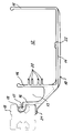
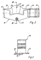
- the individual segment 10 shown in FIGS. 1 to 3 has a step-shaped bottom 11, the upper side of the lower area being aligned with the lower side of the higher area.
- a cheek 14 projects upwards, which is at uneven distances from the two outer legs 15, 16.
- An angular interlocking edge strip 17 is formed on the outer leg 16. The distance between this outer leg and the cheek 14 is significantly smaller than the distance between the cheek 14 and the outer leg 15.
- the single channel 12 with the larger cross-section can be used for laying lines with a mains voltage, while the single channel 13 with the smaller cross-section can be used for low-voltage lines, for example for data transmission.
- four locking webs 20 are formed on the cheek 14, which protrude into the single channel 12 with the larger cross section.
- the area adjoining the floor 11 between the cheek 14 and the leg 16 carrying the hooking edge strip 18 is formed obliquely.
- Figures 2 and 3 show that the bottom 11 is step-shaped, and that the area of the step jump is arcuate.
- An upwardly projecting locking hinge pin 22 is formed on the lower region of the base 11 in the end region.
- a corresponding receptacle 23 is provided on the opposite end region, into which the locking hinge pin 22 of the adjacent individual segment (not shown) engages. This enables a hinge-like connection between the individual segments 10.
- the central transverse axis is shown by the dash-dotted line 24.
- the distance between the locking hinge pin 22 and the central transverse axis 24 is the same as the distance between the receptacle 23 and this axis. The rotational mobility of the individual segments 10 is thereby ensured.
- the locking hinge pin 22 and the receptacle 23 lie in the central longitudinal axis of the individual channel 12, which is delimited by the outer leg 15 and the cheek 14, with the larger cross section.
- the section of the base 11 which carries the latching hinge pin 22 and is displaced downward is designed in the form of a circular arc in the end region, the center lying at the intersection of the central transverse axis with the central longitudinal axis.
- the central region of the base 11 is also arcuate, as shown by the line 25.
- the arch of the floor 11 lying in the middle area is designed in such a way that the mobility is made possible. It results in particular from FIG.
Landscapes
- General Engineering & Computer Science (AREA)
- Engineering & Computer Science (AREA)
- Mechanical Engineering (AREA)
- Mutual Connection Of Rods And Tubes (AREA)
- Connection Of Plates (AREA)
- Details Of Indoor Wiring (AREA)
- Machine Tool Units (AREA)
- Surgical Instruments (AREA)
- Massaging Devices (AREA)
- Measuring Pulse, Heart Rate, Blood Pressure Or Blood Flow (AREA)
- Supports Or Holders For Household Use (AREA)
- Furniture Connections (AREA)
- Snaps, Bayonet Connections, Set Pins, And Snap Rings (AREA)
- Seal Device For Vehicle (AREA)
- Cable Accessories (AREA)
- Milling, Drilling, And Turning Of Wood (AREA)
- Vending Machines For Individual Products (AREA)
- Mechanical Coupling Of Light Guides (AREA)
- Body Structure For Vehicles (AREA)
- Legs For Furniture In General (AREA)
- Hooks, Suction Cups, And Attachment By Adhesive Means (AREA)
- Clamps And Clips (AREA)
Applications Claiming Priority (2)
| Application Number | Priority Date | Filing Date | Title |
|---|---|---|---|
| DE9418403 | 1994-10-20 | ||
| DE9418403U | 1994-10-20 |
Publications (3)
| Publication Number | Publication Date |
|---|---|
| EP0707811A2 true EP0707811A2 (fr) | 1996-04-24 |
| EP0707811A3 EP0707811A3 (fr) | 2000-10-18 |
| EP0707811B1 EP0707811B1 (fr) | 2006-07-19 |
Family
ID=6916234
Family Applications (4)
| Application Number | Title | Priority Date | Filing Date |
|---|---|---|---|
| EP95116554A Expired - Lifetime EP0708255B1 (fr) | 1994-10-20 | 1995-10-20 | Unité modulaire avec verrouillage par encliquetage démontable |
| EP95116550A Expired - Lifetime EP0707811B1 (fr) | 1994-10-20 | 1995-10-20 | Canalisation pour câbles électriques |
| EP95116551A Expired - Lifetime EP0707809B1 (fr) | 1994-10-20 | 1995-10-20 | Table de travail |
| EP95116553A Expired - Lifetime EP0707808B1 (fr) | 1994-10-20 | 1995-10-20 | Adaptateur |
Family Applications Before (1)
| Application Number | Title | Priority Date | Filing Date |
|---|---|---|---|
| EP95116554A Expired - Lifetime EP0708255B1 (fr) | 1994-10-20 | 1995-10-20 | Unité modulaire avec verrouillage par encliquetage démontable |
Family Applications After (2)
| Application Number | Title | Priority Date | Filing Date |
|---|---|---|---|
| EP95116551A Expired - Lifetime EP0707809B1 (fr) | 1994-10-20 | 1995-10-20 | Table de travail |
| EP95116553A Expired - Lifetime EP0707808B1 (fr) | 1994-10-20 | 1995-10-20 | Adaptateur |
Country Status (5)
| Country | Link |
|---|---|
| EP (4) | EP0708255B1 (fr) |
| AT (4) | ATE333227T1 (fr) |
| DE (5) | DE59510377D1 (fr) |
| DK (1) | DK0707808T3 (fr) |
| ES (1) | ES2181739T3 (fr) |
Families Citing this family (2)
| Publication number | Priority date | Publication date | Assignee | Title |
|---|---|---|---|---|
| DE102008045080A1 (de) * | 2008-08-29 | 2010-03-18 | Roto Frank Ag | Nutenstein |
| DE112013002839A5 (de) | 2012-06-06 | 2015-03-26 | Günter Witteborg | Verbindungssystem sowie Verbindungselemente für den Ladenbau und Möbelstücke |
Family Cites Families (18)
| Publication number | Priority date | Publication date | Assignee | Title |
|---|---|---|---|---|
| GB596717A (en) * | 1944-08-09 | 1948-01-09 | Joachim Mugnier | Improvements in multiple table desks |
| US3580652A (en) * | 1968-12-19 | 1971-05-25 | Max Bodenhoff As | Typewriter table |
| DE2220675A1 (de) * | 1972-04-27 | 1973-11-15 | Gerold Schatz | Beschlag zur loesbaren verbindung zweier teile, insbesondere moebelteile |
| CH588233A5 (fr) * | 1974-12-09 | 1977-05-31 | Syma Intercontinental Sa | |
| FR2358127A1 (fr) * | 1976-07-12 | 1978-02-10 | Marcadet Mobilier Ateliers | Structure porteuse pour assemblage d'elements modulaires constitutifs de bureaux, de configurations diverses |
| GB2068320B (en) * | 1980-01-30 | 1983-11-30 | Vickers Ltd | Marine tether anchoring device |
| US4410157A (en) * | 1980-02-28 | 1983-10-18 | Monti Carmel S | Photography stand system |
| DE3379750D1 (en) * | 1982-06-07 | 1989-06-01 | Haworth Inc | Adjustable support for crt keyboard |
| DE8421798U1 (de) * | 1984-07-21 | 1984-10-18 | Trilux-Lenze Gmbh + Co Kg, 5760 Arnsberg | Halter für Schläuche, Kabel od. dgl. an Tragschienen |
| FR2595124B1 (fr) * | 1986-03-03 | 1988-09-30 | Lopez Michel | Dispositif pour realiser liaison et ancrage anti-rotation |
| GB2188691A (en) * | 1986-04-01 | 1987-10-07 | John William Stamper | Quick release plug |
| US4802700B1 (en) * | 1987-11-09 | 1996-10-01 | Transguard Ind Inc | Locking seal |
| US4869564A (en) * | 1988-08-24 | 1989-09-26 | Nova Office Furniture, Inc. | Modular furniture |
| IT216638Z2 (it) * | 1989-06-01 | 1991-09-17 | Coopsette Scrl | Complesso guidacavo flessibile ad inserimento trasversale dei cavi. |
| DE4014082A1 (de) * | 1990-05-02 | 1991-11-07 | 3K Bueromoebel Gmbh | Kabelkanal fuer winkelelemente von bueromoebel-winkelkombinationen |
| ES2022036A6 (es) * | 1990-06-18 | 1991-11-16 | Mobel Linea S L | Estructura para la formacion de muebles de oficina y similares. |
| US5162614A (en) * | 1991-04-16 | 1992-11-10 | Molex Incorporated | Raceway for housing electrical components |
| DE29517115U1 (de) * | 1994-10-20 | 1995-12-21 | Flötotto Einrichtungssysteme GmbH & Co KG, 33335 Gütersloh | Möbelbeschlag zum Verbinden von Möbelelementen und damit herstellbare Möbelverbindung |
-
1995
- 1995-10-20 DE DE59510377T patent/DE59510377D1/de not_active Expired - Fee Related
- 1995-10-20 EP EP95116554A patent/EP0708255B1/fr not_active Expired - Lifetime
- 1995-10-20 ES ES95116553T patent/ES2181739T3/es not_active Expired - Lifetime
- 1995-10-20 AT AT95116550T patent/ATE333227T1/de not_active IP Right Cessation
- 1995-10-20 DE DE59509837T patent/DE59509837D1/de not_active Expired - Fee Related
- 1995-10-20 DE DE29516592U patent/DE29516592U1/de not_active Expired - Lifetime
- 1995-10-20 EP EP95116550A patent/EP0707811B1/fr not_active Expired - Lifetime
- 1995-10-20 DE DE59511057T patent/DE59511057D1/de not_active Expired - Fee Related
- 1995-10-20 AT AT95116553T patent/ATE224159T1/de not_active IP Right Cessation
- 1995-10-20 EP EP95116551A patent/EP0707809B1/fr not_active Expired - Lifetime
- 1995-10-20 AT AT95116554T patent/ATE286213T1/de not_active IP Right Cessation
- 1995-10-20 DE DE59510983T patent/DE59510983D1/de not_active Expired - Fee Related
- 1995-10-20 EP EP95116553A patent/EP0707808B1/fr not_active Expired - Lifetime
- 1995-10-20 AT AT95116551T patent/ATE208579T1/de not_active IP Right Cessation
- 1995-10-20 DK DK95116553T patent/DK0707808T3/da active
Non-Patent Citations (1)
| Title |
|---|
| None |
Also Published As
| Publication number | Publication date |
|---|---|
| DE29516592U1 (de) | 1996-01-11 |
| EP0707809A3 (fr) | 2000-10-18 |
| EP0708255A3 (fr) | 2000-12-13 |
| ES2181739T3 (es) | 2003-03-01 |
| EP0707809A2 (fr) | 1996-04-24 |
| DE59509837D1 (de) | 2001-12-20 |
| ATE224159T1 (de) | 2002-10-15 |
| EP0707808B1 (fr) | 2002-09-18 |
| EP0708255A2 (fr) | 1996-04-24 |
| DK0707808T3 (da) | 2002-12-23 |
| ATE208579T1 (de) | 2001-11-15 |
| ATE333227T1 (de) | 2006-08-15 |
| DE59510983D1 (de) | 2005-02-03 |
| EP0707808A2 (fr) | 1996-04-24 |
| DE59510377D1 (de) | 2002-10-24 |
| ATE286213T1 (de) | 2005-01-15 |
| EP0708255B1 (fr) | 2004-12-29 |
| EP0707811B1 (fr) | 2006-07-19 |
| DE59511057D1 (de) | 2006-08-31 |
| EP0707811A3 (fr) | 2000-10-18 |
| EP0707809B1 (fr) | 2001-11-14 |
| EP0707808A3 (fr) | 2000-12-13 |
Similar Documents
| Publication | Publication Date | Title |
|---|---|---|
| EP0404284B1 (fr) | Charpente pour une cabine de distribution à éléments profilés coudés plusieurs fois | |
| DE69801988T2 (de) | Rahmen für elektrische verdrahtung | |
| DE3742448A1 (de) | Kabelkanal | |
| EP1994614B1 (fr) | Construction a cadre pour une armoire electrique, armoire electrique et kit pour l'armoire electrique | |
| DE3708357A1 (de) | Leitungsinstallationskanal | |
| EP0471889A2 (fr) | Dispositif de raccord détachable de deux profiles | |
| DE3113679A1 (de) | Installationsgeraetedose zum einbau in installationskanaele | |
| DE1465876A1 (de) | Einrichtung zur Verteilung elektrischer Energie | |
| EP0308958A2 (fr) | Chaîne porteuse pour lignes de transport d'énérgie | |
| EP0248160A2 (fr) | Support pour barres omnibus | |
| EP0212158B1 (fr) | Dispositif palpeur de profil | |
| EP0867996B1 (fr) | Support pour barres d'un jeu de barres omnibus | |
| EP0154813A1 (fr) | Dispositif de fixation pour machine-outil | |
| DE3908330C1 (en) | Device for covering busbars | |
| DE2852829A1 (de) | Schnellmontagesockel aus kunststoff | |
| EP0707811A2 (fr) | Canalisation pour câbles électriques | |
| EP0423474B1 (fr) | Dispositif pour relier deux baguettes profilées de façon à ce qu'elles soient détachables | |
| EP0623530A1 (fr) | Système de convoyeur aérien avec un set de profilés de montage | |
| DE3721413A1 (de) | Klemmengehaeuse fuer mehretagige klemmenbloecke | |
| DE19710002C1 (de) | Verbinder zum Verbinden von Stromsammelschienen eines Sammelschienensystems | |
| DE3206417C2 (de) | Aneinander anreihbare Stromschienenhalter aus Isolierstoff | |
| DE2804419A1 (de) | Installationskanal | |
| DE69509447T2 (de) | Gerätechassis, insbesondere für ein elektrisches Gehäuse | |
| EP1021973A2 (fr) | Profilé ouvert et creux | |
| DE69212395T2 (de) | Elektrische Anschlussleiste |
Legal Events
| Date | Code | Title | Description |
|---|---|---|---|
| PUAI | Public reference made under article 153(3) epc to a published international application that has entered the european phase |
Free format text: ORIGINAL CODE: 0009012 |
|
| AK | Designated contracting states |
Kind code of ref document: A2 Designated state(s): AT BE CH DE DK ES FR GB IT LI NL SE |
|
| PUAL | Search report despatched |
Free format text: ORIGINAL CODE: 0009013 |
|
| AK | Designated contracting states |
Kind code of ref document: A3 Designated state(s): AT BE CH DE DK ES FR GB IT LI NL SE |
|
| 17P | Request for examination filed |
Effective date: 20001115 |
|
| 17Q | First examination report despatched |
Effective date: 20010219 |
|
| APBZ | Receipt of observations in appeal recorded |
Free format text: ORIGINAL CODE: EPIDOSNOBA4E |
|
| APBT | Appeal procedure closed |
Free format text: ORIGINAL CODE: EPIDOSNNOA9E |
|
| GRAP | Despatch of communication of intention to grant a patent |
Free format text: ORIGINAL CODE: EPIDOSNIGR1 |
|
| GRAS | Grant fee paid |
Free format text: ORIGINAL CODE: EPIDOSNIGR3 |
|
| APAF | Appeal reference modified |
Free format text: ORIGINAL CODE: EPIDOSCREFNE |
|
| GRAA | (expected) grant |
Free format text: ORIGINAL CODE: 0009210 |
|
| AK | Designated contracting states |
Kind code of ref document: B1 Designated state(s): AT BE CH DE DK ES FR GB IT LI NL SE |
|
| PG25 | Lapsed in a contracting state [announced via postgrant information from national office to epo] |
Ref country code: IT Free format text: LAPSE BECAUSE OF FAILURE TO SUBMIT A TRANSLATION OF THE DESCRIPTION OR TO PAY THE FEE WITHIN THE PRESCRIBED TIME-LIMIT;WARNING: LAPSES OF ITALIAN PATENTS WITH EFFECTIVE DATE BEFORE 2007 MAY HAVE OCCURRED AT ANY TIME BEFORE 2007. THE CORRECT EFFECTIVE DATE MAY BE DIFFERENT FROM THE ONE RECORDED. Effective date: 20060719 Ref country code: GB Free format text: LAPSE BECAUSE OF FAILURE TO SUBMIT A TRANSLATION OF THE DESCRIPTION OR TO PAY THE FEE WITHIN THE PRESCRIBED TIME-LIMIT Effective date: 20060719 |
|
| REG | Reference to a national code |
Ref country code: GB Ref legal event code: FG4D Free format text: NOT ENGLISH |
|
| REG | Reference to a national code |
Ref country code: CH Ref legal event code: NV Representative=s name: ISLER & PEDRAZZINI AG Ref country code: CH Ref legal event code: EP |
|
| REF | Corresponds to: |
Ref document number: 59511057 Country of ref document: DE Date of ref document: 20060831 Kind code of ref document: P |
|
| PG25 | Lapsed in a contracting state [announced via postgrant information from national office to epo] |
Ref country code: SE Free format text: LAPSE BECAUSE OF FAILURE TO SUBMIT A TRANSLATION OF THE DESCRIPTION OR TO PAY THE FEE WITHIN THE PRESCRIBED TIME-LIMIT Effective date: 20061019 Ref country code: DK Free format text: LAPSE BECAUSE OF FAILURE TO SUBMIT A TRANSLATION OF THE DESCRIPTION OR TO PAY THE FEE WITHIN THE PRESCRIBED TIME-LIMIT Effective date: 20061019 |
|
| PG25 | Lapsed in a contracting state [announced via postgrant information from national office to epo] |
Ref country code: ES Free format text: LAPSE BECAUSE OF FAILURE TO SUBMIT A TRANSLATION OF THE DESCRIPTION OR TO PAY THE FEE WITHIN THE PRESCRIBED TIME-LIMIT Effective date: 20061030 |
|
| PG25 | Lapsed in a contracting state [announced via postgrant information from national office to epo] |
Ref country code: LI Free format text: LAPSE BECAUSE OF NON-PAYMENT OF DUE FEES Effective date: 20061031 Ref country code: CH Free format text: LAPSE BECAUSE OF NON-PAYMENT OF DUE FEES Effective date: 20061031 |
|
| GBV | Gb: ep patent (uk) treated as always having been void in accordance with gb section 77(7)/1977 [no translation filed] |
Effective date: 20060719 |
|
| PG25 | Lapsed in a contracting state [announced via postgrant information from national office to epo] |
Ref country code: NL Free format text: LAPSE BECAUSE OF NON-PAYMENT OF DUE FEES Effective date: 20070501 |
|
| EN | Fr: translation not filed | ||
| PLBE | No opposition filed within time limit |
Free format text: ORIGINAL CODE: 0009261 |
|
| STAA | Information on the status of an ep patent application or granted ep patent |
Free format text: STATUS: NO OPPOSITION FILED WITHIN TIME LIMIT |
|
| REG | Reference to a national code |
Ref country code: CH Ref legal event code: PL |
|
| 26N | No opposition filed |
Effective date: 20070420 |
|
| NLV4 | Nl: lapsed or anulled due to non-payment of the annual fee |
Effective date: 20070501 |
|
| BERE | Be: lapsed |
Owner name: SCHUCO INTERNATIONAL K.G. Effective date: 20061031 |
|
| PG25 | Lapsed in a contracting state [announced via postgrant information from national office to epo] |
Ref country code: AT Free format text: LAPSE BECAUSE OF NON-PAYMENT OF DUE FEES Effective date: 20061020 |
|
| PG25 | Lapsed in a contracting state [announced via postgrant information from national office to epo] |
Ref country code: FR Free format text: LAPSE BECAUSE OF FAILURE TO SUBMIT A TRANSLATION OF THE DESCRIPTION OR TO PAY THE FEE WITHIN THE PRESCRIBED TIME-LIMIT Effective date: 20070511 |
|
| PG25 | Lapsed in a contracting state [announced via postgrant information from national office to epo] |
Ref country code: FR Free format text: LAPSE BECAUSE OF FAILURE TO SUBMIT A TRANSLATION OF THE DESCRIPTION OR TO PAY THE FEE WITHIN THE PRESCRIBED TIME-LIMIT Effective date: 20060719 |
|
| PGFP | Annual fee paid to national office [announced via postgrant information from national office to epo] |
Ref country code: DE Payment date: 20081024 Year of fee payment: 14 |
|
| PG25 | Lapsed in a contracting state [announced via postgrant information from national office to epo] |
Ref country code: BE Free format text: LAPSE BECAUSE OF FAILURE TO SUBMIT A TRANSLATION OF THE DESCRIPTION OR TO PAY THE FEE WITHIN THE PRESCRIBED TIME-LIMIT Effective date: 20061031 |
|
| PG25 | Lapsed in a contracting state [announced via postgrant information from national office to epo] |
Ref country code: DE Free format text: LAPSE BECAUSE OF NON-PAYMENT OF DUE FEES Effective date: 20100501 |