EP0707839A1 - Oberschenkelgelenkprothese des Knies - Google Patents
Oberschenkelgelenkprothese des Knies Download PDFInfo
- Publication number
- EP0707839A1 EP0707839A1 EP95402203A EP95402203A EP0707839A1 EP 0707839 A1 EP0707839 A1 EP 0707839A1 EP 95402203 A EP95402203 A EP 95402203A EP 95402203 A EP95402203 A EP 95402203A EP 0707839 A1 EP0707839 A1 EP 0707839A1
- Authority
- EP
- European Patent Office
- Prior art keywords
- prosthesis
- femoral
- flattened
- towards
- posterior
- Prior art date
- Legal status (The legal status is an assumption and is not a legal conclusion. Google has not performed a legal analysis and makes no representation as to the accuracy of the status listed.)
- Withdrawn
Links
Images

Classifications
-
- A—HUMAN NECESSITIES
- A61—MEDICAL OR VETERINARY SCIENCE; HYGIENE
- A61F—FILTERS IMPLANTABLE INTO BLOOD VESSELS; PROSTHESES; DEVICES PROVIDING PATENCY TO, OR PREVENTING COLLAPSING OF, TUBULAR STRUCTURES OF THE BODY, e.g. STENTS; ORTHOPAEDIC, NURSING OR CONTRACEPTIVE DEVICES; FOMENTATION; TREATMENT OR PROTECTION OF EYES OR EARS; BANDAGES, DRESSINGS OR ABSORBENT PADS; FIRST-AID KITS
- A61F2/00—Filters implantable into blood vessels; Prostheses, i.e. artificial substitutes or replacements for parts of the body; Appliances for connecting them with the body; Devices providing patency to, or preventing collapsing of, tubular structures of the body, e.g. stents
- A61F2/02—Prostheses implantable into the body
- A61F2/30—Joints
- A61F2/38—Joints for elbows or knees
- A61F2/3859—Femoral components
Definitions
- the present application relates to a tri-compartmental knee joint prosthesis, and in particular its first-line femoral component.
- knee joint prostheses are already known. These conventionally include a femoral element and a tibial element, both preferably metallic, which are fixed on the corresponding bones.
- These prostheses also include an element generally made of plastic material such as polyethylene, which recreates the articular surface of the tibia and which is interposed between the femoral and tibial elements.
- the set of the three aforementioned parts constitutes what is called a tri-compartmental prosthesis.
- the PCA prosthesis for its part, has asymmetrical condyles comprising a tibial plateau notched at the posterior part allowing the conservation of the posterior cruciate ligament.
- the patellar button is asymmetrical and comprises, at the level of the bone contact zone, a porous coating allowing its implantation without the use of cement.
- the femoral component has divergent condyles and different radii of curvature.
- the patella has an asymmetrical shape, close to the anatomical shape.
- EP-A-0 600 806 describes a tri-compartment knee prosthesis comprising a femoral implant and a tibial implant, the femoral implant being of the type having a notch delimiting two condylar support pads joined by a trochlea, in which the femoral implant has an anatomical shape resulting from the combination of a number of characteristics.
- the length of the posterior curvature is greater on the condylar pads, so that their thickness at this posterior part, therefore towards the outside of the prosthesis, is greater than that known to date on existing prostheses; this characteristic is presented as improving flexion.
- EP-A-0 567 705 relates to a total postero-stabilized knee prosthesis comprising a femoral element, two condyles, and a postero-stabilization abutment facing forward and partially occupying the intercondylar space.
- prostheses show that the various companies involved in this type of research aim to provide prosthetic parts that are as close as possible to human anatomy, in order to better respect the ligament kinematics and thus obtain the best performance.
- the fixation of the femoral part of the prosthesis in the femur is always accompanied by a significant bone resection, and therefore we often arrive at the cancellous bone.
- Fixing such a prosthesis in a cancellous element is, of course, less effective than an installation in hard bone.
- it is desirable that the installation of a prosthesis allows the patients thus fitted to have a knee flexion amplitude as close as possible to the physiological amplitude.
- a one-piece femoral prosthesis for knee articulation comprising a support body provided with an anterior trochlear part, a median part and two posterior condylar parts, said support body.
- a curved strip comprising a central recess thus constituting two strips similar to condyles, each of the two strips comprising an anchoring stud near the middle part of said support body, characterized in that the posterior condylar parts have an inward thickness of the prosthesis thereby increasing the flexion angle of a femur comprising such a prosthesis before the blocking of the flexion by cam effect on a tibial prosthetic element, said excess thickness corresponding to an extension (A) of the posterior curvature of the condyles from 3 mm to 10 mm towards the inside of the prosthesis.
- A extension
- femoral prosthesis is meant that it is a first-line prosthesis, and not a revision prosthesis that can be adjusted using shims of dimensions adapted to the game to be compensated.
- the aforementioned extra thickness corresponds to an extension (A) of the posterior curvature of the condyles from 3 mm to 10 mm towards the inside of the prosthesis.
- the meaning and illustration of this extension (A) will be seen below in the figures.
- the maximum thickness of the condylar part of the prosthesis according to the invention can range from 11.5 to 16.5 mm depending on the size of the femur; for example for a medium femur, this thickness will be approximately 14.5 mm.
- the femoral prosthesis according to the invention has a median portion of an unusually reduced thickness.
- the thickness e of the middle part may for example have from 5 mm to 8 mm, and preferably this thickness "e" does not exceed 6 mm.
- the prosthesis according to the invention is characterized in that the middle part comprises, in the width direction, and towards the inside of said prosthesis four surfaces in contact with the bone, two of these, more external and substantially coplanar, are flattened and form a plane substantially perpendicular to the femoral axis, and the other two, internal and curved, are directed towards the interior of the femur, namely towards the middle part of the intercondylar space, the two external surfaces being located 5 to 10 mm below the upper level of the middle part of the prosthesis.
- Preferred prostheses among the above prostheses are those characterized in that, in addition, the intermediate part between the middle part and the trochlear end also comprises flattened surfaces, similar to the two external flattened surfaces but placed in an oblique position with respect to these.
- prostheses are prostheses characterized in that, in addition, the flattened surfaces defined above form an angle of approximately 45 ° with respect to those defined above and the posterior condylar end also includes flattened surfaces, similar to the two external flattened surfaces but placed in an oblique position with respect thereto.
- the external flattened median surfaces form an angle of approximately 40 °, for example 35 to 50 ° with respect to the flattened analogous parts situated at the level of the intermediate parts between the middle part and on the one hand the trochlear end and on the other hand, the posterior condylar end.
- all the curved surfaces defined above may, in whole or in part, be planar.
- the present application also relates to a tri-compartmental knee prosthesis, characterized in that it comprises a femoral prosthesis as defined above.
- Figure 1 shows a perspective view of a right femoral knee joint prosthesis according to the present invention.
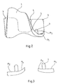
- FIG. 2 represents a straight femoral prosthesis according to the invention seen from the front on the side of the trochlea.
- Figure 3 is a sectional view along BB 'of Figure 1.
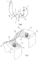
- FIG. 4 represents a straight femoral prosthesis according to the invention seen in profile.
- Figure 5 is a perspective view of internal surfaces (therefore in contact with the femoral bone) of a prosthesis according to the invention.
- Figure 1 there are conventional elements of a femoral knee joint prosthesis.
- This includes an anterior trochlear part 1, a middle part 2, and two posterior condylar parts 3.
- the support body is in the general form of a curved band, with asymmetrical curvature, of greater radius on the trochlear side.
- This curved strip has a central recess 4 constituting two strips similar to condyles.
- Each of these bands has an anchoring stud 7 near the middle part of the support body.
- the condylar bands (5a, 5b) according to the invention have an additional thickness (6a, 6b) towards the interior of the prosthesis on the posterior condylar part.
- This extra thickness represented by A in the figure has the effect of increasing the flexion angle of a femur comprising such a prosthesis before the blocking of the flexion occurs by cam effect on the tibial part of a prosthetic element.
- the prostheses according to the invention therefore have the surface of their condyles extended compared to conventional prostheses. This extension A can range from 3 mm to 10 mm depending on the size. It cooperates with a corresponding bone cut more important at this level than in the prior art.
- the posterior cut is of the order of 8 mm.
- this cut is larger but does not significantly weaken the bone support at this level. Bone savings are less important here than gain in flexion, which provides significant comfort when walking.
- the prosthesis according to the invention meets a second objective: it makes it possible to have an anchoring which is situated in the solid part of the bone, avoiding at most a fixation in cancellous bone.
- the prosthesis according to the invention is characterized in that its median part 2 comprises in the direction of the width and inside said prosthesis, that is to say on the side opposite to the sliding surfaces, two surfaces flattened: P1 and P2, and two rounded surfaces: P3 and P4, P4 not being visible in this figure 1 but corresponding to the part P3.
- the first two, P1 and P2, external to the prosthesis are substantially coplanar and thus form a plane substantially perpendicular to the femoral axis.
- These two external flattened surfaces have the distinction of being located (2 mm to 10 mm) below the upper level 8 of the middle part of the prosthesis.
- the two rounded surfaces, P3 and P4, internal with respect to the prosthesis are therefore directed towards the inside of the femur, namely towards the middle part 4 of the inter-condylar space.
- This zone is a continuous zone, namely that the left and right (or internal and external) surfaces of the prosthesis are not separated at this level by the central recess 4.
- the thickness e is generally less than 8 mm, and in general equal to approximately 6 mm.
- the bone resection is done above the point designated by S in the figure.
- the entire anchoring pad 7 is incorporated into hard bone, and not into cancellous bone. Indeed, as can be seen in the figure, the extreme part of the stud is hardly beyond the plane delimited by the point designated by S.
- FIG. 4 represents a prosthesis according to the invention seen in profile, from the inside.
- FIG. 5 is a computerized perspective view of the internal surfaces of the prosthesis according to the invention (or of the corresponding femoral resection). Curved surfaces are indicated by hatching.
- the force applied to the femur is transmitted vertically.
- the surfaces transmitting the force are the distal surface and the anterior chamfer.
- the configuration at the distal level of the present invention makes it possible to conserve the maximum of hard bone.
- This hard bone provides a very resistant support surface for the femoral prosthesis and thus prevents the prosthesis from sinking into the cancellous bone.
- the transmitted force is less important. This time the femur is no longer subjected to a compressive force but to a shearing force.
- the force transmitting surface is the surface of the posterior cut of the condyles.
- the density of the bone of the posterior condyle section being substantially constant between the conventional section and the section required by the prosthesis according to the invention, there is no embrittlement of the bone support.
Landscapes
- Health & Medical Sciences (AREA)
- Orthopedic Medicine & Surgery (AREA)
- Physical Education & Sports Medicine (AREA)
- Cardiology (AREA)
- Oral & Maxillofacial Surgery (AREA)
- Transplantation (AREA)
- Engineering & Computer Science (AREA)
- Biomedical Technology (AREA)
- Heart & Thoracic Surgery (AREA)
- Vascular Medicine (AREA)
- Life Sciences & Earth Sciences (AREA)
- Animal Behavior & Ethology (AREA)
- General Health & Medical Sciences (AREA)
- Public Health (AREA)
- Veterinary Medicine (AREA)
- Prostheses (AREA)
Applications Claiming Priority (2)
| Application Number | Priority Date | Filing Date | Title |
|---|---|---|---|
| FR9412347A FR2725618B1 (fr) | 1994-10-17 | 1994-10-17 | Prothese femorale d'articulation du genou |
| FR9412347 | 1994-10-17 |
Publications (1)
| Publication Number | Publication Date |
|---|---|
| EP0707839A1 true EP0707839A1 (de) | 1996-04-24 |
Family
ID=9467912
Family Applications (1)
| Application Number | Title | Priority Date | Filing Date |
|---|---|---|---|
| EP95402203A Withdrawn EP0707839A1 (de) | 1994-10-17 | 1995-10-02 | Oberschenkelgelenkprothese des Knies |
Country Status (2)
| Country | Link |
|---|---|
| EP (1) | EP0707839A1 (de) |
| FR (1) | FR2725618B1 (de) |
Cited By (4)
| Publication number | Priority date | Publication date | Assignee | Title |
|---|---|---|---|---|
| EP1033117A3 (de) * | 1999-03-02 | 2003-01-02 | PLUS Endoprothetik AG | Femurschlitten |
| FR2844704A1 (fr) * | 2002-09-24 | 2004-03-26 | Biomet Merck France | Prothese de genou a plateau mobile |
| US20150182343A1 (en) * | 2013-12-30 | 2015-07-02 | Mako Surgical Corp. | Femoral component for bone conservation |
| ITUA20163373A1 (it) * | 2016-05-12 | 2017-11-12 | Adler Ortho S R L | Componente femorale per protesi di ginocchio e relativa protesi di ginocchio. |
Citations (8)
| Publication number | Priority date | Publication date | Assignee | Title |
|---|---|---|---|---|
| FR2290883A1 (fr) | 1974-11-18 | 1976-06-11 | Nat Res Dev | Endoprothese d'articulation du genou |
| US4586933A (en) | 1983-09-30 | 1986-05-06 | Hiromu Shoji | Dual articulating total knee prosthesis |
| EP0183760A1 (de) | 1984-05-31 | 1986-06-11 | Amersham Int Plc | Nmr-kontrastmittel. |
| EP0378928A1 (de) * | 1988-12-27 | 1990-07-25 | JOHNSON & JOHNSON ORTHOPAEDICS INC. | Revisionsknieprothese |
| WO1990014806A1 (en) * | 1989-06-02 | 1990-12-13 | Chas F Thackray Limited | Improvements in and relating to knee prostheses |
| US5226915A (en) * | 1992-04-03 | 1993-07-13 | Bertin Kim C | Femoral prosthesis component system for knee replacement surgery |
| EP0567705A1 (de) | 1992-04-30 | 1993-11-03 | Merck Biomaterial France S.A. | Totale von hinten stabilisierte Knieprothese |
| EP0600806A1 (de) | 1992-12-01 | 1994-06-08 | Medinov Sa | Aus drei Teilabschnitten gebildete Knieprothese |
-
1994
- 1994-10-17 FR FR9412347A patent/FR2725618B1/fr not_active Expired - Fee Related
-
1995
- 1995-10-02 EP EP95402203A patent/EP0707839A1/de not_active Withdrawn
Patent Citations (8)
| Publication number | Priority date | Publication date | Assignee | Title |
|---|---|---|---|---|
| FR2290883A1 (fr) | 1974-11-18 | 1976-06-11 | Nat Res Dev | Endoprothese d'articulation du genou |
| US4586933A (en) | 1983-09-30 | 1986-05-06 | Hiromu Shoji | Dual articulating total knee prosthesis |
| EP0183760A1 (de) | 1984-05-31 | 1986-06-11 | Amersham Int Plc | Nmr-kontrastmittel. |
| EP0378928A1 (de) * | 1988-12-27 | 1990-07-25 | JOHNSON & JOHNSON ORTHOPAEDICS INC. | Revisionsknieprothese |
| WO1990014806A1 (en) * | 1989-06-02 | 1990-12-13 | Chas F Thackray Limited | Improvements in and relating to knee prostheses |
| US5226915A (en) * | 1992-04-03 | 1993-07-13 | Bertin Kim C | Femoral prosthesis component system for knee replacement surgery |
| EP0567705A1 (de) | 1992-04-30 | 1993-11-03 | Merck Biomaterial France S.A. | Totale von hinten stabilisierte Knieprothese |
| EP0600806A1 (de) | 1992-12-01 | 1994-06-08 | Medinov Sa | Aus drei Teilabschnitten gebildete Knieprothese |
Cited By (13)
| Publication number | Priority date | Publication date | Assignee | Title |
|---|---|---|---|---|
| US10285817B2 (en) | 1999-03-02 | 2019-05-14 | Smith & Nephew Orthopaedics Ag | Femoral slideway and method |
| US7306609B2 (en) | 1999-03-02 | 2007-12-11 | Plus Orthopedics Ag | Femoral slideway |
| EP1033117A3 (de) * | 1999-03-02 | 2003-01-02 | PLUS Endoprothetik AG | Femurschlitten |
| US9265507B2 (en) | 1999-03-02 | 2016-02-23 | Smith & Nephew Orthopaedics Ag | Femoral slideway |
| FR2844704A1 (fr) * | 2002-09-24 | 2004-03-26 | Biomet Merck France | Prothese de genou a plateau mobile |
| EP3508175A1 (de) * | 2013-12-30 | 2019-07-10 | Mako Surgical Corporation | Femurteil für knochenkonservierung |
| US10219908B2 (en) * | 2013-12-30 | 2019-03-05 | Mako Surgical Corp. | Femoral component for bone conservation |
| US20150182343A1 (en) * | 2013-12-30 | 2015-07-02 | Mako Surgical Corp. | Femoral component for bone conservation |
| AU2019203784B2 (en) * | 2013-12-30 | 2020-07-23 | Mako Surgical Corp. | Femoral component for bone conservation |
| US11793649B2 (en) | 2013-12-30 | 2023-10-24 | Mako Surgical Corp. | Femoral component for bone conservation |
| US12310856B2 (en) | 2013-12-30 | 2025-05-27 | Mako Surgical Corp. | Femoral component for bone conservation |
| WO2017194614A1 (en) * | 2016-05-12 | 2017-11-16 | Adler Ortho S.P.A. | Femoral component for knee prosthesis and related knee prosthesis |
| ITUA20163373A1 (it) * | 2016-05-12 | 2017-11-12 | Adler Ortho S R L | Componente femorale per protesi di ginocchio e relativa protesi di ginocchio. |
Also Published As
| Publication number | Publication date |
|---|---|
| FR2725618B1 (fr) | 1997-04-04 |
| FR2725618A1 (fr) | 1996-04-19 |
Similar Documents
| Publication | Publication Date | Title |
|---|---|---|
| EP2303195B1 (de) | Kniegelenkstotalprothese | |
| EP1474079B1 (de) | Kniegelenkstotalprothese | |
| FR3132204A1 (fr) | Prothese de cheville amelioree | |
| EP1354571B1 (de) | Ganzknieprothese | |
| EP1528902B1 (de) | Knieprothese | |
| EP0758218A1 (de) | Knieprothese mit beweglichem meniskus | |
| CH687584A5 (fr) | Prothèse de genou | |
| CH618873A5 (de) | ||
| CH630520A5 (fr) | Prothese d'articulation du genou. | |
| WO1998025550A1 (fr) | Prothese totale d'articulation du genou | |
| FR2812541A1 (fr) | Prothese unicompartimentale du genou | |
| EP1862150A1 (de) | Vollprothese des Kniegelenks | |
| EP0567705A1 (de) | Totale von hinten stabilisierte Knieprothese | |
| FR2780636A1 (fr) | Prothese de genou modulable | |
| FR2852819A1 (fr) | Prothese totale postero-stabilisee du genou | |
| FR2961686A1 (fr) | Dispositif orthopedique destine a equiper l'articulation d'un genou. | |
| WO2002009624A1 (fr) | Prothese bicompartimentale du genou | |
| FR2805456A1 (fr) | Prothese totale de genou, du type dit "postero-stabilisee" | |
| WO1996000538A1 (fr) | Articulation prothetique du genou, notamment prothese unicompartimentale du genou, ou prothese de la rotule | |
| EP0707839A1 (de) | Oberschenkelgelenkprothese des Knies | |
| FR2809302A1 (fr) | Implants orthopediques et plus particulierement des protheses du genou | |
| EP0645126A2 (de) | Bikondyläre, von hinten stabilisierte Kniegelenkprothese | |
| FR2758715A1 (fr) | Prothese de condyle femoral | |
| FR2684291A1 (fr) | Prothese de cheville. | |
| FR2566657A1 (fr) | Prothese du genou a glissement |
Legal Events
| Date | Code | Title | Description |
|---|---|---|---|
| PUAI | Public reference made under article 153(3) epc to a published international application that has entered the european phase |
Free format text: ORIGINAL CODE: 0009012 |
|
| AK | Designated contracting states |
Kind code of ref document: A1 Designated state(s): BE CH DE ES FR GB IT LI NL |
|
| 17P | Request for examination filed |
Effective date: 19960923 |
|
| 17Q | First examination report despatched |
Effective date: 19991215 |
|
| STAA | Information on the status of an ep patent application or granted ep patent |
Free format text: STATUS: THE APPLICATION IS DEEMED TO BE WITHDRAWN |
|
| 18D | Application deemed to be withdrawn |
Effective date: 20000426 |