EP0707879B1 - Filtration apparatus - Google Patents
Filtration apparatus Download PDFInfo
- Publication number
- EP0707879B1 EP0707879B1 EP19950307068 EP95307068A EP0707879B1 EP 0707879 B1 EP0707879 B1 EP 0707879B1 EP 19950307068 EP19950307068 EP 19950307068 EP 95307068 A EP95307068 A EP 95307068A EP 0707879 B1 EP0707879 B1 EP 0707879B1
- Authority
- EP
- European Patent Office
- Prior art keywords
- collar
- tube
- support plate
- filtration apparatus
- annular
- Prior art date
- Legal status (The legal status is an assumption and is not a legal conclusion. Google has not performed a legal analysis and makes no representation as to the accuracy of the status listed.)
- Expired - Lifetime
Links
- 238000001914 filtration Methods 0.000 title claims description 16
- 239000000919 ceramic Substances 0.000 claims description 6
- 239000000463 material Substances 0.000 claims description 3
- 239000002184 metal Substances 0.000 claims description 3
- 229910052751 metal Inorganic materials 0.000 claims description 3
- 239000004033 plastic Substances 0.000 claims description 3
- 229920003023 plastic Polymers 0.000 claims description 3
- 238000007789 sealing Methods 0.000 description 3
- 229910010293 ceramic material Inorganic materials 0.000 description 2
- 230000002093 peripheral effect Effects 0.000 description 2
- 239000004411 aluminium Substances 0.000 description 1
- 229910052782 aluminium Inorganic materials 0.000 description 1
- XAGFODPZIPBFFR-UHFFFAOYSA-N aluminium Chemical compound [Al] XAGFODPZIPBFFR-UHFFFAOYSA-N 0.000 description 1
- 238000005266 casting Methods 0.000 description 1
- 239000002131 composite material Substances 0.000 description 1
- 230000000694 effects Effects 0.000 description 1
- 239000000835 fiber Substances 0.000 description 1
- 238000000034 method Methods 0.000 description 1
- 238000000465 moulding Methods 0.000 description 1
- 125000006850 spacer group Chemical group 0.000 description 1
Images


Classifications
-
- B—PERFORMING OPERATIONS; TRANSPORTING
- B01—PHYSICAL OR CHEMICAL PROCESSES OR APPARATUS IN GENERAL
- B01D—SEPARATION
- B01D46/00—Filters or filtering processes specially modified for separating dispersed particles from gases or vapours
- B01D46/24—Particle separators, e.g. dust precipitators, using rigid hollow filter bodies
- B01D46/2403—Particle separators, e.g. dust precipitators, using rigid hollow filter bodies characterised by the physical shape or structure of the filtering element
- B01D46/2407—Filter candles
-
- B—PERFORMING OPERATIONS; TRANSPORTING
- B01—PHYSICAL OR CHEMICAL PROCESSES OR APPARATUS IN GENERAL
- B01D—SEPARATION
- B01D29/00—Filters with filtering elements stationary during filtration, e.g. pressure or suction filters, not covered by groups B01D24/00 - B01D27/00; Filtering elements therefor
- B01D29/11—Filters with filtering elements stationary during filtration, e.g. pressure or suction filters, not covered by groups B01D24/00 - B01D27/00; Filtering elements therefor with bag, cage, hose, tube, sleeve or like filtering elements
- B01D29/31—Self-supporting filtering elements
- B01D29/33—Self-supporting filtering elements arranged for inward flow filtration
-
- B—PERFORMING OPERATIONS; TRANSPORTING
- B01—PHYSICAL OR CHEMICAL PROCESSES OR APPARATUS IN GENERAL
- B01D—SEPARATION
- B01D46/00—Filters or filtering processes specially modified for separating dispersed particles from gases or vapours
- B01D46/0002—Casings; Housings; Frame constructions
- B01D46/0005—Mounting of filtering elements within casings, housings or frames
-
- B—PERFORMING OPERATIONS; TRANSPORTING
- B01—PHYSICAL OR CHEMICAL PROCESSES OR APPARATUS IN GENERAL
- B01D—SEPARATION
- B01D2271/00—Sealings for filters specially adapted for separating dispersed particles from gases or vapours
- B01D2271/02—Gaskets, sealings
- B01D2271/022—Axial sealings
Definitions
- This invention relates to filtration apparatus and, more particularly, to a means to hold rigid filter tubes in their desired use position.
- Filtration apparatus in which substantially rigid filter tubes e.g. of ceramic material, are usually suspended vertically from a support plate.
- the tubes usually have an annular flange or collar at one end and they are each placed through a hole in the support plate so as to be suspended by their flanges.
- a top plate may be placed over the exposed flanges and the top plate and support plate bolted together at suitable intervals with spacers between the plates whereby the collar of each tube is trapped between the two plates.
- a filtration apparatus of this type may contain a large number of filter tubes, for example from 36 to over 1000.
- Such an apparatus has a number of disadvantages. For example, if one filter tube fails in service, it is necessary to unbolt the entire top plate in order to remove and replace the faulty tube. Moreover, the means by which the tubes are held in place may be inadequate and may in certain circumstances lead to possible fracture of the tubes.
- the invention provides a filtration apparatus comprising a support plate having a plurality of apertures each to receive a filter tube, a plurality of annular collars, each collar being divided by a step into two portions, a first portion of size to pass through an aperture in the plate and a second portion of a size not to pass through an aperture in the plate, each collar thereby being positionable to sit in an aperture in the plate with the exterior of its step contacting the plate around the aperture, each collar having a central through passageway to receive a filter tube with an annular flange adjacent one end, whereby each tube may be positioned to extend through the support plate with its flange in engagement with or adjacent the interior of the step of its respective collar, means to attach each collar to the support plate and means to hold each tube securely in its respective collar.
- the invention also provides in another aspect an annular collar suitable for use in the aforesaid filtration apparatus, the collar being divided by a step into two portions, a first portion of smaller external and internal dimensions than a second portion, the collar having means for attachment to a support plate around an aperture in the support plate through which its first portion can be fitted, and means attachable to the second portion to hold securely in the collar the flange of a flanged filter tube extending through the collar.
- the invention is particularly applicable to use with substantially rigid ceramic filter tubes but is not limited to such use. Thus it may be used with any suitable filter tubes e.g. of porous metal or plastics material. Where a ceramic tube is used it is preferably a composite ceramic fibre product.
- the stepped collar may be formed of ceramic material, metal, e.g. aluminium, or plastics material.
- the invention is particularly useful for filtration apparatus in which the filter tubes are suspended vertically from a support plate and are clamped at their upper ends, it is not limited to such use.
- the tubes may be arranged to extend horizontally and they may, if desired, be supported at both ends.
- the means to attach the collar to the support plate may be, for example, a series of integrally-formed lugs, e.g. four equi-spaced lugs, on the exterior of the collar.
- the lugs may be formed on the second portion of the collar adjacent its step and may be apertured whereby they can be attached to the support plate by suitable bolts.
- the means to hold the filter tube securely in position in the collar may be, for example, an apertured cover plate to sit on top of the tube and a spring circlip to be fitted under a lip at the edge of the second portion of the collar to compress the cover plate and tube against the step of the collar.
- Suitable sealing washers may be incorporated as required between the individual items of the assembled apparatus. Venturi devices may also be positioned in the filter tubes as is conventional practice.
- the collar and the filter tube may be of conventional circular cross-section but, in another preferred embodiment of the invention, they are of non-circular cross-section.
- their sections may be of matching corrugated outline, e.g. in the form of a toothed wheel, or of oval, rectangular or other section.
- the invention provides a filtration apparatus of improved durability and operational flexibility.
- Filter tubes are more securely held in their support plate and, for example, a rigid ceramic filter tube is less likely to fracture. If a single tube fails in use, it can readily be replaced by releasing its securing means including those securing its collar to the support plate, removing the failed tube from the assembly and inserting a new tube.
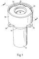
- a ceramic filter tube 10 has an elongated tubular filter body portion 11 and a peripheral flange 12 at one end.
- a stepped collar 13 of the invention has a first portion 14 separated by a step 15 from a second portion 16.
- Body portion 11 of tube 10 is fitted to extend through collar 13 until its flange 12 meets a sealing gasket 17 placed on the interior surface of step 15 in the collar.
- a tapered venturi tube 18 with a flange 19 is fitted inside the flanged end of filter tube 10 so that flange 19 of the venturi tube rests on flange 12 of the filter tube.
- a sealing gasket 23 is positioned between plate 20 and flange 19.
- the second portion 16 of collar 13 has four integrally formed equi-spaced lugs 26 (two only shown) adjacent its step 15. Each lug has an aperture by means of which the collar may be bolted to a filter tube support plate (not shown).
- a multiplicity of filter tubes may be securely fitted into a single support plate by the means of the invention.
Landscapes
- Chemical & Material Sciences (AREA)
- Chemical Kinetics & Catalysis (AREA)
- Physics & Mathematics (AREA)
- Geometry (AREA)
- Filtering Of Dispersed Particles In Gases (AREA)
- Quick-Acting Or Multi-Walled Pipe Joints (AREA)
Applications Claiming Priority (2)
| Application Number | Priority Date | Filing Date | Title |
|---|---|---|---|
| GB9421083 | 1994-10-19 | ||
| GB9421083A GB9421083D0 (en) | 1994-10-19 | 1994-10-19 | Filtration apparatus |
Publications (2)
| Publication Number | Publication Date |
|---|---|
| EP0707879A1 EP0707879A1 (en) | 1996-04-24 |
| EP0707879B1 true EP0707879B1 (en) | 1998-12-02 |
Family
ID=10763093
Family Applications (1)
| Application Number | Title | Priority Date | Filing Date |
|---|---|---|---|
| EP19950307068 Expired - Lifetime EP0707879B1 (en) | 1994-10-19 | 1995-10-05 | Filtration apparatus |
Country Status (5)
| Country | Link |
|---|---|
| EP (1) | EP0707879B1 (da) |
| DE (1) | DE69506362T2 (da) |
| DK (1) | DK0707879T3 (da) |
| ES (1) | ES2127476T3 (da) |
| GB (1) | GB9421083D0 (da) |
Families Citing this family (1)
| Publication number | Priority date | Publication date | Assignee | Title |
|---|---|---|---|---|
| US20230398473A1 (en) * | 2022-06-14 | 2023-12-14 | Clean Air-Engineering - Maritime, Inc. | Filter support system |
Family Cites Families (3)
| Publication number | Priority date | Publication date | Assignee | Title |
|---|---|---|---|---|
| DE9014198U1 (de) * | 1990-10-12 | 1991-03-07 | Thomas Josef Heimbach GmbH & Co, 5160 Düren | Filter, insbesondere Heißgasfilter |
| US5143530A (en) * | 1990-10-22 | 1992-09-01 | Westinghouse Electric Corp. | Filtering apparatus |
| DE9017238U1 (de) * | 1990-12-21 | 1991-02-28 | Thomas Josef Heimbach GmbH & Co, 5160 Düren | Filter |
-
1994
- 1994-10-19 GB GB9421083A patent/GB9421083D0/en active Pending
-
1995
- 1995-10-05 DE DE1995606362 patent/DE69506362T2/de not_active Expired - Fee Related
- 1995-10-05 EP EP19950307068 patent/EP0707879B1/en not_active Expired - Lifetime
- 1995-10-05 DK DK95307068T patent/DK0707879T3/da active
- 1995-10-05 ES ES95307068T patent/ES2127476T3/es not_active Expired - Lifetime
Also Published As
| Publication number | Publication date |
|---|---|
| DE69506362T2 (de) | 1999-08-26 |
| ES2127476T3 (es) | 1999-04-16 |
| GB9421083D0 (en) | 1994-12-07 |
| DK0707879T3 (da) | 1999-08-16 |
| DE69506362D1 (de) | 1999-01-14 |
| EP0707879A1 (en) | 1996-04-24 |
Similar Documents
| Publication | Publication Date | Title |
|---|---|---|
| EP0771582B1 (en) | Filter assemblies and end caps for filter assemblies | |
| US9370740B2 (en) | Modular stacking filter system | |
| RU2668911C2 (ru) | Варианты конструкции и конфигурации фильтрующих картриджей, способы сборки и использование | |
| US4504288A (en) | Tubular-filter device with compressed-air cleanout | |
| US5863313A (en) | Cylindrical air filter with radially directed seal | |
| US6375698B1 (en) | Long filter assembly with connection device | |
| US5601626A (en) | Support construction of filter element in dust collecting apparatus | |
| US3732669A (en) | Fuel gas separator | |
| AU5335899A (en) | Baghouse, long filter assembly and method of installation | |
| US3083953A (en) | Gas diffusion apparatus | |
| US6358292B1 (en) | Pleated filter element with reusable mounting plate | |
| WO2007109563A2 (en) | Filter assembly and adaptor | |
| US5078763A (en) | Air filter cleaning device | |
| EP0707879B1 (en) | Filtration apparatus | |
| US5037461A (en) | Filtration apparatus | |
| EP1819416B1 (en) | Air filter unit | |
| JPH0314487B2 (da) | ||
| US6706182B2 (en) | Caged pleated filter cartridge assemblies and filtration systems employing the same | |
| US4759845A (en) | Plural filter apparatus with filtration gasket | |
| US3291311A (en) | Underdrains | |
| EP0409261B1 (en) | Water vessel | |
| US7294160B2 (en) | Air cleaner | |
| AU5286290A (en) | Light fitting including filter elements | |
| AU2004277277B2 (en) | Improved screen nozzle | |
| JPH07163810A (ja) | 流体の瀘過装置とこの装置を組立てる装置および組立方法 |
Legal Events
| Date | Code | Title | Description |
|---|---|---|---|
| PUAI | Public reference made under article 153(3) epc to a published international application that has entered the european phase |
Free format text: ORIGINAL CODE: 0009012 |
|
| AK | Designated contracting states |
Kind code of ref document: A1 Designated state(s): BE DE DK ES FR GB IT NL SE |
|
| 17P | Request for examination filed |
Effective date: 19960813 |
|
| GRAG | Despatch of communication of intention to grant |
Free format text: ORIGINAL CODE: EPIDOS AGRA |
|
| 17Q | First examination report despatched |
Effective date: 19971211 |
|
| GRAG | Despatch of communication of intention to grant |
Free format text: ORIGINAL CODE: EPIDOS AGRA |
|
| GRAG | Despatch of communication of intention to grant |
Free format text: ORIGINAL CODE: EPIDOS AGRA |
|
| GRAH | Despatch of communication of intention to grant a patent |
Free format text: ORIGINAL CODE: EPIDOS IGRA |
|
| GRAH | Despatch of communication of intention to grant a patent |
Free format text: ORIGINAL CODE: EPIDOS IGRA |
|
| GRAA | (expected) grant |
Free format text: ORIGINAL CODE: 0009210 |
|
| AK | Designated contracting states |
Kind code of ref document: B1 Designated state(s): BE DE DK ES FR GB IT NL SE |
|
| REF | Corresponds to: |
Ref document number: 69506362 Country of ref document: DE Date of ref document: 19990114 |
|
| ITF | It: translation for a ep patent filed | ||
| ET | Fr: translation filed | ||
| REG | Reference to a national code |
Ref country code: ES Ref legal event code: FG2A Ref document number: 2127476 Country of ref document: ES Kind code of ref document: T3 |
|
| REG | Reference to a national code |
Ref country code: DK Ref legal event code: T3 |
|
| PLBE | No opposition filed within time limit |
Free format text: ORIGINAL CODE: 0009261 |
|
| STAA | Information on the status of an ep patent application or granted ep patent |
Free format text: STATUS: NO OPPOSITION FILED WITHIN TIME LIMIT |
|
| 26N | No opposition filed | ||
| PGFP | Annual fee paid to national office [announced via postgrant information from national office to epo] |
Ref country code: FR Payment date: 20000911 Year of fee payment: 6 |
|
| PGFP | Annual fee paid to national office [announced via postgrant information from national office to epo] |
Ref country code: DK Payment date: 20000912 Year of fee payment: 6 |
|
| PGFP | Annual fee paid to national office [announced via postgrant information from national office to epo] |
Ref country code: SE Payment date: 20000920 Year of fee payment: 6 |
|
| PGFP | Annual fee paid to national office [announced via postgrant information from national office to epo] |
Ref country code: NL Payment date: 20000925 Year of fee payment: 6 Ref country code: DE Payment date: 20000925 Year of fee payment: 6 |
|
| PGFP | Annual fee paid to national office [announced via postgrant information from national office to epo] |
Ref country code: ES Payment date: 20001010 Year of fee payment: 6 |
|
| PGFP | Annual fee paid to national office [announced via postgrant information from national office to epo] |
Ref country code: BE Payment date: 20001016 Year of fee payment: 6 |
|
| REG | Reference to a national code |
Ref country code: GB Ref legal event code: 732E |
|
| PG25 | Lapsed in a contracting state [announced via postgrant information from national office to epo] |
Ref country code: DK Free format text: LAPSE BECAUSE OF NON-PAYMENT OF DUE FEES Effective date: 20011005 |
|
| PG25 | Lapsed in a contracting state [announced via postgrant information from national office to epo] |
Ref country code: SE Free format text: LAPSE BECAUSE OF NON-PAYMENT OF DUE FEES Effective date: 20011006 Ref country code: ES Free format text: LAPSE BECAUSE OF NON-PAYMENT OF DUE FEES Effective date: 20011006 |
|
| REG | Reference to a national code |
Ref country code: GB Ref legal event code: 732E |
|
| PG25 | Lapsed in a contracting state [announced via postgrant information from national office to epo] |
Ref country code: BE Free format text: LAPSE BECAUSE OF NON-PAYMENT OF DUE FEES Effective date: 20011031 |
|
| NLS | Nl: assignments of ep-patents |
Owner name: CEREL LIMITED |
|
| REG | Reference to a national code |
Ref country code: GB Ref legal event code: IF02 |
|
| REG | Reference to a national code |
Ref country code: FR Ref legal event code: TP |
|
| BERE | Be: lapsed |
Owner name: CEREL LTD Effective date: 20011031 |
|
| PG25 | Lapsed in a contracting state [announced via postgrant information from national office to epo] |
Ref country code: NL Free format text: LAPSE BECAUSE OF NON-PAYMENT OF DUE FEES Effective date: 20020501 |
|
| EUG | Se: european patent has lapsed |
Ref document number: 95307068.7 |
|
| REG | Reference to a national code |
Ref country code: DK Ref legal event code: EBP |
|
| PG25 | Lapsed in a contracting state [announced via postgrant information from national office to epo] |
Ref country code: FR Free format text: LAPSE BECAUSE OF NON-PAYMENT OF DUE FEES Effective date: 20020628 |
|
| NLV4 | Nl: lapsed or anulled due to non-payment of the annual fee |
Effective date: 20020501 |
|
| PG25 | Lapsed in a contracting state [announced via postgrant information from national office to epo] |
Ref country code: DE Free format text: LAPSE BECAUSE OF NON-PAYMENT OF DUE FEES Effective date: 20020702 |
|
| REG | Reference to a national code |
Ref country code: FR Ref legal event code: ST |
|
| BECA | Be: change of holder's address |
Free format text: 20020108 *CEREL LTD:SWAN HOUSE BOSWORTH HALL THE PARK, MARKET BOSWORTH WARWICKSHIRE CV13 0LJ |
|
| REG | Reference to a national code |
Ref country code: ES Ref legal event code: FD2A Effective date: 20021113 |
|
| PG25 | Lapsed in a contracting state [announced via postgrant information from national office to epo] |
Ref country code: IT Free format text: LAPSE BECAUSE OF NON-PAYMENT OF DUE FEES;WARNING: LAPSES OF ITALIAN PATENTS WITH EFFECTIVE DATE BEFORE 2007 MAY HAVE OCCURRED AT ANY TIME BEFORE 2007. THE CORRECT EFFECTIVE DATE MAY BE DIFFERENT FROM THE ONE RECORDED. Effective date: 20051005 |
|
| PGFP | Annual fee paid to national office [announced via postgrant information from national office to epo] |
Ref country code: GB Payment date: 20130904 Year of fee payment: 19 |
|
| GBPC | Gb: european patent ceased through non-payment of renewal fee |
Effective date: 20141005 |
|
| PG25 | Lapsed in a contracting state [announced via postgrant information from national office to epo] |
Ref country code: GB Free format text: LAPSE BECAUSE OF NON-PAYMENT OF DUE FEES Effective date: 20141005 |