EP0707896A1 - Dispositif d'application de colle et plaque à buse pour le dispositif - Google Patents
Dispositif d'application de colle et plaque à buse pour le dispositif Download PDFInfo
- Publication number
- EP0707896A1 EP0707896A1 EP95116217A EP95116217A EP0707896A1 EP 0707896 A1 EP0707896 A1 EP 0707896A1 EP 95116217 A EP95116217 A EP 95116217A EP 95116217 A EP95116217 A EP 95116217A EP 0707896 A1 EP0707896 A1 EP 0707896A1
- Authority
- EP
- European Patent Office
- Prior art keywords
- outlet openings
- conveying direction
- rows
- row
- nozzle plate
- Prior art date
- Legal status (The legal status is an assumption and is not a legal conclusion. Google has not performed a legal analysis and makes no representation as to the accuracy of the status listed.)
- Granted
Links
- 239000003292 glue Substances 0.000 title claims abstract description 58
- 239000000758 substrate Substances 0.000 claims description 38
- 238000009826 distribution Methods 0.000 claims description 26
- 235000019504 cigarettes Nutrition 0.000 claims description 23
- 238000004519 manufacturing process Methods 0.000 claims description 11
- 239000000463 material Substances 0.000 claims description 11
- 230000015572 biosynthetic process Effects 0.000 claims description 5
- 239000012530 fluid Substances 0.000 claims description 3
- 239000007788 liquid Substances 0.000 abstract 1
- 239000000123 paper Substances 0.000 description 14
- 238000004026 adhesive bonding Methods 0.000 description 9
- 230000002517 constrictor effect Effects 0.000 description 3
- 229910000831 Steel Inorganic materials 0.000 description 2
- 239000000853 adhesive Substances 0.000 description 2
- 230000001070 adhesive effect Effects 0.000 description 2
- 239000011195 cermet Substances 0.000 description 2
- 230000001427 coherent effect Effects 0.000 description 2
- 239000002184 metal Substances 0.000 description 2
- 239000010959 steel Substances 0.000 description 2
- 241001295925 Gegenes Species 0.000 description 1
- 239000004831 Hot glue Substances 0.000 description 1
- 101700004678 SLIT3 Proteins 0.000 description 1
- 102100027339 Slit homolog 3 protein Human genes 0.000 description 1
- 230000006399 behavior Effects 0.000 description 1
- 239000011111 cardboard Substances 0.000 description 1
- 239000000919 ceramic Substances 0.000 description 1
- 238000006243 chemical reaction Methods 0.000 description 1
- 239000011248 coating agent Substances 0.000 description 1
- 238000000576 coating method Methods 0.000 description 1
- 230000006735 deficit Effects 0.000 description 1
- 238000005553 drilling Methods 0.000 description 1
- 230000000694 effects Effects 0.000 description 1
- 239000007789 gas Substances 0.000 description 1
- 239000004922 lacquer Substances 0.000 description 1
- 239000000314 lubricant Substances 0.000 description 1
- 230000033764 rhythmic process Effects 0.000 description 1
- 238000000926 separation method Methods 0.000 description 1
- 230000000391 smoking effect Effects 0.000 description 1
- 239000004753 textile Substances 0.000 description 1
- 230000007704 transition Effects 0.000 description 1
- 238000009827 uniform distribution Methods 0.000 description 1
Images

Classifications
-
- B—PERFORMING OPERATIONS; TRANSPORTING
- B05—SPRAYING OR ATOMISING IN GENERAL; APPLYING FLUENT MATERIALS TO SURFACES, IN GENERAL
- B05C—APPARATUS FOR APPLYING FLUENT MATERIALS TO SURFACES, IN GENERAL
- B05C5/00—Apparatus in which liquid or other fluent material is projected, poured or allowed to flow on to the surface of the work
- B05C5/02—Apparatus in which liquid or other fluent material is projected, poured or allowed to flow on to the surface of the work the liquid or other fluent material being discharged through an outlet orifice by pressure, e.g. from an outlet device in contact or almost in contact, with the work
- B05C5/027—Coating heads with several outlets, e.g. aligned transversally to the moving direction of a web to be coated
Definitions
- the invention relates to a device of the type corresponding to the preamble of claim 1 and a nozzle plate suitable therefor.
- Such devices are mainly used for applying glue or the like to flat gluing material such as blanks or webs of cardboard, paper, textile, nonwoven and the like according to a predetermined pattern.
- the term "fluid application medium such as glue or the like” does not only include other adhesives such as adhesives or hot-melt adhesives, but also means that the invention extends to any application media which, in terms of consistency and physical behavior, is suitable for application with the device Have properties.
- other fluid media in particular viscous media such as lubricants and lacquers and possibly also gases, are therefore suitable as application media if these are to cause chemical reactions in the area of impact on the substrate, for example.
- the substrate will generally pass the fixed device in a flat path. It In principle, however, the substrate can also be fixed and the application device can be moved. Application systems with a combined movement of application device and substrate are also not excluded.
- slot nozzles are used in many cases, as are known from EP 224 855 A2. Such slot nozzles serve their purpose as long as the relative speed of the substrate is not too high compared to the application device.
- the starting point of the invention was, however, the problem of creating strip-shaped glue tracks with an application quantity of 8 to 10 g / m 2 within the track at speeds of over 2OO up to over 6OO m / min. Such speeds occur in the cigarette industry when it comes to applying the glue traces for the longitudinal seam of the cigarette and for sticking the filter and sticking the filter cover paper around the mouthpiece.
- the lack of precision in the width of the glue track in the case of slot nozzles is due to the fact that, given the small application quantities required and the very high conveying speeds of the substrate, the substrate speed is already noticeably higher than the exit speed of the glue from the nozzle.
- the glue strand is stretched in the longitudinal direction after emerging from the nozzle and, because of the constant volume, cannot otherwise constrict in the width direction. This constriction depends on the current conveying speed of the application medium and on the conveying speed of the substrate and therefore fluctuates depending on the operating conditions.
- An application head is known from a company publication of Dittberner GmbH "Cold glue application device" at which a series of small holes of 0, 7 or 1, O mm are arranged side by side perpendicular to the direction of conveyance.
- Cold glue application device at which a series of small holes of 0, 7 or 1, O mm are arranged side by side perpendicular to the direction of conveyance.
- this embodiment too, there is the constricting effect, but this leads here to the glue threads emerging from the individual bores being separated from one another and being deposited on the substrate as individual threads which have no connection to one another transversely to the conveying direction. There is therefore no desired glue track with glue coating that is uniform over the width of the glue track.
- the invention has for its object to provide an application device for the application media in question, by means of which a strip-shaped track can be generated with a width that can be maintained as precisely as possible and evenly distributed over the width of the track, even at very high relative speeds of the substrate to the application device.
- the constriction effect still occurs at the outermost outlet openings of the track and there leads to a lateral constriction of a few percent of the width of the outlet opening there.
- the width error is negligibly small. The reason for this is the division of the entire order into a large number of very small outlet openings, the constriction inside the overall width being masked by the cohesion of the adjacent edges of the individual strands there.
- the cross-sectional dimension for the outlet openings is about 0.2 to 2.0 mm.
- the “row” is to be understood as the connection line of the center points of exit openings adjacent to one another in the transverse direction.
- the clear distance between the outlet openings of the row located in the conveying direction corresponds substantially to the diameter of the outlet openings of the row downstream in the conveying direction.
- the strands of the application medium emerging from the individual outlet openings therefore just touch each other.
- the diameters of the outlet openings of the two rows are equal to one another and, for example, 0.5 mm (claim 6).
- the outlet openings of one and the same row can have the same diameter, which has advantages for manufacturing reasons (claim 8), or can be different (claim 9), in particular a reduction in the diameter of the terminal outlet openings can be expedient in order to reduce the influence of the constriction at the edge to minimize the order.
- the rows of outlet openings should follow one another closely to promote the formation of a coherent track of the application medium.
- the distance in the conveying direction should at most correspond approximately to the diameter of the outlet openings of one of the rows.
- An overlap according to claim 12 can also be recommended with regard to the arrangement in the longitudinal direction, i.e. the rear outlet openings in the conveying direction should engage a little into the gaps between the adjacent front outlet openings. This also promotes the formation of a coherent track of the application medium, because the strand of the application medium from the respective rear outlet opening can already touch the edges of the strands from the adjacent front outlet openings and merge with them before the speed-related lateral constriction plays an important role.
- the outlet openings are arranged in straight rows perpendicular to the conveying direction of the substrate (claim 13) and the outlet openings have a circular cross section (claim 14).
- the outlet openings can be formed by bores of corresponding diameter, which have been produced with twist drills, by electroerosive means or in a similar manner.
- outlet openings do not necessarily have to have a circular cross section. They also do not have to be completely separate from one another in the boundary surface in which they open.
- outlet openings as grooves alternately adjoin one another from different sides on a plane and in the direction of the plane.
- a type of manufacture of such an outlet opening arrangement which is important in practice is the subject of claim 18.
- the application head is divided, and the parts have the grooves in the adjoining dividing surfaces, which can be milled with a suitable tool, namely with a multiple tool several at the same time. Compared to drilling the outlet openings, this represents a simplification in terms of production.
- the application head on which the boundary surface with the discharge openings is formed, is generally made of steel of an already increased hardness, it has been shown that it is precisely at the outlet openings of small cross-sectional dimensions, through which the glue or the like also contributes to the high desired substrate speeds must be pushed through at high speed, show noticeable signs of wear over time.
- the embodiment according to claim 19 is expedient, in which the outlet area is made of a material with increased wear resistance.
- the wear occurs predominantly only in the exit area, so that only this matters. A Manufacturing the entire application head from the material with increased wear resistance would be too expensive and unnecessary outside the exit area.
- the bar be made of an electrically conductive hard material, i.e. made of a hard metal or an electrically conductive ceramic (cermet).
- the reason for the electrical conductivity is that in such materials the fine outlet openings can no longer be drilled with twist drills because the materials may be harder than the drills. Rather, the outlet openings are introduced with an electroerosive device, which requires the workpiece to be conductive.
- the bar can also be composed of individual pieces, but it is preferred if it extends continuously over the entire width of the application head.
- outlet openings are provided in a nozzle plate which can be attached to an application head and which can be unscrewed from the application head when the application pattern is changed without the application head itself having to be dismantled (claim 23).
- the invention is also implemented in such a nozzle plate, which can be designed according to claim 24.
- the distribution chamber is important in order to ensure a uniform exit of the application medium from all outlet openings emerging from the distribution chamber.
- Claim 25 is directed to the presence of a tear-off edge which ensures the smooth transition of the strands or the trace of the application medium to the substrate.
- the tear-off edge is in itself generally known prior art and can be seen, for example, from the Dittberner GmbH company document and from DE 35 O6 393 A1.
- the embodiment according to claim 27 permits continuous lateral connection of application traces generated by adjacent distribution chambers transverse to the conveying direction.
- the invention is also realized according to claim 28 in the important application example of a cigarette manufacturing machine, in which a device for applying strip-shaped glue traces to the cigarette paper or the filter paper comprises features of one of claims 1 to 23 or a nozzle plate with features of one of claims 24 to 27 .
- FIG. 1 shows the application of a strip-shaped application track 1 of a glue to a substrate 2 from a slot nozzle, which is only represented by a line representing the outlet slot 3.
- the substrate 2 for example a paper web or a paper band, runs past the fixed outlet nozzle 3 at a short distance in the direction of the arrow 4.
- the width of such a glue track 1 can be a few millimeters to a few tens of millimeters.
- the width of the glue track 1 essentially corresponds to the width 5 of the outlet nozzle 3.
- the speed is increased to a few hundred meters per minute, it is above the exit speed of the glue from the exit slot 3.
- the glue strand is thereby stretched in the longitudinal direction before it is completely deposited on the substrate 2 and thereby laces laterally in the 1 apparent from its original width 5 to a smaller width 6, which forms the width of the glue track 1 achievable with the outlet slit 3 at the relevant speed.
- the constriction is exaggerated. It is actually in the range of a few%, usually less than about 10%.
- the constriction can also change, so that the desired glue track of defined width cannot be achieved at high speeds with the known exit slot.
- Width fluctuations in the size arrangement in question are particularly unacceptable for the cigarette industry, where the task is to keep the order width as precise as possible, even at very high speeds of up to 600 m / min.
- an application head is shown, with the help of which the width of the trace of an application medium such as glue can be better maintained even at high speeds.
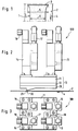
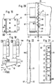
- FIGS. 2 and 3 designated as a whole by 100, which has a cuboidal application head designated as a whole by 10, on the upper side of which, in the operating position, four identical glue valves 13, 14, 15, 16 Connections 17, 18 for the supply of glue and electrical energy for valve control are arranged.
- the application head 10 comprises a plate-shaped carrier 11 with internal openings for the glue, a channel plate 12 arranged underneath with internal channels for distributing the glue and a nozzle plate 20 with a tear-off edge 21 and an arrangement of outlet openings 29, designated as a whole with 30, from which the Glue is dispensed onto the top of the substrate 2 conveyed past or close to it in the direction of arrow 4, specifically controlled by the glue valves 13, 14, 15, 16 that can be electrically controlled due to the high switching frequency.
- FIG. 4 shows the nozzle plate 20 in longitudinal section. It contains blind holes 19 for screws, by means of which the nozzle plate 20 is screwed to the channel plate 12 and the support 11.
- the decisive area is marked by the circle Z.
- the nozzle part 2O has in its rear part an inclined underside 7 which rises slightly against the flat top 8 against the conveying direction 4. Near the area of the arrangement 30 of the outlet openings 29, the underside 7 merges into a boundary surface 23 which extends at least over the area of this arrangement 30 and is flat and parallel to the substrate 2.
- Distribution chambers 24, 25, 26 extend from the upper side 8, ie the supply side of the nozzle plate 20, into the depth of the nozzle plate 20, through which holes 27 28 are approximately perpendicular to the top 8 of the nozzle plate 2O and to the top of the substrate 2, which open out in the boundary surface 23 into the outlet openings 29, which thus forms the common outlet surface given by the metallic surface of the nozzle plate 2O for the outlet openings 29, which in the
- the embodiment is flat, but this should not preclude curved exit surfaces.
- the distributor chambers 24 are elongated grooves milled into the nozzle plate 20 from above, the bottom 27 of which is almost completely covered by the arrangement 30 of the outlet openings 29.
- one distributor chamber 24, 25, 26 results in a glue track of corresponding width on the substrate 2.
- the arrangement 30 of the outlet openings 29 or of the individual distributor chambers 24, 25, 26 depends on the desired gluing pattern.
- the gluing image is symmetrical to the longitudinal median plane M, i.e. the same distribution chambers 24 ', 25', 26 'are provided in mirror image on the opposite side of the longitudinal center plane M. This arrangement enables a gluing image according to FIG. 24, which will be explained in detail there.
- the distributor chambers 24, 25, 26 have flat connecting channels 34, 35, 36 in the upper side of the nozzle plate 20, into which feed channels of the channel plate 12 open.
- the glue entering from the channel plate 12 from above is deflected horizontally in the feed channels 34, 35, 36 and then again vertically deflected into the distribution chambers 24, 25, 26. This multiple deflection is important for the uniform distribution of the glue in the distribution chambers 24, 25, 26.
- the relatively large flow cross section of the distributor chambers 24, 25, 26 also serves this purpose, which considerably exceeds the total cross section of all the bores 28 opening into the respective distributor chamber and forming the outlet openings 29.
- the distributor chambers 24, 25, ... have a common center line N, which extends transversely to the conveying direction 4 of the substrate 2. They are close to the tear-off edge 21.
- FIG. 7 shows a view against the underside of the arrangement 30 of the outlet openings 29 in the region of the nozzle plate 20 denoted by the circle Z in FIG. 4.
- the individual bores 28 forming the outlet openings 29 in the exemplary embodiment shown have a diameter 31 of 0.5 mm.
- the outlet openings 29 are arranged in two rows staggered in the conveying direction 4, namely in a front row 32 located in the conveying direction and in a row 33 following in the conveying direction 4.
- the clear distances 37 between two adjacent outlet openings 29 of the front row 32 correspond to the diameter 31 of the bores 28.
- the clear distance 38 between the outermost positions of the rear boundary of the row 32 and the front boundary of the row 33 also corresponds to the diameter 31.
- the outlet openings 29 of the rear row 33 are exactly at a gap to the adjacent outlet openings 29 of the front row 32.
- the bore diameters are all identical to one another in FIGS. 7 and 9, but this is not mandatory.
- the bores 28 of the rear row 33 could have a larger diameter than those of the front row 32, which would then have to be moved apart accordingly.
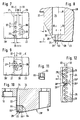
- the outlet openings 29 are generally moved as close as possible to the tear-off edge 21, which is formed on a shoulder 22 (FIGS. 1 and 8) of the underside of the nozzle plate 20 pointing in the conveying direction 4.
- the lower edge of the shoulder 22, which represents the tear-off edge 21, is near to the rear by a bevel 39 'relative to the front boundary of the distributor chamber 24 the outlet openings 29 relocated.
- the bevel 39 'forms an angle ⁇ of 30 ° with a plane perpendicular to the conveying direction 4 (FIG. 8).
- a shallow depression 39 has been worked out in relation to the area on the right, which is to create space for the application medium on the substrate 2 when it is adjacent to the boundary surface 23 Arrangement 30 of the outlet openings 29 is conveyed past.
- FIG. 9 shows a modified exemplary embodiment in which the outlet openings 29 of the front row 32 have moved even closer to the tear-off edge 21.
- the clear distance between two adjacent outlet openings 29 of the front row 32 is 10% smaller than the diameter of the outlet openings 29 of the rear row 33.
- a distance corresponding to the distance 38 between the rear and front boundaries of the rows 32 and 33 no longer exists; rather, the outlet openings 29 of the rear row 33 are pushed forward by about 10% of their diameter between the outlet openings 29 of the front row 32, so that the glue strand emerging from the outlet openings 29 of the rear row immediately makes contact on the sides with those from the adjacent front row Outlet openings 29 exits glue strands at their lateral boundaries.
- Fig. 9 it is indicated by the center lines of the rows 32, 33 that the sequence of bores should continue downwards and upwards, as the width of the glue strip to be produced requires. However, if this glue strip is only to have a small width of approximately 2 mm, the configuration of four bores 28 shown can be sufficient.
- the distributor chamber does not have to consist of an elongated groove, but can be formed by a blind bore which is introduced into the nozzle plate 2O from the top 8 and the outline of which is indicated by the dash-dotted circle K.
- the advantage of the arrangements 30 of outlet openings 29 shown in FIGS. 7 and 9 is particularly noticeable at high speeds of the substrate 2 compared to the application device 100.
- the nozzle plate 20 including the region of the outlet openings 29, was produced in one piece.
- a bar 65 is inserted in the corresponding area 64 of the base body of the nozzle plate 20' in the outlet region, which extends across its width, that is to say perpendicular to the drawing plane according to FIG. 10, which consists of a wear-resistant material, for example a hard material such as hard metal or a cermet.
- the strip 65 is aligned with its front 65 ′ with the shoulder 22 and forms with its underside 65 ′′ the boundary surface 23 in which the outlet openings 29 flow out.
- the strip 65 is fastened to the base body of the nozzle plate 20 'by means of screws which pass through holes 66 in the strip 65, which are offset from the sectional plane of FIG. 10 perpendicular to the plane of the drawing and which are shown in FIG. 11.
- the cross section of the strip 65 is approximately square in the exemplary embodiment shown, but can also be rectangular, for example.
- the pattern of the arrangement and formation of the bores 28 namely continues continuously over the adjacent boundaries 24 ′′ and 25 ′′ of the distributor chambers 24, 25.
- the rows 32, 33 of the bores 28 continue from one distribution chamber 24 into the other distribution chamber 25 without interrupting or changing the division.
- the existence of two distribution chambers 24, 25 cannot be determined at all from the bore pattern. This then also applies to the glue track produced with the arrangement according to FIG. 12, in which the portion produced by the distribution chamber 24 laterally merges with the portion generated by the distribution chamber 25 without the separation point appearing.
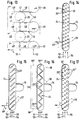
- FIG. 13 shows a detail from the arrangement 30 of the outlet openings 29 corresponding to FIG. 7 in a greatly enlarged manner in order to explain the function of the invention even further.
- the outlet openings 29 are arranged in two rows 32, 33, and the outlet openings of the outlet openings 29 of the row 32 located in the direction of movement 4 of the paper or other substrate are at a gap to the outlet openings 29 of the row 33.
- the traces of application 48 of the row 33 are laced at 46 a little in the transverse direction.
- the diameters and spacings of the outlet openings 29 are coordinated with one another in such a way that the outlet tracks 48 in the row 33 come into contact with the outlet tracks 48 in the row 32 at approximately points 47 and both groups of outlet tracks 48 merge with one another at the lateral edges, so that a uniform order of greater width is achieved.
- the lateral boundaries 48 'of the application tracks 48 disappear shortly after touching the application tracks 48 and are therefore only shown in dashed lines in FIG. 13 for a short piece.
- the outlet openings 29 are arranged in two rows 32, 33, one behind the other in the direction of movement 4. However, this is not mandatory.
- 14 to 17 show exemplary embodiments with more than two rows of outlet openings 29 arranged one behind the other in the direction of movement 4.
- FIG. 14 three rows 52, 53, 54 arranged one behind the other in the direction of movement 4 are each arranged on rectified, ie parallel oblique lines 56 in a distributor chamber 24.
- the principle here is also that in Transverse direction adjacent outlet openings 29 are dimensioned and arranged so that the traces of application in the transverse direction of adjacent outlet openings of the different rows 52, 53, 54 touch and merge at the lateral edges.
- An example is identified in Figure 14 above.
- the application track of the outlet opening 29 of the row 54 touches with its lower longitudinal edge the application track of the outlet opening 29 ′′ of the middle row 53 and with its upper longitudinal edge the application track of the outlet opening 29 ′ of the front row 52.
- the angle 49 which the oblique lines 56 make to the direction of movement 4 is only approximately 25 ° in the exemplary embodiment in FIG. 14, while the corresponding angle 49 'in that 15 is approximately 45 °.
- the outlet openings 29 are provided in four rows 52, 53, 54, 55 in succession in the direction of movement 4 in relatively close succession.
- the oblique lines 57 need to be inclined to a greater extent.
- the oblique lines 58 are arranged in a zigzag, i.e. there are four outlet openings 29 each on oblique lines 58 which form an angle of approximately 90 ° to one another.
- Four rows 52, 53, 54, 55 in succession in the direction of movement are also formed here.
- outlet openings 29 are of the same diameter. This also applies to the outlet openings 29 located in the interior of the distribution chamber 24 in FIG. 16. Only the two terminal, ie outermost outlet openings 29 ''', which are the edges 60' of the order strip 60 produced overall limit are somewhat reduced in diameter in order to further reduce the slight influence of the constriction of the application track (46 in FIG. 13).
- FIG. 17 corresponds to the arrangement of the outlet openings 29 in three rows 52, 53, 54 on parallel inclined lines 59 of FIG. 14.
- the outlet openings 29 1 of the row 53 have a larger diameter than the outlet openings 29 of the row 52 and the outlet openings 292 of the row 54 in turn have a larger diameter than the outlet openings 291 of the row 53.
- the diameters of the outlet openings 292 are approximately twice as large as those of the outlet openings 29.
- the application device 100 of FIG. 2 is shown again in a reduced form, which, however, in this case comprises a nozzle plate 20 ′′, which runs along a plane 63 perpendicular to the substrate (not shown) and to the conveying direction 4 into a left-hand side according to FIG. 18 , ie in the conveying direction 4 angled part and a right part 62 as shown in FIG. 18 is divided.
- the parts 61, 62 are opposed to one another with the flat dividing surfaces 61 'and 62' and connected to one another by screws 67 perpendicular to the plane 63.
- the outlet openings 29 are formed by adjacent grooves 68, which are provided in the mutually opposite dividing surfaces 61 ', 62' of the parts 61, 62.
- flat chambers 69 are formed in the dividing surface 62 ′ and are supplied with glue or the like evenly via channels 70.
- An edge 71 of a few millimeters remains between the chambers 69 and the boundary surface 23 containing the outlet openings 29 Stand width, in which the grooves 68 are milled perpendicular to the boundary surface 23, for example as rectangular grooves with a depth of 0.5 mm and a width of 1 mm.
- the webs 72 that remain between the grooves 68, 68 are as wide as the grooves 68.
- a corresponding groove pattern is milled into the dividing surface 61 'of the part 61, the grooves 68 of which have the same dimensions, but are offset by a groove width in the width direction of the nozzle plate 20' '.
- the webs 72 between the grooves 68 on one side therefore close the grooves 68 on the other side, so that all of the grooves 68 adjoin the plane 63 and adjacent grooves in the plane 63 in the transverse direction of the path abut a common plane 73 perpendicular to the boundary surface 23 or to the substrate and located in the conveying direction.
- FIGS. 18 to 22 there are again rows 32, 33 of outlet openings 29 which lie one behind the other in the conveying direction and which separate glue threads can emerge which immediately touch in the transverse direction after the outlet and form a continuous glue track in the transverse direction.
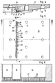
- FIGS. 23, 24 An application example is shown schematically in FIGS. 23, 24.
- This shows a sub-assembly 200 from a cigarette manufacturing machine. It is about attaching the paper mouthpiece to filter cigarettes.
- the cigarettes 40 are produced in another part of the cigarette manufacturing machine as double cigarettes, which are still sitting together with the filter ends. These double cigarettes 40 are conveyed up by a conveying device 41.
- a paper strip 42 runs in from the other side and forms the mouthpiece for the double cigarettes 40 which is glued around the cigarette.
- the paper strip 42 must be as shown in FIG. 24 Patterns are glued, which happens with the aid of the application device 100, which has the nozzle plate 20 of FIG. 5 for this purpose.
- In the middle of the paper strip 42 there is a narrow glue-free strip 45, laterally at a distance from it in each case a series of glue-free rectangles 44 which contain fine perforations which are produced with a laser beam for the supply of secondary air when smoking.
- the gluing strips resulting in the pattern of FIG. 24 are provided in FIG. 24 with the reference numbers of the associated distribution chambers and an underline.
- the leftmost location in Fig. 24 relatively wide Beleimungsst Shape 24 is generated by the distribution chamber 24.
- the interrupted glue strip 24 is generated by the distribution chamber 25, which is switched on and off in rhythm.
- the continuous gluing strip 26 which is produced by the distribution chamber 26 , is adjacent to the center.
- the glue-free narrow strip 45 remains in the middle, where the separating knife later attaches. This strip 45 is caused by the clear distance between the distribution chambers 26 and 24 'in the region of the longitudinal center line M (FIG. 5).
- the web 42 of the tip paper provided with glue in the application device 100 according to the pattern of FIG. 24 runs into an apparatus 43, which is only indicated as a box, in which a section of the band 42 is looped in the middle around a double cigarette 40, glued and in Transverse direction is separated, whereupon the double cigarette 40 now provided with a double mouthpiece in the middle is divided into two single cigarettes 40 'and 40' ', as indicated on the left in FIG. 23.
- the web 42 of the tip paper has a speed of over 200 m / min when it passes the application device 100.
- the gluing must be very thin and even, because any unevenness leads to disruptions in the processing of the cigarettes and, under certain circumstances, also to taste impairments. also narrow tolerances of the gluing width in the transverse direction must be observed, which is achieved by the arrangement 30 of the outlet openings 29.
Landscapes
- Coating Apparatus (AREA)
Priority Applications (1)
| Application Number | Priority Date | Filing Date | Title |
|---|---|---|---|
| US08/546,754 US5769947A (en) | 1994-10-22 | 1995-10-23 | Applicator for adhesive and corresponding nozzle plate |
Applications Claiming Priority (4)
| Application Number | Priority Date | Filing Date | Title |
|---|---|---|---|
| DE4437764 | 1994-10-22 | ||
| DE19944437764 DE4437764A1 (de) | 1994-10-22 | 1994-10-22 | Vorrichtung zum Auftragen von Leim oder dergleichen und dafür geeignete Düsenplatte |
| DE29506334U DE29506334U1 (de) | 1995-04-12 | 1995-04-12 | Vorrichtung zum Auftragen von Leim o.dgl. und dafür geeignete Düsenplatte |
| DE29506334U | 1995-04-12 |
Publications (2)
| Publication Number | Publication Date |
|---|---|
| EP0707896A1 true EP0707896A1 (fr) | 1996-04-24 |
| EP0707896B1 EP0707896B1 (fr) | 2002-09-04 |
Family
ID=25941274
Family Applications (1)
| Application Number | Title | Priority Date | Filing Date |
|---|---|---|---|
| EP95116217A Expired - Lifetime EP0707896B1 (fr) | 1994-10-22 | 1995-10-14 | Dispositif d'application de colle et plaque à buse pour le dispositif |
Country Status (2)
| Country | Link |
|---|---|
| EP (1) | EP0707896B1 (fr) |
| DE (1) | DE59510359D1 (fr) |
Cited By (2)
| Publication number | Priority date | Publication date | Assignee | Title |
|---|---|---|---|---|
| CN113304952A (zh) * | 2021-05-20 | 2021-08-27 | 昆明鼎承科技有限公司 | 一种烟用滤棒包装纸带中线胶涂覆装置及方法 |
| CN119680834A (zh) * | 2024-12-26 | 2025-03-25 | 广东索奇电器科技有限公司 | 用于流水线涂胶机的自动控制方法和系统 |
Citations (5)
| Publication number | Priority date | Publication date | Assignee | Title |
|---|---|---|---|---|
| DE2157710A1 (de) | 1970-11-13 | 1972-07-06 | Nordson Corp | Modulares Gerät zum Abgeben von unter Druck stehender Flüssigkeit |
| DE3223999A1 (de) * | 1981-07-02 | 1983-02-10 | Dynamelt (1981) Ltd., Daventry | Auftragskopf zum aufbringen einer beschichtung auf ein vorbeilaufendes band |
| EP0224855A2 (fr) | 1985-11-26 | 1987-06-10 | Nordson Corporation | Buse à fente |
| DE4013322A1 (de) | 1990-04-26 | 1991-10-31 | Heino Kaiser | Mehrfach-auftragskopf |
| DE9218012U1 (de) * | 1992-04-07 | 1993-08-05 | Eduard Küsters Maschinenfabrik GmbH & Co KG, 47805 Krefeld | Vorrichtung zum Auftragen eines fluiden Behandlungsmediums auf eine laufende Bahn |
-
1995
- 1995-10-14 EP EP95116217A patent/EP0707896B1/fr not_active Expired - Lifetime
- 1995-10-14 DE DE59510359T patent/DE59510359D1/de not_active Expired - Lifetime
Patent Citations (5)
| Publication number | Priority date | Publication date | Assignee | Title |
|---|---|---|---|---|
| DE2157710A1 (de) | 1970-11-13 | 1972-07-06 | Nordson Corp | Modulares Gerät zum Abgeben von unter Druck stehender Flüssigkeit |
| DE3223999A1 (de) * | 1981-07-02 | 1983-02-10 | Dynamelt (1981) Ltd., Daventry | Auftragskopf zum aufbringen einer beschichtung auf ein vorbeilaufendes band |
| EP0224855A2 (fr) | 1985-11-26 | 1987-06-10 | Nordson Corporation | Buse à fente |
| DE4013322A1 (de) | 1990-04-26 | 1991-10-31 | Heino Kaiser | Mehrfach-auftragskopf |
| DE9218012U1 (de) * | 1992-04-07 | 1993-08-05 | Eduard Küsters Maschinenfabrik GmbH & Co KG, 47805 Krefeld | Vorrichtung zum Auftragen eines fluiden Behandlungsmediums auf eine laufende Bahn |
Cited By (2)
| Publication number | Priority date | Publication date | Assignee | Title |
|---|---|---|---|---|
| CN113304952A (zh) * | 2021-05-20 | 2021-08-27 | 昆明鼎承科技有限公司 | 一种烟用滤棒包装纸带中线胶涂覆装置及方法 |
| CN119680834A (zh) * | 2024-12-26 | 2025-03-25 | 广东索奇电器科技有限公司 | 用于流水线涂胶机的自动控制方法和系统 |
Also Published As
| Publication number | Publication date |
|---|---|
| DE59510359D1 (de) | 2002-10-10 |
| EP0707896B1 (fr) | 2002-09-04 |
Similar Documents
| Publication | Publication Date | Title |
|---|---|---|
| EP1147716B1 (fr) | Dispositif d'application de colle sur un matériau d'enveloppement d'un article en forme de tige dans l'industrie du tabac | |
| EP0329829B1 (fr) | Dispositif d'application de colle ou de produit similaire sur une surface | |
| EP0850697B1 (fr) | Dispositif pour l'application de matériaux fluides sur un substrat, en particulier pour l'application intermittente de colles fluides | |
| DE3506393A1 (de) | Leimauftragsvorrichtung | |
| DE19722159A1 (de) | Verfahren und Vorrichtung zum direkten oder indirekten Auftragen eines flüssigen oder pastösen Auftragsmediums auf eine laufende Oberfläche | |
| EP1270810A2 (fr) | Dispositif d'enduction | |
| EP0759328A2 (fr) | Dispositif d'application d'une solution de revêtement | |
| DE2635919A1 (de) | Verfahren und vorrichtung zur formung einer materialbahn | |
| EP3829778A2 (fr) | Jeu de buses pour un pistolet pulvérisateur, système de pistolet pulvérisateur, procédé de réalisation d'un module de buses, procédé de sélection d'un module de buses d'un jeu de buses pour un travail de peinture, système de sélection et produit-programme informatique | |
| EP2646170B1 (fr) | Dispositif permettant l'application de substances visqueuses | |
| EP0224916A1 (fr) | Dispositif d'application intermittente d'adhésifs liquides | |
| DE4437764A1 (de) | Vorrichtung zum Auftragen von Leim oder dergleichen und dafür geeignete Düsenplatte | |
| EP0707896B1 (fr) | Dispositif d'application de colle et plaque à buse pour le dispositif | |
| DE29506334U1 (de) | Vorrichtung zum Auftragen von Leim o.dgl. und dafür geeignete Düsenplatte | |
| EP1749586A1 (fr) | Procédé et dispositif de régulation de la largeur et/ou de la densité d'une masse liquide | |
| EP0570733B1 (fr) | Dispositif d'enduction pour déposer une couleur d'enduction sur une bande de papier | |
| DE10019930A1 (de) | Einrichtung zum Auftragen von Leim auf ein Hüllmaterial eines stabförmigen Artikels der tabakverarbeitenden Industrie | |
| DE4435528A1 (de) | Falztrichter für eine Druckmaschine | |
| DE3517779A1 (de) | Verfahren und vorrichtung zur erzeugung von gemusterten bzw. marmorierten schichten | |
| DE102011118053A1 (de) | Vorhang-Auftragswerk | |
| DE1190368B (de) | Vorrichtung zum elektrostatischen Fluessigkeitsauftragen auf im wesentlichen ebene Werkstueckflaechen | |
| EP0821102B1 (fr) | Dispositif pour l'application directe d'une substance fluide ou pâteuse sur une bande en mouvement, particulièrement de papier ou carton | |
| DE19824538C2 (de) | Verfahren und Vorrichtung zum Auftragen von flüssigen Medien | |
| EP2655707B1 (fr) | Dispositif pour appliquer un liquide | |
| EP0732152A1 (fr) | Dispositif d'application de fluide |
Legal Events
| Date | Code | Title | Description |
|---|---|---|---|
| PUAI | Public reference made under article 153(3) epc to a published international application that has entered the european phase |
Free format text: ORIGINAL CODE: 0009012 |
|
| AK | Designated contracting states |
Kind code of ref document: A1 Designated state(s): DE ES FR GB IT |
|
| 17P | Request for examination filed |
Effective date: 19961014 |
|
| 17Q | First examination report despatched |
Effective date: 19980311 |
|
| GRAG | Despatch of communication of intention to grant |
Free format text: ORIGINAL CODE: EPIDOS AGRA |
|
| GRAG | Despatch of communication of intention to grant |
Free format text: ORIGINAL CODE: EPIDOS AGRA |
|
| GRAG | Despatch of communication of intention to grant |
Free format text: ORIGINAL CODE: EPIDOS AGRA |
|
| GRAH | Despatch of communication of intention to grant a patent |
Free format text: ORIGINAL CODE: EPIDOS IGRA |
|
| GRAH | Despatch of communication of intention to grant a patent |
Free format text: ORIGINAL CODE: EPIDOS IGRA |
|
| RAP1 | Party data changed (applicant data changed or rights of an application transferred) |
Owner name: ITW INDUSTRIE GMBH |
|
| GRAA | (expected) grant |
Free format text: ORIGINAL CODE: 0009210 |
|
| AK | Designated contracting states |
Kind code of ref document: B1 Designated state(s): DE ES FR GB IT |
|
| PG25 | Lapsed in a contracting state [announced via postgrant information from national office to epo] |
Ref country code: IT Free format text: LAPSE BECAUSE OF FAILURE TO SUBMIT A TRANSLATION OF THE DESCRIPTION OR TO PAY THE FEE WITHIN THE PRE;WARNING: LAPSES OF ITALIAN PATENTS WITH EFFECTIVE DATE BEFORE 2007 MAY HAVE OCCURRED AT ANY TIME BEFORE 2007. THE CORRECT EFFECTIVE DATE MAY BE DIFFERENT FROM THE ONE RECORDED.SCRIBED TIME-LIMIT Effective date: 20020904 Ref country code: GB Free format text: LAPSE BECAUSE OF FAILURE TO SUBMIT A TRANSLATION OF THE DESCRIPTION OR TO PAY THE FEE WITHIN THE PRESCRIBED TIME-LIMIT Effective date: 20020904 Ref country code: FR Free format text: LAPSE BECAUSE OF FAILURE TO SUBMIT A TRANSLATION OF THE DESCRIPTION OR TO PAY THE FEE WITHIN THE PRESCRIBED TIME-LIMIT Effective date: 20020904 |
|
| REG | Reference to a national code |
Ref country code: GB Ref legal event code: FG4D Free format text: NOT ENGLISH |
|
| REF | Corresponds to: |
Ref document number: 59510359 Country of ref document: DE Date of ref document: 20021010 |
|
| GBV | Gb: ep patent (uk) treated as always having been void in accordance with gb section 77(7)/1977 [no translation filed] |
Effective date: 20020904 |
|
| PG25 | Lapsed in a contracting state [announced via postgrant information from national office to epo] |
Ref country code: ES Free format text: LAPSE BECAUSE OF FAILURE TO SUBMIT A TRANSLATION OF THE DESCRIPTION OR TO PAY THE FEE WITHIN THE PRESCRIBED TIME-LIMIT Effective date: 20030328 |
|
| EN | Fr: translation not filed | ||
| PLBE | No opposition filed within time limit |
Free format text: ORIGINAL CODE: 0009261 |
|
| STAA | Information on the status of an ep patent application or granted ep patent |
Free format text: STATUS: NO OPPOSITION FILED WITHIN TIME LIMIT |
|
| 26N | No opposition filed |
Effective date: 20030605 |
|
| PGFP | Annual fee paid to national office [announced via postgrant information from national office to epo] |
Ref country code: DE Payment date: 20141029 Year of fee payment: 20 |
|
| REG | Reference to a national code |
Ref country code: DE Ref legal event code: R071 Ref document number: 59510359 Country of ref document: DE |