EP0707909A1 - Procede de commande de flux dans un moule de coulee a l'aide d'un champ magnetique cc - Google Patents
Procede de commande de flux dans un moule de coulee a l'aide d'un champ magnetique cc Download PDFInfo
- Publication number
- EP0707909A1 EP0707909A1 EP94910564A EP94910564A EP0707909A1 EP 0707909 A1 EP0707909 A1 EP 0707909A1 EP 94910564 A EP94910564 A EP 94910564A EP 94910564 A EP94910564 A EP 94910564A EP 0707909 A1 EP0707909 A1 EP 0707909A1
- Authority
- EP
- European Patent Office
- Prior art keywords
- magnetic field
- molten steel
- flow velocity
- nozzle
- mold
- Prior art date
- Legal status (The legal status is an assumption and is not a legal conclusion. Google has not performed a legal analysis and makes no representation as to the accuracy of the status listed.)
- Granted
Links
Images


Classifications
-
- B—PERFORMING OPERATIONS; TRANSPORTING
- B22—CASTING; POWDER METALLURGY
- B22D—CASTING OF METALS; CASTING OF OTHER SUBSTANCES BY THE SAME PROCESSES OR DEVICES
- B22D11/00—Continuous casting of metals, i.e. casting in indefinite lengths
- B22D11/10—Supplying or treating molten metal
- B22D11/11—Treating the molten metal
- B22D11/114—Treating the molten metal by using agitating or vibrating means
- B22D11/115—Treating the molten metal by using agitating or vibrating means by using magnetic fields
Definitions
- the present invention relates to a continuous casting method wherein a direct current magnetic field is applied to the direction of thickness of the mold over the whole width direction to make the molten steel stream uniform, and particularly to a continuous casting method wherein the meniscus flow velocity within the mold is regulated to a specific range.
- Japanese Examined Patent Publication (Kokoku) No. 2-20349 discloses a method wherein the flow of a molten steel within a mold is regulated using a direct current magnetic field.
- a direct current magnetic field is allowed to act on a part of a main passage of a molten steel stream delivered through a submerged nozzle to decelerate the main stream of the molten steel, thereby preventing the entry of a descending stream into a deep portion of a strand pool.
- the main stream is divided into small streams to cause agitation of the molten steel within the pool.
- Japanese Unexamined Patent Publication (Kokai) No. 2-284750 discloses a method wherein a direct current magnetic field is applied to the whole region in the width direction of the mold. According to this method, although a stream below the brake band can be brought into plug flow, the direct current magnetic field is applied to a place where braking is applied. Further, the regulation of the meniscus flow velocity is carried out by applying a direct current magnetic field to the whole mold or alternatively by applying a direct current magnetic field in a two-stage manner. A method wherein a direct current magnetic field is applied to a portion below the nozzle hole is also disclosed therein.
- the meniscus flow velocity is influenced greatly by the angle of a molten steel stream delivered through a nozzle, the position of the magnetic field, and the magnetic flux density, and, hence, even in this method, the flow of the molten steel was unstable.
- the present invention provides a method wherein the depth of the entry of a descending stream of a molten steel stream is decreased and, at the same time, particularly the meniscus flow velocity on the molten steel surface is regulated according to the casting speed, thereby providing a cast slab having a very excellent surface property unattainable by the above conventional methods.
- the present invention provides a method for regulating the flow of a molten steel within a mold by taking advantage of a direct current magnetic field, comprising the step of carrying out continuous casting while regulating the flow of a molten steel by applying a direct current magnetic field having a substantially uniform magnetic flux density distribution over the whole width direction of the mold, characterized in that the flow velocity of a meniscus on the surface of the molten steel within the mold is regulated in a range of from 0.20 to 0.40 m/sec while applying a magnetic field.
- the molten steel delivery angle of the nozzle and the position of the magnetic field are determined so that a stream of the molten steel delivered through the nozzle does not traverse a magnetic field zone but collides directly with a short-side wall of the mold and the magnetic flux density B is then regulated according to the following equation (1), thereby regulating the meniscus flow velocity in the above specified range:
- V0 is a measured value
- D, T, and V are predetermined values. Therefore, the meniscus flow velocity V p may be regulated by regulating the magnetic flux density B.
- the molten steel delivery angle of the nozzle and the position of the magnetic field are determined so that a stream of the molten steel delivered through the nozzle traverses a magnetic field zone and then collides with a short-side wall of the mold and the magnetic flux density is then regulated according to the following equation (2), thereby regulating the meniscus flow velocity to the above specified range:
- the meniscus flow velocity is regulated by the above method, the flow of the molten steel within the mold can be properly regulated according to the casting speed, enabling the deterioration of the quality of the surface layer in a cast slab, caused by inclusions and Ar bubbles, to be surely prevented.
- Continuous casting can be classified roughly into three systems, i.e., low-speed casting, medium high speed casting, and high-speed casting, according to the casting speed.
- casting of a thick material is carried out at a rate of less than about 0.8 m/min using a vertical casting machine.
- casting is carried out at a rate of about 0.8 to less than 1.8 m/min using a bending type continuous casting machine, a vertical bending type continuous casting machine or the like, and, in a high-speed casting process, a thin material is cast at a rate of about 1.8 to less than 3 m/min using a vertical bending type continuous casting machine or the like.
- the present inventors have made studies on an optimal meniscus flow velocity range. Specifically, casting was carried out using an actual continuous casting machine under various casting conditions to investigate the relationship between the meniscus flow velocity and the defect in a cast slab. As a result, it has been found that, when the meniscus flow velocity is in the range of 0.20 to 0.40 m/sec, the defect of the cast slab can be significantly reduced. The results are shown in Fig. 1. As can be seen from the drawing, when the meniscus flow velocity is in the range of from 0.20 to 0.40 m/sec, the index of defects in the surface of cast slabs is not more than 1.0, indicating that a meniscus flow velocity in this range can offer improved surface quality.
- the present inventors have made a model experiment using mercury in equipment corresponding to a scale of about 1/2 of an actual machine to elucidate the influence of the angle of a molten steel delivered through a nozzle, the position of a magnetic field, and the magnetic flux density.
- a direct current magnetic field was formed, for example, by, as shown in Fig. 2, providing a pair of coils 4, 4 on opposed legs 3, 3 of a ⁇ -shaped iron core 2 and passing a direct current through the coils 4, 4.
- a direct current magnetic field having a magnetic flux density which is uniform in the width reaction, could be provided by using a magnetic pole having a width larger than the width of the mold.
- this direct current magnetic field was used to determine conditions for bringing a molten steel stream below the magnetic field zone applied to the molten steel into plug flow.
- H 185.8 ⁇ B 2 ⁇ D ⁇ T/(D+T)V
- Fig. 3 the casting speed in continuous casting is plotted on the ordinate
- W is the flow velocity of a descending stream, in the vicinity of a short-side wall, below the magnetic field zone
- Vc is a value obtained by dividing the amount of the stream delivered through the nozzle by the horizontal sectional area of the pool.
- the present inventors have investigated the relationship between the meniscus flow velocity and the parameter H by varying the angle of a molten steel stream delivered through a nozzle, the position of a magnetic field, and the flow velocity of the molten steel with a direct current magnetic field applied.
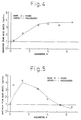
- the parameter H it has been found that there is a clear relationship between the parameter H and the ratio of the meniscus flow velocity Vp in the case where a magnetic field is applied, to the meniscus flow velocity Vo in the case where no magnetic field is applied, i.e., Vp/Vo, and that two tendencies are found in the above relationship.
- one of tendencies is that, as shown in Fig. 4, an increase in parameter H results only in an increase in meniscus flow velocity.
- the other tendency is that, as shown in Fig. 5, when the parameter H is increased, the meniscus flow velocity is first increases and then decreases.
- Equation of parameter H is substituted for H in the equation 2 to determine the meniscus flow velocity Vp, and the magnetic flux density B is regulated to regulate the meniscus flow velocity Vp so as to fall within the range shown in Fig. 1.
- the meniscus flow velocity Vo in the case where no magnetic field is applied, is measured.
- a metal rod is immersed in a molten steel, the load applied to the metal rod is measured with a strain gauge, and the load is converted to flow velocity to determine a desired flow velocity.
- the meniscus flow velocity ratio Vp/Vo for bringing the meniscus flow velocity Vp to the range of from 0.20 to 0.40 m/sec is determined.
- the target range (0.20 to 0.40 m/sec) may be previously divided by the meniscus flow velocity in the case where no magnetic field is applied.
- the resultant value exceeds 1, the meniscus flow velocity should be increased in the casting operation.
- the equation (1) may be used.
- a parameter H for providing the predetermined Vp/Vo value that is, magnetic flux density B, may be determined using the equation (2). Which equation, the equation (1) or the equation (2), should be used depends upon the Vo value.
- the equation (1) when the meniscus flow velocity is small, the equation (1) is used because the degree of increase in the flow velocity is large.
- the equation (2) is used in such a region where the meniscus flow velocity is once increased and then decreased.
- Vp/Vo is less than 1, among parameter H values of not less than 5.3, a parameter H for providing the predetermined Vp/Vo value, that is, magnetic flux density B, may be determined using the equation (2).
- a direct current magnetic field having a magnetic flux density distribution which is substantially uniform in the width direction of the mold in the direction of thickness, enables the meniscus flow velocity to be regulated to the optimal range while bringing the molten steel stream below the magnetic field zone into plug flow.
- the flow velocity of a meniscus stream 8 and the depth of entry of a molten steel stream 7 delivered through a nozzle are determined by the distribution of the molten steel stream delivered through the nozzle in the case where the stream 7 delivered through a nozzle collides against a short-side wall 1A with gradual spreading and is then distributed upward or downward (see Fig. 7 (A)).
- a direct current magnetic field 6 which is substantially uniform in the width direction, is applied in the vicinity of a nozzle hole, the entry of a molten steel stream delivered through a nozzle into a lower portion of the pool is first inhibited by an electromagnetic brake.
- a molten low-carbon aluminum killed steel (AISI: A569-72) was poured into a mold having a size in the direction of internal width (D) of 1 to 2 m and a size in the direction of internal thickness (T) of 0.2 to 0.25 m, and casting was carried out under conditions specified in Table 1 with the average flow velocity (V) of the molten steel delivered through a nozzle being varied in a range of from 0.2 to 1.3 m/sec depending upon the casting speed.
- a magnetic coil was provided on the outer periphery of the mold while taking into consideration the casting speed so that a direct current magnetic field could be uniformly applied in the width direction of the mold.
- Conditions for each casting speed were as follows.
- the meniscus flow velocity V0 in the case where no magnetic field was applied was 7 cm/sec, and the magnetic flux density B for providing a parameter H of not less than 2.6 was 0.15T (tesla).
- the meniscus flow velocity is so low that the degree of acceleration should be large. Therefore, casting was carried out under such a condition that the meniscus flow velocity increases with increasing the magnetic flux density. That is, the molten steel delivery angle of the nozzle and the position of the magnetic field were adjusted so that a stream of the molten steel, delivered through the nozzle, did not directly traverse a high magnetic flux zone, and the H value for bringing the meniscus flow velocity to the range of from 0.20 to 0.23 m/sec was determined using the equation (1).
- the magnetic flux density was 0.16T, and the parameter H was 3.2.
- the magnetic flux density was 0.16T, and the parameter H was 2.6.
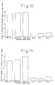
- washing at the front face of a solidified shell based on the acceleration of meniscus flow velocity could prevent the trapping of inclusions in the surface layer of the cast slab, resulting in significantly reduced internal defect index and inclusion defect index in the surface layer as compared with those in comparative examples.
- the meniscus flow velocity V0 was 0.12 m/sec
- the magnetic flux density B for providing a parameter H of not less than 2.6 was 0.18T.
- the meniscus flow velocity in this embodiment is higher than that in the low-speed casting process, the meniscus flow velocity should be further increased. Therefore, casting was carried out under such a condition that, in increasing the magnetic flux density, the meniscus flow velocity was first increased and, thereafter, decreased.
- the molten steel delivery angle of the nozzle and the position of the magnetic field were adjusted so that a stream of the molten steel, delivered through the nozzle, directly traverses a magnetic flux zone.
- Equation (2) which is an equation applied to the case where the H is between a value which provides the maximum meniscus flow velocity and a value which provides a meniscus flow velocity identical to the case wherein no magnetic field is applied, that is, 5.3, was used to determine H (B) for bringing the meniscus flow velocity V p to 0.31 m/sec.
- the magnetic flux densities were respectively 0.28T and 0.34T, and the parameters H were respectively 4.1 and 4.7.
- the surface layer defect and the internal defect of the cast slab could be significantly reduced as compared with those in comparative examples.
- the meniscus flow velocity V0 was 0.50 m/sec
- the magnetic flux density B for providing a parameter H of not less than 2.6 was 0.29T.
- the molten steel delivery angle of the nozzle and the position of the magnetic field were adjusted so as for a stream of the molten steel, delivered through the nozzle, directly traversed a magnetic flux zone, and the equation (2) was used to determined H(B) necessary for bringing the meniscus flow velocity V p to 0.37 m/sec.
- the magnetic flux densities were respectively 0.44T and 0.43T, and the parameters H were respectively 5.8 and 6.0.
- the examples of the present invention could significantly reduce the number of inclusion defects, in the surface of the cast slab, caused by powder entrainment and, further, could reduce a variation in the molten steel surface level, resulting in improved surface appearance. Further, at the same time, a stream of the molten steel below the magnetic field zone could be brought to plug flow, resulting in significantly reduced amount of internal defects in the cast slab.
- the meniscus flow velocity can be stably increased or decreased while bringing a molten steel stream below a magnetic field zone into plug flow according to need, enabling the meniscus flow velocity to be regulated so as to fall within a specific range (0.20 to 0.40 m/sec).
- This makes it possible to prepare a cast slab wherein the defects in the surface layer as well as in the interior thereof has been greatly reduced, that is, a cast slab having an improved quality.
- the present invention can flexibly cope with a change of casting conditions.
- the molten steel stream below the magnetic field zone can be surely brought into plug flow, enabling different steels to be continuously cast without using any iron plate unlike the prior art.
- a deterioration in quality of the cast slab before and after varying the kind of the steel to be cast can be prevented.
- the present invention is very useful in continuous casting.
Landscapes
- Engineering & Computer Science (AREA)
- Mechanical Engineering (AREA)
- Continuous Casting (AREA)
Applications Claiming Priority (1)
| Application Number | Priority Date | Filing Date | Title |
|---|---|---|---|
| PCT/JP1994/000513 WO1995026243A1 (fr) | 1994-03-29 | 1994-03-29 | Procede de commande de flux dans un moule de coulee a l'aide d'un champ magnetique cc |
Publications (3)
| Publication Number | Publication Date |
|---|---|
| EP0707909A1 true EP0707909A1 (fr) | 1996-04-24 |
| EP0707909A4 EP0707909A4 (fr) | 1997-10-29 |
| EP0707909B1 EP0707909B1 (fr) | 1999-06-16 |
Family
ID=14098292
Family Applications (1)
| Application Number | Title | Priority Date | Filing Date |
|---|---|---|---|
| EP94910564A Expired - Lifetime EP0707909B1 (fr) | 1994-03-29 | 1994-03-29 | Procede de commande de flux dans un moule de coulee a l'aide d'un champ magnetique cc |
Country Status (6)
| Country | Link |
|---|---|
| US (1) | US5657816A (fr) |
| EP (1) | EP0707909B1 (fr) |
| JP (1) | JP3188273B2 (fr) |
| CA (1) | CA2163998C (fr) |
| DE (1) | DE69419153T2 (fr) |
| WO (1) | WO1995026243A1 (fr) |
Cited By (3)
| Publication number | Priority date | Publication date | Assignee | Title |
|---|---|---|---|---|
| WO1999011404A1 (fr) * | 1997-09-03 | 1999-03-11 | Abb Ab | Procede et dispositif pour la coulee continue ou semi-continue de metal |
| WO2004050277A1 (fr) * | 2002-11-29 | 2004-06-17 | Abb Ab | Systeme de regulation, produit de programme informatique et dispositif et procede |
| EP1486274A4 (fr) * | 2002-03-01 | 2008-06-04 | Jfe Steel Corp | Procede et appareil de regulation de l'ecoulement d'acier en fusion dans un moule et procede de production de coulees continues |
Families Citing this family (11)
| Publication number | Priority date | Publication date | Assignee | Title |
|---|---|---|---|---|
| JP3125664B2 (ja) | 1996-01-19 | 2001-01-22 | 日本鋼管株式会社 | 極低炭素鋼スラブの連続鋳造方法 |
| JP3388686B2 (ja) | 1997-03-11 | 2003-03-24 | 新日本製鐵株式会社 | 連続鋳造ストランド内の流動制御方法 |
| US6341642B1 (en) | 1997-07-01 | 2002-01-29 | Ipsco Enterprises Inc. | Controllable variable magnetic field apparatus for flow control of molten steel in a casting mold |
| SE523157C2 (sv) * | 1997-09-03 | 2004-03-30 | Abb Ab | Förfarande och anordning för att styra metallflödet vid stränggjutning medelst elektromagnetiska fält |
| JP3275823B2 (ja) | 1998-02-24 | 2002-04-22 | 住友金属工業株式会社 | 広幅薄・中厚鋳片の鋳型内流動制御方法 |
| JP3019859B1 (ja) * | 1999-06-11 | 2000-03-13 | 住友金属工業株式会社 | 連続鋳造方法 |
| SE0301049A0 (en) * | 2002-11-29 | 2004-05-30 | Abb Ab | Control system, computer program product, device and method |
| DE602004005978T2 (de) | 2003-04-11 | 2008-01-17 | Jfe Steel Corp. | Stranggussverfahren für stahl |
| JP2011218435A (ja) * | 2010-04-14 | 2011-11-04 | Nippon Steel Corp | 連続鋳造方法 |
| DE102013101962B3 (de) * | 2013-02-27 | 2014-05-22 | Schuler Pressen Gmbh | Gießvorrichtung und Gießverfahren |
| TWI726000B (zh) † | 2015-11-10 | 2021-05-01 | 美商維蘇威美國公司 | 包含導流器的鑄口 |
Family Cites Families (9)
| Publication number | Priority date | Publication date | Assignee | Title |
|---|---|---|---|---|
| SE436251B (sv) * | 1980-05-19 | 1984-11-26 | Asea Ab | Sett och anordning for omrorning av de icke stelnade partierna av en gjutstreng |
| JP2726096B2 (ja) * | 1989-04-27 | 1998-03-11 | 川崎製鉄株式会社 | 静磁場を用いる鋼の連続鋳造方法 |
| KR930002836B1 (ko) * | 1989-04-27 | 1993-04-10 | 가와사끼 세이데쓰 가부시까가이샤 | 정자장을 이용한 강철의 연속 주조방법 |
| JP2810511B2 (ja) * | 1990-07-31 | 1998-10-15 | 新日本製鐵株式会社 | 溶融金属のメニスカス流速測定方法および装置 |
| JPH04147754A (ja) * | 1990-10-12 | 1992-05-21 | Nippon Steel Corp | 連続鋳造設備の溶鋼流制御装置 |
| JP2990555B2 (ja) * | 1992-04-08 | 1999-12-13 | 新日本製鐵株式会社 | 連続鋳造方法 |
| JP2633769B2 (ja) * | 1992-05-27 | 1997-07-23 | 新日本製鐵株式会社 | 連続鋳造モールド内溶鋼流動制御方法 |
| JP2633764B2 (ja) * | 1992-05-27 | 1997-07-23 | 新日本製鐵株式会社 | 連続鋳造モールド内溶鋼流動制御方法 |
| JP2607332B2 (ja) * | 1992-06-18 | 1997-05-07 | 新日本製鐵株式会社 | 連続鋳造鋳型内溶鋼の流動制御装置 |
-
1994
- 1994-03-29 US US08/549,735 patent/US5657816A/en not_active Expired - Lifetime
- 1994-03-29 DE DE69419153T patent/DE69419153T2/de not_active Expired - Lifetime
- 1994-03-29 WO PCT/JP1994/000513 patent/WO1995026243A1/fr not_active Ceased
- 1994-03-29 EP EP94910564A patent/EP0707909B1/fr not_active Expired - Lifetime
- 1994-03-29 JP JP52507895A patent/JP3188273B2/ja not_active Expired - Lifetime
- 1994-03-29 CA CA002163998A patent/CA2163998C/fr not_active Expired - Lifetime
Cited By (7)
| Publication number | Priority date | Publication date | Assignee | Title |
|---|---|---|---|---|
| WO1999011404A1 (fr) * | 1997-09-03 | 1999-03-11 | Abb Ab | Procede et dispositif pour la coulee continue ou semi-continue de metal |
| EP1486274A4 (fr) * | 2002-03-01 | 2008-06-04 | Jfe Steel Corp | Procede et appareil de regulation de l'ecoulement d'acier en fusion dans un moule et procede de production de coulees continues |
| US7540317B2 (en) | 2002-03-01 | 2009-06-02 | Jfe Steel Corporation | Method and apparatus for controlling flow of molten steel in mold, and method for producing continuous castings |
| US7762311B2 (en) | 2002-03-01 | 2010-07-27 | Jfe Steel Corporation | Method for controlling flow of molten steel in mold and method for continuously producing a cast product |
| US7967058B2 (en) | 2002-03-01 | 2011-06-28 | Jfe Steel Corporation | Apparatus for controlling flow of molten steel in mold |
| WO2004050277A1 (fr) * | 2002-11-29 | 2004-06-17 | Abb Ab | Systeme de regulation, produit de programme informatique et dispositif et procede |
| US7669638B2 (en) | 2002-11-29 | 2010-03-02 | Abb Ab | Control system, computer program product, device and method |
Also Published As
| Publication number | Publication date |
|---|---|
| EP0707909B1 (fr) | 1999-06-16 |
| EP0707909A4 (fr) | 1997-10-29 |
| DE69419153D1 (de) | 1999-07-22 |
| CA2163998C (fr) | 2000-05-23 |
| DE69419153T2 (de) | 2000-03-23 |
| US5657816A (en) | 1997-08-19 |
| JP3188273B2 (ja) | 2001-07-16 |
| WO1995026243A1 (fr) | 1995-10-05 |
Similar Documents
| Publication | Publication Date | Title |
|---|---|---|
| EP0707909B1 (fr) | Procede de commande de flux dans un moule de coulee a l'aide d'un champ magnetique cc | |
| US6315029B1 (en) | Continuous casting method, and device therefor | |
| KR20010023598A (ko) | 전자기장을 사용하여 연속 주조중의 금속흐름을 제어하는방법 및 장치 | |
| EP0550785B1 (fr) | Procédé pour coulée continue | |
| JPWO1995026243A1 (ja) | 直流磁場による鋳型内流動の制御方法 | |
| KR100618362B1 (ko) | 연속 주조 주편의 제조 방법 | |
| US5095969A (en) | Electromagnetic agitating method in mold of continuous casting of slab | |
| EP0930946B1 (fr) | Machine de coulage continu | |
| JP2611594B2 (ja) | 鋼のスラブ用鋳片の製造方法 | |
| JP3300619B2 (ja) | 介在物の少ない鋳片の連続鋳造方法 | |
| JP3399627B2 (ja) | 直流磁界による鋳型内溶鋼の流動制御方法 | |
| CA1334337C (fr) | Utilisation d'un champ magnetique pour controler la coulee dans un panier de coulee | |
| JPH06606A (ja) | 連続鋳造鋳型内溶鋼の流動制御装置 | |
| JPH0275455A (ja) | 連続鋳造方法 | |
| KR960003711B1 (ko) | 연속 슬랩 주조방법 | |
| JP3505077B2 (ja) | 介在物の少ない鋳片の連続鋳造方法 | |
| JP3491099B2 (ja) | 静磁場を用いた鋼の連続鋳造方法 | |
| JPH08187557A (ja) | 電磁場を用いた鋼の連続鋳造方法 | |
| JPH09285854A (ja) | 連続鋳造方法 | |
| JP3147824B2 (ja) | 連続鋳造方法 | |
| JPH06607A (ja) | 連続鋳造鋳型内溶鋼の流動制御装置 | |
| JPH0679424A (ja) | 直流磁場による鋳型内流動の制御方法 | |
| JPH06603A (ja) | 連続鋳造鋳型内溶鋼の流動制御装置 | |
| JPH06604A (ja) | 連続鋳造鋳型内溶鋼の流動制御装置 | |
| JPH05329596A (ja) | 連続鋳造モールド内溶鋼流動制御方法 |
Legal Events
| Date | Code | Title | Description |
|---|---|---|---|
| PUAI | Public reference made under article 153(3) epc to a published international application that has entered the european phase |
Free format text: ORIGINAL CODE: 0009012 |
|
| 17P | Request for examination filed |
Effective date: 19951229 |
|
| AK | Designated contracting states |
Kind code of ref document: A1 Designated state(s): DE FR GB IT |
|
| A4 | Supplementary search report drawn up and despatched | ||
| AK | Designated contracting states |
Kind code of ref document: A4 Designated state(s): DE FR GB IT |
|
| GRAG | Despatch of communication of intention to grant |
Free format text: ORIGINAL CODE: EPIDOS AGRA |
|
| 17Q | First examination report despatched |
Effective date: 19980626 |
|
| GRAG | Despatch of communication of intention to grant |
Free format text: ORIGINAL CODE: EPIDOS AGRA |
|
| GRAG | Despatch of communication of intention to grant |
Free format text: ORIGINAL CODE: EPIDOS AGRA |
|
| GRAH | Despatch of communication of intention to grant a patent |
Free format text: ORIGINAL CODE: EPIDOS IGRA |
|
| GRAH | Despatch of communication of intention to grant a patent |
Free format text: ORIGINAL CODE: EPIDOS IGRA |
|
| GRAA | (expected) grant |
Free format text: ORIGINAL CODE: 0009210 |
|
| AK | Designated contracting states |
Kind code of ref document: B1 Designated state(s): DE FR GB IT |
|
| REF | Corresponds to: |
Ref document number: 69419153 Country of ref document: DE Date of ref document: 19990722 |
|
| ET | Fr: translation filed | ||
| ITF | It: translation for a ep patent filed | ||
| PLBQ | Unpublished change to opponent data |
Free format text: ORIGINAL CODE: EPIDOS OPPO |
|
| PLBI | Opposition filed |
Free format text: ORIGINAL CODE: 0009260 |
|
| PLBF | Reply of patent proprietor to notice(s) of opposition |
Free format text: ORIGINAL CODE: EPIDOS OBSO |
|
| 26 | Opposition filed |
Opponent name: HOOGOVENS STAAL BV Effective date: 20000315 |
|
| PLBQ | Unpublished change to opponent data |
Free format text: ORIGINAL CODE: EPIDOS OPPO |
|
| PLAB | Opposition data, opponent's data or that of the opponent's representative modified |
Free format text: ORIGINAL CODE: 0009299OPPO |
|
| R26 | Opposition filed (corrected) |
Opponent name: HOOGOVENS STAAL BV Effective date: 20000315 |
|
| PLBF | Reply of patent proprietor to notice(s) of opposition |
Free format text: ORIGINAL CODE: EPIDOS OBSO |
|
| PLBF | Reply of patent proprietor to notice(s) of opposition |
Free format text: ORIGINAL CODE: EPIDOS OBSO |
|
| PLBF | Reply of patent proprietor to notice(s) of opposition |
Free format text: ORIGINAL CODE: EPIDOS OBSO |
|
| PLBL | Opposition procedure terminated |
Free format text: ORIGINAL CODE: EPIDOS OPPC |
|
| PLBL | Opposition procedure terminated |
Free format text: ORIGINAL CODE: EPIDOS OPPC |
|
| PLBM | Termination of opposition procedure: date of legal effect published |
Free format text: ORIGINAL CODE: 0009276 |
|
| STAA | Information on the status of an ep patent application or granted ep patent |
Free format text: STATUS: OPPOSITION PROCEDURE CLOSED |
|
| 27C | Opposition proceedings terminated |
Effective date: 20010215 |
|
| REG | Reference to a national code |
Ref country code: GB Ref legal event code: IF02 |
|
| PGFP | Annual fee paid to national office [announced via postgrant information from national office to epo] |
Ref country code: IT Payment date: 20120321 Year of fee payment: 19 |
|
| REG | Reference to a national code |
Ref country code: DE Ref legal event code: R082 Ref document number: 69419153 Country of ref document: DE Representative=s name: VOSSIUS & PARTNER PATENTANWAELTE RECHTSANWAELT, DE Effective date: 20130227 Ref country code: DE Ref legal event code: R082 Ref document number: 69419153 Country of ref document: DE Representative=s name: VOSSIUS & PARTNER, DE Effective date: 20130227 Ref country code: DE Ref legal event code: R081 Ref document number: 69419153 Country of ref document: DE Owner name: NIPPON STEEL & SUMITOMO METAL CORPORATION, JP Free format text: FORMER OWNER: NIPPON STEEL CORP., TOKIO/TOKYO, JP Effective date: 20130227 |
|
| PGFP | Annual fee paid to national office [announced via postgrant information from national office to epo] |
Ref country code: FR Payment date: 20130325 Year of fee payment: 20 Ref country code: DE Payment date: 20130327 Year of fee payment: 20 Ref country code: GB Payment date: 20130327 Year of fee payment: 20 |
|
| REG | Reference to a national code |
Ref country code: FR Ref legal event code: CD Owner name: NIPPON STEEL & SUMITOMO METAL CORPORATION, JP Effective date: 20130913 Ref country code: FR Ref legal event code: CA Effective date: 20130913 |
|
| REG | Reference to a national code |
Ref country code: DE Ref legal event code: R071 Ref document number: 69419153 Country of ref document: DE |
|
| REG | Reference to a national code |
Ref country code: DE Ref legal event code: R071 Ref document number: 69419153 Country of ref document: DE |
|
| REG | Reference to a national code |
Ref country code: GB Ref legal event code: PE20 Expiry date: 20140328 |
|
| PG25 | Lapsed in a contracting state [announced via postgrant information from national office to epo] |
Ref country code: GB Free format text: LAPSE BECAUSE OF EXPIRATION OF PROTECTION Effective date: 20140328 |
|
| PG25 | Lapsed in a contracting state [announced via postgrant information from national office to epo] |
Ref country code: DE Free format text: LAPSE BECAUSE OF EXPIRATION OF PROTECTION Effective date: 20140401 |