EP0707912B1 - Dispositif d'usinage d'extrémités de tubes - Google Patents
Dispositif d'usinage d'extrémités de tubes Download PDFInfo
- Publication number
- EP0707912B1 EP0707912B1 EP95250232A EP95250232A EP0707912B1 EP 0707912 B1 EP0707912 B1 EP 0707912B1 EP 95250232 A EP95250232 A EP 95250232A EP 95250232 A EP95250232 A EP 95250232A EP 0707912 B1 EP0707912 B1 EP 0707912B1
- Authority
- EP
- European Patent Office
- Prior art keywords
- sliders
- push rods
- tool head
- cam
- tube
- Prior art date
- Legal status (The legal status is an assumption and is not a legal conclusion. Google has not performed a legal analysis and makes no representation as to the accuracy of the status listed.)
- Expired - Lifetime
Links
- 238000005520 cutting process Methods 0.000 claims description 11
- 238000003754 machining Methods 0.000 claims description 6
- 238000006073 displacement reaction Methods 0.000 claims description 5
- 230000001360 synchronised effect Effects 0.000 claims description 2
- 230000005540 biological transmission Effects 0.000 description 5
- 239000000969 carrier Substances 0.000 description 3
- 230000007935 neutral effect Effects 0.000 description 3
- 238000004519 manufacturing process Methods 0.000 description 2
- 230000009467 reduction Effects 0.000 description 2
- 230000002411 adverse Effects 0.000 description 1
- 238000010276 construction Methods 0.000 description 1
- 238000009792 diffusion process Methods 0.000 description 1
- 238000009826 distribution Methods 0.000 description 1
- 230000002349 favourable effect Effects 0.000 description 1
- 210000003746 feather Anatomy 0.000 description 1
- 230000004886 head movement Effects 0.000 description 1
- 230000002441 reversible effect Effects 0.000 description 1
- 230000000630 rising effect Effects 0.000 description 1
- 238000005096 rolling process Methods 0.000 description 1
- 230000004936 stimulating effect Effects 0.000 description 1
- 238000003860 storage Methods 0.000 description 1
Images



Classifications
-
- B—PERFORMING OPERATIONS; TRANSPORTING
- B23—MACHINE TOOLS; METAL-WORKING NOT OTHERWISE PROVIDED FOR
- B23B—TURNING; BORING
- B23B29/00—Holders for non-rotary cutting tools; Boring bars or boring heads; Accessories for tool holders
- B23B29/24—Tool holders for a plurality of cutting tools, e.g. turrets
-
- B—PERFORMING OPERATIONS; TRANSPORTING
- B23—MACHINE TOOLS; METAL-WORKING NOT OTHERWISE PROVIDED FOR
- B23G—THREAD CUTTING; WORKING OF SCREWS, BOLT HEADS, OR NUTS, IN CONJUNCTION THEREWITH
- B23G2240/00—Details of equipment for threading other than threading tools, details of the threading process
- B23G2240/04—Compensation of centrifugal force
-
- Y—GENERAL TAGGING OF NEW TECHNOLOGICAL DEVELOPMENTS; GENERAL TAGGING OF CROSS-SECTIONAL TECHNOLOGIES SPANNING OVER SEVERAL SECTIONS OF THE IPC; TECHNICAL SUBJECTS COVERED BY FORMER USPC CROSS-REFERENCE ART COLLECTIONS [XRACs] AND DIGESTS
- Y10—TECHNICAL SUBJECTS COVERED BY FORMER USPC
- Y10T—TECHNICAL SUBJECTS COVERED BY FORMER US CLASSIFICATION
- Y10T408/00—Cutting by use of rotating axially moving tool
- Y10T408/83—Tool-support with means to move Tool relative to tool-support
- Y10T408/85—Tool-support with means to move Tool relative to tool-support to move radially
- Y10T408/858—Moving means including wedge, screw or cam
-
- Y—GENERAL TAGGING OF NEW TECHNOLOGICAL DEVELOPMENTS; GENERAL TAGGING OF CROSS-SECTIONAL TECHNOLOGIES SPANNING OVER SEVERAL SECTIONS OF THE IPC; TECHNICAL SUBJECTS COVERED BY FORMER USPC CROSS-REFERENCE ART COLLECTIONS [XRACs] AND DIGESTS
- Y10—TECHNICAL SUBJECTS COVERED BY FORMER USPC
- Y10T—TECHNICAL SUBJECTS COVERED BY FORMER US CLASSIFICATION
- Y10T409/00—Gear cutting, milling, or planing
- Y10T409/30—Milling
- Y10T409/306664—Milling including means to infeed rotary cutter toward work
- Y10T409/306776—Axially
- Y10T409/307056—Axially and laterally
- Y10T409/307112—Simultaneously
Definitions
- the invention relates to a device for processing pipe ends, in particular for Cutting threaded connections where the cutting tools are radial to the pipe adjustably arranged in a tool head which is coaxial around the fixed clamped pipe end rotates, the adjusting movement of the in as a slide trained tool holders clamped tools against the pipe axially parallel to the pipe and evenly distributed over its circumference Push rods takes place, the distal ends of the tube end at a common coaxial to the tool head axis are displaceable frames and their other End areas are provided with helical gears that correspond to Gears on the deflection means are in operative connection, via which the axially parallel Feed movement of the push rods in a synchronous radial displacement movement of the Slider for setting the cutting tools can be implemented.
- thread cutting machines For processing pipe ends, especially for cutting threaded connections, for example on tubing and casing pipes, thread cutting machines are known work with a clamped tube and rotating tools.
- the pipe thread is usually produced when the tools are passed over the pipe end once, whereby the movements of the tools are computer-numerically controlled.
- the appropriate machines must be designed so that particularly tight Thread tolerances can be achieved. These machines are particularly important the actual tool head in which the tools can be positioned against the pipe are led.
- the pipe itself is brought to the machine in a defined position and, after the exact position of the pipe end is reached, the cutting tool feed switched on.
- the machining tools on the tool head are evenly circumferential distributed displaceable, the number of tools used is arbitrary is, but in most cases six tools are provided, three of which Pre-turning tools for machining the cone and three combined finished turning tools with the thread chucks centrally in the rotating tool head are arranged. In each case three tools offset by 120 ° become the same and the other tools moved in the opposite direction.
- 1000 rpm creates very high centrifugal forces on the mobile Masses that exactly keep the feed forces to be kept as small as possible counteract positioning tools.
- a device of the type described in the opening paragraph is known from DE-A-3440398. At the solution described there, however, it is not possible to redirect the positioning forces for the cutting tools from the push rods to the sliders with no force in relation to to achieve effective centrifugal forces. Apart from that, the solution described there is constructively very complex.
- the deflection means are rotationally mounted and over the Teeth of the push rods acting on them are rotatable.
- the deflecting means Pipe end coaxially encompassing rotatably mounted ring is provided, which of the Push rods is rotatable and the end face facing the pipe end Has cam tracks that cooperate with guide elements on the sliders and by which the slide can be moved radially when the ring is rotated.
- the Cam tracks that have a spiral pitch, for example, move the Tool carrier with the tools, depending on the rotation of the rotating ring the toothed push rods radially to the tube, the push rods in turn in the engage the corresponding external toothing on the ring.
- each two adjacent cam tracks different Have directions of incline can by rotating the ring in one direction Reversal of movement of every second slide can be achieved. So it becomes possible at six sliders provided and three sliders radially against the pipe simultaneously move three other slides back from the pipe using other tools.
- the proposed solution is characterized by complete centrifugal force compensation in Center position of all sliders via the cam ring.
- cam tracks preferably run like strips on the end face of the ring and each cam track is between two preloadable bearings that are mounted on the slide in a floating manner Rolls clamped. Due to the pre-tensioning of the rollers, play-free tracking is possible Cam tracks possible, with the force balance and the storage of rollers and Ring smooth and accurate movements can be achieved.
- a device for processing pipe ends provided that the helical gears on the push rods on two themselves Opposite long sides are arranged and with the push rods on both sides arranged racks correspond, the direction of extension transverse to Push rod and runs in the direction of the axis of movement of the slide on which the Racks are attached.
- the longitudinal movements of the Push rods over the helical teeth on the push rods directly in transverse to it running, attached to the sliders racks initiated so that when Longitudinal displacement of the push rods in the transverse direction against the pipe or be moved away from the pipe.
- cam spindles are provided which are radial in a common plane axes extending to the tool head axis are rotatably mounted in the tool head and at least over a partial area of its circumference with an increasing in the circumferential direction
- Cam track are provided, through which the slide can be moved in the direction of attack.
- the axial force of the push rods is mechanically favorable in a rotation of the deflection means implemented and in the linear movement of the slide forwarded.
- the cam spindles themselves are in through the teeth of the push rods Rotation offset, the toothing of the push rods in corresponding Gears on the circumference of the cam spindle.
- Rollers which can be adjusted against one another in pairs are preferably flying on the slides arranged, each including a cam track between them.
- the cam spindles Adjacent slides are in opposite directions from the push rods acted upon, so that the centrifugal force compensation in this embodiment of the invention between two adjacent opposing spools via the one through the common Frame connected axial push rods is advantageously possible.
- the employability and Preloading the rollers as a radial transmission element ensures zero play Power transmission is directly related to the quality and performance of the device benefits. There is no backlash in the sliders because of centrifugal and Machining forces always act on the transmission elements in one direction.
- the Tool carriers via a preloaded spring system of the different types radial displacement positions of the tool carrier from the centrifugal forces of the moving parts arising differential forces can be relieved, the spring forces and spring characteristics of Springs on the linearly acting differential forces and their directions of action are coordinated.
- the spring system can be directly on the tool carriers as well also be provided on the frame and / or the push rod.
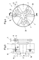
- FIG. 1 denotes the tool head, around its tool head axis 2 the tool carriers in the form of sliders 3 are arranged evenly distributed. Via a sliding 4 frame 5, the ends of the frame 5 are at 6 Articulated push rods 7 simultaneously in the longitudinal axis direction 8 slidable. The push rods 7 are in the region of their ends 9 Helical gears 10 provided, which in corresponding helical gears 11th engage a ring 12 which the (not shown) pipe end and Tool head axis 2 coaxially engages and is roller-supported at 13.
- cam tracks 14 are formed, as can be seen better in FIG. 2. These cam tracks correspond to two rollers 15 which can be set against one another, 16, which are overhung on the tool carrier 3.
- Helical gears 10 and 11 in the push rods 7 and on the outer circumference the ring 12 is a twisting of the ring with the strip-like cam tracks 14, whereby the rollers 15, 16, rolling on the cam tracks 14 without play, the Force the tool holder 3 to move radially towards the tool head axis 2 or move away from it.
- the frame 5 can first be seen in accordance with FIG at 6 the push rods 7 are articulated, three of which on the circumference of the Tool head 1 are provided distributed.
- the push rods 7 are in their End regions 9 in turn are provided with helical gears 10, but this time on the two opposite sides of the push rod 7.
- the toothing correspond to corresponding toothings in the push rod 7 on both sides arranged racks 18, which in turn are attached to the slide 3.
- Axial movement of the push rods 7 in the direction of arrow 4 causes due to the teeth a movement of the slide 3 with the tools 17 in the direction of arrow 19.
- FIG. 5 the same parts are labeled identically.
- the one with helical gears provided push rods 7 are this time with serving as a deflecting means
- Paired cam spindles 22 which extend radially to the tool head axis 2 Axes of rotation 23 are rotatably mounted in the tool head 1.
- the cam spindles point on its circumference one corresponding to the toothing 10 of the push rods Helical toothing 24 so that when the push rods 7 are moved in the direction of the arrow 4 the cam spindles 22 are set in rotary movements.
- the engagement between Push rod 7 and teeth 10 can be biased via eccentric, so that at opposing movement and direction of force from machining and centrifugal forces same stroke direction of the push rods 7 freedom from play is guaranteed.
- Each cam spindle 22 is connected to one of a portion of its circumference Circumferential direction rising cam track 25 to see on both sides and Rollers 26 and 27, which can be adjusted in pairs against one another, rest without play. These roles are in turn mounted on the slide 3 overhung and thus cause a backlash Move this slide 3 radially to the (not shown) pipe end when the Cam spindles are set in rotation.
- By choosing the direction of the slope adjacent cam spindles 22 or opposite arrangement of the Push rods to the center toothing make it possible to have adjacent ones Guide cam spindles in different directions of movement when over the Push rod 7, the cam spindles are rotated. Because of the backlash There are no adjustable rollers and gears in the entire tool head Reverse game.
- the weight is balanced by a preloaded spring system with three springs 28, corresponding to the maximum differential forces occurring in their Directions of action are prestressed.
- the springs 28 are arranged so that they are in the neutral position of the tools 17, that is when all the sliders 3 are in the Middle position, are relaxed.
- the tension of the springs 28 is linear at the same time linear reduction of the differential forces.
- the springs 28 are on one Rod 29 slidably connected to the frame 5, three of which distributed on the tool head 1 parallel to the push rods 7.
- the Rods 29 extend into bores 35 in the tool head 1, which on the Frame 5 remote end are closed and a stop 30 for the Form rod 29.
- Each rod 29 is at its free end with a spring supporting collar 31 provided.
- the feather of one Ring 32 freely displaceable on the rod, which in turn is supported by a Tool head 1 attached sleeve 33 is prevented from the tool head 1 leave.
- the sleeve 33 is in its inner diameter encompassing the rod 29 dimensioned that one attached to the frame 5 and pushed over the rod 29 Bush 34 can penetrate the sleeve 33 and the ring 28 supporting the spring 32 can move such that the spring 28 is compressed when the The collar 31 of the rod 29 has reached the stop 30.
- the spring 28 in biased in the opposite direction when the frame 5 with the push rods 7 and the rods 29 (to the right in the drawing) is moved. Then push the collar 31 on the rod 29, the spring 28 against the sliding ring 32, the limited by the sleeve 33 in its displacement, the spring 28 between them and the federal government 31.
- In the neutral position of the slide 3 is the relaxed Spring 28 with the collar 31 on the stop 30 and on the ring 32 and is despite certain pre-tension is force-neutral in relation to the frame 5.
Landscapes
- Engineering & Computer Science (AREA)
- Mechanical Engineering (AREA)
- Turning (AREA)
- Drilling And Boring (AREA)
Claims (11)
- Dispositif pour usiner des extrémités de tube, en particulier pour couper des raccords filetés, dans lequel les outils de coupe sont agencés de façon déplaçable dans une tête d'outil, en pouvant être approchés radialement vers le tube, tête qui tourne coaxialement autour de l'extrémité de tube solidement serrée, le mouvement d'approche des outils montés dans des supports d'outil réalisés comme coulisseaux étant effectué par rapport au tube par l'intermédiaire de barres de poussée agencées parallèlement à l'axe par rapport au tube et de façon régulièrement répartie sur sa périphérie, dont les extrémités éloignées de l'extrémité du tube sont articulées sur un bâti commun déplaçable coaxialement par rapport à l'axe de la tête d'outil et dont les autres zones d'extrémité sont munies de dentures hélicoïdales (10), qui sont en liaison active sur des moyens de renvoi dans des dentures correspondantes (11, 18, 24), par l'intermédiaire desquelles le déplacement d'avance, parallèle à l'axe, des barres de poussée peut être transformé en un déplacement radial synchrone des coulisseaux pour l'approche des outils de coupe,
caractérisé en ce que les moyens de renvoi sont montés en rotation et peuvent être tournés par l'intermédiaire des dentures des barres de poussée agissant sur ceux-ci. - Dispositif selon la revendication 1,
caractérisé en ce que, comme moyens de renvoi, il est prévu une bague (12) montée rotative, entourant coaxialement l'extrémité du tube, qui peut être tournée par les barres de poussée (7) et qui présente, sur sa face frontale en regard de l'extrémité du tube, des voies à cames (14), qui coopèrent avec des éléments de guidage sur les coulisseaux (3) et grâce auxquelles, par rotation de la bague (12), les coulisseaux (3) peuvent être déplacés radialement. - Dispositif selon la revendication 2,
caractérisé en ce que, pour des coulisseaux (3) agencés en nombre entier sur la tête d'outil (1), à chaque fois deux voies à cames voisines (14) présentent différentes directions de pente. - Dispositif selon les revendications 1 à 3,
caractérisé en ce que les voies à cames (14) s'étendent sous forme de barrettes sur la face frontale de la bague (12) et chaque voie à cames (14) est serrée entre deux rouleaux (15, 16), pouvant être précontraints, montés de façon mobile sur le coulisseau (3). - Dispositif selon la revendication 1,
caractérisé en ce que les dentures hélicoïdales (10, 11, 18, 24) sont agencées sur les barres de poussée (7) sur deux faces longitudinales opposées et correspondent avec des crémaillères (18) agencées des deux côtés des barres de poussée (7), dont la direction d'extension s'étend transversalement à la barre de poussée (7) et en direction de l'axe de déplacement des coulisseaux (3), sur lesquels sont fixées les crémaillères (18). - Dispositif selon la revendication 5,
caractérisé en ce que, pour des coulisseaux (3) agencés en nombre entier sur la tête d'outil (1), uniquement les crémaillères (18) de chaque second coulisseau (3) correspondent avec une barre de poussée (7), et en ce que les coulisseaux voisins (3) sont reliés ensemble par l'intermédiaire, à chaque fois, d'une roue à denture frontale (20), en ce que la denture de roue frontale correspond simultanément avec à chaque fois une crémaillère (18) sur chaque coulisseau (3). - Dispositif selon la revendication 1,
caractérisé en ce que, comme moyens de renvoi, sont prévus des broches à came (22) qui sont montées de façon rotative dans la tête d'outil (1) autour d'axes (23) s'étendant dans un plan commun radialement par rapport à l'axe (2) de la tête d'outil et sont munies, au moins sur une zone partielle de leur périphérie, d'une voie à cames (25) montant en direction périphérique, grâce à laquelle les coulisseaux (3) peuvent être déplacés dans la direction d'approche. - Dispositif selon la revendication 7,
caractérisé en ce que, sur les coulisseaux (3), sont agencés, de façon mobile, des rouleaux (26, 27) pouvant être approchés l'un de l'autre par paire, qui, à chaque fois, englobent entre eux une voie à cames (25). - Dispositif selon les revendications 7 et 8,
caractérisé en ce que les broches à came (22) de coulisseaux voisins (3) peuvent être sollicitées par les barres de poussée (7) dans des sens opposés de rotation. - Dispositif selon une ou plusieurs des revendications 1 à 9,
caractérisé en ce que les dentures des barres de poussée (7)/roues dentées (20) peuvent être réglées sans jeu par l'intermédiaire d'excentriques. - Dispositif selon une ou plusieurs des revendications 1 à 10,
caractérisé en ce que les coulisseaux (3) peuvent être déchargés des forces différentielles créées à partir des forces centrifuges des pièces mobiles pour des positions de déplacement radiales différentes des coulisseaux par l'intermédiaire d'un système élastique pouvant être précontraint, les élasticités et les courbes caractéristiques des ressorts (28) étant accordées aux forces différentielles variant de façon linéaire et à leurs directions d'action.
Applications Claiming Priority (2)
| Application Number | Priority Date | Filing Date | Title |
|---|---|---|---|
| DE4438818 | 1994-10-20 | ||
| DE4438818A DE4438818A1 (de) | 1994-10-20 | 1994-10-20 | Vorrichtung zur Bearbeitung von Rohrenden |
Publications (2)
| Publication Number | Publication Date |
|---|---|
| EP0707912A1 EP0707912A1 (fr) | 1996-04-24 |
| EP0707912B1 true EP0707912B1 (fr) | 2001-06-06 |
Family
ID=6532103
Family Applications (1)
| Application Number | Title | Priority Date | Filing Date |
|---|---|---|---|
| EP95250232A Expired - Lifetime EP0707912B1 (fr) | 1994-10-20 | 1995-09-22 | Dispositif d'usinage d'extrémités de tubes |
Country Status (4)
| Country | Link |
|---|---|
| US (1) | US5662524A (fr) |
| EP (1) | EP0707912B1 (fr) |
| JP (1) | JPH08206921A (fr) |
| DE (2) | DE4438818A1 (fr) |
Families Citing this family (24)
| Publication number | Priority date | Publication date | Assignee | Title |
|---|---|---|---|---|
| DE19605021A1 (de) * | 1996-01-31 | 1997-08-07 | Mannesmann Ag | Maschine zum Trennen von Rohren |
| FR2804890B1 (fr) * | 2000-02-14 | 2002-04-12 | Thierry Monnet | Dispositif de percage radial pour tour |
| DE102004004498A1 (de) | 2004-01-29 | 2005-08-18 | Sms Meer Gmbh | Vorrichtung zur Bearbeitung von Rohrenden, insbesondere zum Schneiden von Gewindeanschlüssen |
| CN100345656C (zh) * | 2004-12-17 | 2007-10-31 | 徐森良 | 便捷式铰牙固管器 |
| US8186249B2 (en) * | 2008-06-30 | 2012-05-29 | Pratt & Whitney Canada Corp. | Three point turning machine |
| CN102266956A (zh) * | 2010-06-04 | 2011-12-07 | 无锡百纳容器有限公司 | 一种用于加工天然气瓶口部的切削车刀底盘 |
| DE102011009794A1 (de) * | 2011-01-29 | 2012-08-02 | Sms Meer Gmbh | Rohrendenbearbeitungsmaschine |
| CN102950299B (zh) * | 2012-11-28 | 2015-04-08 | 安徽新源石油化工技术开发有限公司 | 一种摆动调节式浮动刀架 |
| KR101471166B1 (ko) * | 2013-02-21 | 2014-12-11 | 한국기계연구원 | 터닝 기반의 융복합 가공장치 |
| CN104174939A (zh) * | 2013-05-21 | 2014-12-03 | 李洪明 | 一种双向双工位攻丝机 |
| KR101407328B1 (ko) * | 2014-02-07 | 2014-06-13 | 디씨에스이엔지 주식회사 | 원심력을 이용하여 절삭툴의 진입 절삭력을 제공하는 오비탈식 절삭장치 |
| CN104551270B (zh) * | 2014-12-19 | 2017-04-12 | 张彩花 | 一种可自动回弹的套丝机 |
| CN105414688B (zh) * | 2015-11-30 | 2019-03-19 | 浙江德清科赛塑料制品有限公司 | 万向节的车削刀具 |
| CN105397571A (zh) * | 2015-12-04 | 2016-03-16 | 海宁久久胶塑有限公司 | 集装箱连接件加工设备 |
| CN105522401B (zh) * | 2016-01-18 | 2018-05-11 | 安徽原上草节能环保科技有限公司 | 具有红外检测单元的仪表机床 |
| CN105478869B (zh) * | 2016-01-18 | 2018-03-27 | 浙江华旭实业有限公司 | 多刀位数控铣床 |
| CN108380986B (zh) * | 2018-03-17 | 2024-04-16 | 昆山仁硕机械制造有限公司 | 一种加工位置自适应调整的攻牙装置 |
| CN109668489B (zh) * | 2018-12-28 | 2020-11-03 | 盛瑞传动股份有限公司 | 一种凸轮轴轴颈测量用卡规 |
| CN111922451A (zh) * | 2020-08-01 | 2020-11-13 | 上海格兰克林(集团)有限公司 | 一种单螺杆空压机螺杆加工设备 |
| CH718197B1 (fr) * | 2020-12-21 | 2024-12-30 | Esco Sa | Unité d'usinage à tête rotative. |
| JP7610258B2 (ja) * | 2021-05-17 | 2025-01-08 | エヌティーツール株式会社 | タレット、工具ホルダ取付け方法および工具ホルダ |
| CN113560680B (zh) * | 2021-07-31 | 2022-09-16 | 浙江龙华工具有限公司 | 一种自动退刀的套丝机板牙头总成 |
| CN113865959B (zh) * | 2021-09-27 | 2022-07-26 | 吉林大学 | 一种使用方便的肝癌组织病理检查用辅助设备 |
| CN116275312B (zh) * | 2022-12-12 | 2023-12-19 | 中建八局第二建设有限公司 | 一种建筑自动化钢筋直螺纹套丝机 |
Family Cites Families (10)
| Publication number | Priority date | Publication date | Assignee | Title |
|---|---|---|---|---|
| US3073185A (en) * | 1959-12-21 | 1963-01-15 | Baldwin Lima Hamilton Corp | Boring mill |
| DE1913377A1 (de) * | 1969-03-17 | 1970-09-24 | Richard Sauter | Drehautomat |
| DE2642965C2 (de) * | 1976-09-24 | 1982-07-22 | Gustav Wagner Maschinenfabrik, 7410 Reutlingen | Dreh- und Einstechkopf |
| US4289430A (en) * | 1979-03-14 | 1981-09-15 | Fairfield Machine Company | Method and apparatus for simultaneously boring and turning upset pipe end |
| DE3000055A1 (de) * | 1980-01-03 | 1981-08-06 | Ernst Dipl.-Ing. Dr.techn. Steyrermühl Linsinger | Maschine zum spanenden bearbeiten ruhender zylindrischer werkstuecke |
| DE3237587A1 (de) * | 1982-10-09 | 1984-04-12 | Paul Forkardt GmbH & Co KG, 4000 Düsseldorf | Vorrichtung zur herstellung von gewindeanschluessen an grossrohren |
| AT379096B (de) * | 1983-12-13 | 1985-11-11 | Heid Ag Maschf | Umlaufender bearbeitungskopf |
| DE58909714D1 (de) * | 1989-06-15 | 1996-09-26 | Kieserling & Albrecht | Drehangetriebene Spindel |
| US5231859A (en) * | 1992-03-03 | 1993-08-03 | Trimble House Corporation | Fluting machine |
| US5480271A (en) * | 1994-05-13 | 1996-01-02 | Power House Tool, Inc. | Adjustable die head |
-
1994
- 1994-10-20 DE DE4438818A patent/DE4438818A1/de not_active Withdrawn
-
1995
- 1995-09-22 DE DE59509318T patent/DE59509318D1/de not_active Expired - Fee Related
- 1995-09-22 EP EP95250232A patent/EP0707912B1/fr not_active Expired - Lifetime
- 1995-10-20 JP JP7297842A patent/JPH08206921A/ja active Pending
- 1995-10-20 US US08/546,490 patent/US5662524A/en not_active Expired - Fee Related
Also Published As
| Publication number | Publication date |
|---|---|
| JPH08206921A (ja) | 1996-08-13 |
| US5662524A (en) | 1997-09-02 |
| DE59509318D1 (de) | 2001-07-12 |
| EP0707912A1 (fr) | 1996-04-24 |
| DE4438818A1 (de) | 1996-05-02 |
Similar Documents
| Publication | Publication Date | Title |
|---|---|---|
| EP0707912B1 (fr) | Dispositif d'usinage d'extrémités de tubes | |
| DE2551250A1 (de) | Werkzeugmaschine und fraeswerkzeug zum bearbeiten der zapfen einer kurbelwelle nach dem wirbelverfahren | |
| DE2613269C3 (fr) | ||
| EP2011595B1 (fr) | machine-outil avec un agencement de chariot | |
| DE69938449T2 (de) | Ziehvorrichtung mit spindelmechanismus | |
| DE2556227C3 (de) | Spannfutter | |
| DE4115758C2 (de) | Wälzschraubtrieb | |
| EP3159068B1 (fr) | Banc de formage de pression/d'emboutissage et procede de pression/d'emboutissage | |
| DE3502774A1 (de) | Linearantriebseinheit | |
| DE3002383C3 (de) | Reibrollgetriebe zum Umwandeln einer Drehbewegung in eine Längsbewegung und umgekehrt | |
| CH665894A5 (de) | Linear-antriebsvorrichtung. | |
| DE2245994A1 (de) | Mehrspindel-drehautomat | |
| DE4428049C2 (de) | Werkzeugkopf für Rohrgewindeschneidmaschinen | |
| DE3809400A1 (de) | Antriebsvorrichtung zum verschieben eines beweglichen maschinenteils, insbesondere an schleifmaschinen | |
| DE2718731A1 (de) | Werkzeugmaschine, insbesondere schleifmaschine | |
| DD200364A1 (de) | Schaelmaschine | |
| EP3380739B1 (fr) | Procédé de fabrication d'un composant solide et composant solide | |
| DE4137923A1 (de) | Werkzeugkopf fuer eine vorrichtung zum herstellen von drehteilen | |
| DE2651174B2 (de) | Spann- und Führungseinrichtung für langgestreckte, axialbewegte Werkstücke | |
| DE9103358U1 (de) | Anordnung zum Umformen einer Ronde aus Metall durch Drücken | |
| DE1552412A1 (de) | Querschlitten-Antrieb fuer Mehrspindel-Automaten | |
| DE19700095A1 (de) | Biegeaggregat | |
| DE2259120A1 (de) | Verfahren zum aussenraeumen von werkstuecken und vorrichtung zur durchfuehrung des verfahrens | |
| DE10244483A1 (de) | Profilwalzmaschine mit Kraftrahmen zum Walzen mit außenverzahnten Rundwalzwerkzeugen | |
| EP0483471A2 (fr) | Convertisseur de mouvement pour la transformation d'un mouvement de rotation en entrée en un mouvement de translation en sortie |
Legal Events
| Date | Code | Title | Description |
|---|---|---|---|
| PUAI | Public reference made under article 153(3) epc to a published international application that has entered the european phase |
Free format text: ORIGINAL CODE: 0009012 |
|
| 17P | Request for examination filed |
Effective date: 19960221 |
|
| AK | Designated contracting states |
Kind code of ref document: A1 Designated state(s): DE FR GB IT |
|
| 17Q | First examination report despatched |
Effective date: 19970624 |
|
| RAP1 | Party data changed (applicant data changed or rights of an application transferred) |
Owner name: SMS DEMAG AG |
|
| GRAG | Despatch of communication of intention to grant |
Free format text: ORIGINAL CODE: EPIDOS AGRA |
|
| GRAG | Despatch of communication of intention to grant |
Free format text: ORIGINAL CODE: EPIDOS AGRA |
|
| GRAH | Despatch of communication of intention to grant a patent |
Free format text: ORIGINAL CODE: EPIDOS IGRA |
|
| GRAH | Despatch of communication of intention to grant a patent |
Free format text: ORIGINAL CODE: EPIDOS IGRA |
|
| GRAA | (expected) grant |
Free format text: ORIGINAL CODE: 0009210 |
|
| AK | Designated contracting states |
Kind code of ref document: B1 Designated state(s): DE FR GB IT |
|
| GBT | Gb: translation of ep patent filed (gb section 77(6)(a)/1977) |
Effective date: 20010606 |
|
| REF | Corresponds to: |
Ref document number: 59509318 Country of ref document: DE Date of ref document: 20010712 |
|
| ITF | It: translation for a ep patent filed | ||
| ET | Fr: translation filed | ||
| REG | Reference to a national code |
Ref country code: GB Ref legal event code: IF02 |
|
| PLBE | No opposition filed within time limit |
Free format text: ORIGINAL CODE: 0009261 |
|
| STAA | Information on the status of an ep patent application or granted ep patent |
Free format text: STATUS: NO OPPOSITION FILED WITHIN TIME LIMIT |
|
| 26N | No opposition filed |
Opponent name: CASTRIP LLP(A US COMPANY REGISTERED IN DELAWARE) C Effective date: 20020827 |
|
| PGFP | Annual fee paid to national office [announced via postgrant information from national office to epo] |
Ref country code: GB Payment date: 20020904 Year of fee payment: 8 |
|
| PGFP | Annual fee paid to national office [announced via postgrant information from national office to epo] |
Ref country code: FR Payment date: 20020909 Year of fee payment: 8 |
|
| PG25 | Lapsed in a contracting state [announced via postgrant information from national office to epo] |
Ref country code: GB Free format text: LAPSE BECAUSE OF NON-PAYMENT OF DUE FEES Effective date: 20030922 |
|
| GBPC | Gb: european patent ceased through non-payment of renewal fee |
Effective date: 20030922 |
|
| PG25 | Lapsed in a contracting state [announced via postgrant information from national office to epo] |
Ref country code: FR Free format text: LAPSE BECAUSE OF NON-PAYMENT OF DUE FEES Effective date: 20040528 |
|
| REG | Reference to a national code |
Ref country code: FR Ref legal event code: ST |
|
| PGFP | Annual fee paid to national office [announced via postgrant information from national office to epo] |
Ref country code: DE Payment date: 20050912 Year of fee payment: 11 |
|
| PG25 | Lapsed in a contracting state [announced via postgrant information from national office to epo] |
Ref country code: IT Free format text: LAPSE BECAUSE OF NON-PAYMENT OF DUE FEES Effective date: 20050922 |
|
| PG25 | Lapsed in a contracting state [announced via postgrant information from national office to epo] |
Ref country code: DE Free format text: LAPSE BECAUSE OF NON-PAYMENT OF DUE FEES Effective date: 20070403 |