EP0707918A1 - Brenner zum elektrischen Schutzgasschweissen - Google Patents
Brenner zum elektrischen Schutzgasschweissen Download PDFInfo
- Publication number
- EP0707918A1 EP0707918A1 EP95402293A EP95402293A EP0707918A1 EP 0707918 A1 EP0707918 A1 EP 0707918A1 EP 95402293 A EP95402293 A EP 95402293A EP 95402293 A EP95402293 A EP 95402293A EP 0707918 A1 EP0707918 A1 EP 0707918A1
- Authority
- EP
- European Patent Office
- Prior art keywords
- nozzle
- lance
- spring
- rib
- projection
- Prior art date
- Legal status (The legal status is an assumption and is not a legal conclusion. Google has not performed a legal analysis and makes no representation as to the accuracy of the status listed.)
- Granted
Links
Images
Classifications
-
- B—PERFORMING OPERATIONS; TRANSPORTING
- B23—MACHINE TOOLS; METAL-WORKING NOT OTHERWISE PROVIDED FOR
- B23K—SOLDERING OR UNSOLDERING; WELDING; CLADDING OR PLATING BY SOLDERING OR WELDING; CUTTING BY APPLYING HEAT LOCALLY, e.g. FLAME CUTTING; WORKING BY LASER BEAM
- B23K9/00—Arc welding or cutting
- B23K9/24—Features related to electrodes
- B23K9/28—Supporting devices for electrodes
- B23K9/29—Supporting devices adapted for making use of shielding means
- B23K9/291—Supporting devices adapted for making use of shielding means the shielding means being a gas
Definitions
- the present invention relates to a lance for electrical welding under a protective atmosphere.
- MIG-MAG The welding process known under the name of "MIG-MAG" implements an electric arc which is maintained between a filler wire, which unwinds continuously in the welding torch, and the part to be welded.
- the fusion bath and the electric arc are protected from the ambient air by an inert gas envelope (MIG) or active gas (MAG), channeled by a nozzle mounted on a lance body and surrounding a gas diffuser, a tube contact and filler wire.
- MIG inert gas envelope
- MAG active gas
- these parts heat up and can reach 200 to 300 ° C.
- the nozzle must be fixed on the body of the lance so that it can be quickly dismantled, even when it is very hot.
- its attachment must be secure, and designed to avoid untimely separation during operation.
- the assembly of the nozzle on the body of the lance is carried out by screwing using a large thread.
- the nozzle is not likely to fall into the molten bath, but the parts are relatively complex to machine, and therefore relatively high cost.
- disassembly of the nozzle is long to perform, especially since there is always the risk of seizure of the threads, which is very unpleasant when the nozzle is very hot.
- the end of the lance comprises a housing in which is placed an elastic element which can be a spiral spring, one or more rods.
- the nozzle is therefore held on the lance by compression of this or these elastic elements.
- the assembly and disassembly are carried out with great ease, the nozzles are simple in shape, but the thermal continuity is low between the nozzle and the lance.
- the nozzle rises rapidly in temperature, which causes a disturbance in the flow of shielding gas.
- the end of the lance body which receives the nozzle is slightly conical, the lower diameter of the nozzle is adjusted to the small diameter of this conical surface.
- the assembly is produced by pushing on the nozzle and, by elastic deformation, the split part of the nozzle follows the shape of the cone of the lance.
- a peripheral spring can be provided to pinch this split zone and improve the quality of the contact of the nozzle on the lance, which is favorable to good heat exchange between the nozzle and the lance.
- This solution has the advantages of great simplicity of manufacturing the parts and of the assembly carried out, and good heat exchange between the nozzle and the lance.
- the nozzle rises in temperature, the elastic zone of the nozzle relaxes, the spring relaxes, and the nozzle also falls into the melt.
- the object of the present invention is to provide an arrangement which does not have the drawbacks of known solutions and which, for a low cost, provides both simple mounting of the nozzle on the lance and secure fixing, even in the event of heating, and good heat transfer between nozzle and lance body.
- the invention provides a lance for electrical welding under a protective atmosphere, comprising a generally cylindrical body containing means for guiding a wire electrode, a nozzle intended to be mounted on the end of the body, and retaining means opposing the separation of the nozzle and the body, comprising a split cylinder surrounding the nozzle over more than half of the periphery, comprising at least one first projection directed inwards, received in a circular groove formed in the outer surface of the nozzle, and at least one second projection, directed inwardly, cooperating with an axial stop formed on the body.
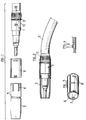
- the lance described in the figures comprises a lance body 1 which, at one of its ends, on the right in FIGS. 1 and 2, is connected to a supply duct 2, through which the gas intended to form the atmosphere passes. protective, as well as the wire electrode (not shown).
- the body 1 is of a conventional type, well known to those skilled in the art, and will not be described in more detail, except as regards the elements which are directly related to the present invention.
- a typically cylindrical-conical nozzle 3 is mounted on the body 1, the rear zone of which, intended to come into contact with the body, has longitudinal slots 4, intended to ensure elastic contact with the surface of the body.
- the nozzle In front of the slots 4, going towards the direction opposite to the supply duct 2, the nozzle externally has a circular groove 5, the utility of which will be explained below.
- a retaining spring 6 is provided, described in particular in FIG. 3, which is a flat spring rolled with a cylindrical shape, surrounding the nozzle over a little less than 360 ° and consequently constituting a split cylinder, the peripheral ends of which are separated by a longitudinal slot.
- the cylinder 6 has, towards one of its ends, two bosses 7, diametrically opposite, directed radially inwards, and delimited axially by two substantially radial faces.
- the cylinder has, towards its opposite end, two other bosses 8 facing each other, which are similar to the bosses 7.
- the shape of the bosses 7 is such that they can penetrate practically without play in the groove 5, which is of substantially square or rectangular cross section.
- the inside diameter of the spring 6 is slightly less than the outside diameter of the nozzle 3 in the region which contains the groove 5.
- the force of the spring 6 is calculated so that this spring can be pushed until the bosses 7 fall into the groove 5 , so as to ensure a good connection, without play, between the nozzle 3 and the spring 6.
- the body 1 has, in the vicinity of its connection with the supply duct 2, an outer circular rib 9, with substantially edges radial.
- This rib 9 is placed so as to constitute a stop defining the desired position for the nozzle 3.
- the rib 9 is interrupted by two notches 10, diametrically opposite, with a bottom parallel to the axis of the body, through which the bosses 8 of the spring retaining 6 can pass to go beyond the rib 9, going towards the supply duct.
- the distance between the lugs 7 and 8 of the spring is calculated so that, when the lugs 7 are in the groove 5, and the nozzle 3 is in its normal mounting position, that is to say in abutment against the rib 9 , the distance between the pins 7 and the pins 8 is very slightly less than the distance between the groove 5 and the face of the rib 9 which is turned towards the supply duct, so that, after having passes the pins 8 through the passages 10, and rotates the spring 6 around the body axis, the friction between the pins 8 and the rear face of the rib 9 is sufficient to prevent movement of the spring 6 relative to the body 1. It is possible to increase the effect of this friction by providing suitable reliefs on the face of the rib 9, such as notches cooperating with the edges of the lug 8.
- the spring 6 is first mounted on the nozzle 3, and the assembly formed by the spring and the nozzle is then rotated around the axis of the body to bring the lugs 8 into the desired position.
- FIG 4 shows a variant in which each of the notches 10 has a ramp 11 whose surface deviates radially from that of the body 1 in the direction of the supply duct 2.
- the role of these ramps is to cooperate with the bosses 8 of the retaining spring 6, so as to allow them to pass through the groove 9 when the spring is pushed in the direction of the connection with the supply duct 2, to fall back beyond this groove.
- the spring is mounted as soon as the pins 8 have crossed the ramps 11, if the pins have been placed beforehand in the groove 5. As a precaution, it is however advisable to rotate the spring with or without the nozzle, by an angle a few tens of degrees from the position corresponding to its positioning, so that the lugs 8 are not likely to tire the metal in the vicinity of the ramp 11.
- bosses 7 and 8 can be replaced by added projections, fixed to the inner face of the retaining spring 6 by suitable means.
- the number, shape and position of these bosses may also differ from the embodiment described, provided that the groove 5, the rib 9 and the ramps 11 have corresponding shapes.
Landscapes
- Engineering & Computer Science (AREA)
- Physics & Mathematics (AREA)
- Plasma & Fusion (AREA)
- Mechanical Engineering (AREA)
- Arc Welding In General (AREA)
- Gas Burners (AREA)
- Nozzles (AREA)
- Surgical Instruments (AREA)
Applications Claiming Priority (2)
| Application Number | Priority Date | Filing Date | Title |
|---|---|---|---|
| FR9412343A FR2725648B1 (fr) | 1994-10-17 | 1994-10-17 | Lance pour soudage electrique sous atmosphere protectrice |
| FR9412343 | 1994-10-17 |
Publications (2)
| Publication Number | Publication Date |
|---|---|
| EP0707918A1 true EP0707918A1 (de) | 1996-04-24 |
| EP0707918B1 EP0707918B1 (de) | 1997-12-03 |
Family
ID=9467909
Family Applications (1)
| Application Number | Title | Priority Date | Filing Date |
|---|---|---|---|
| EP19950402293 Expired - Lifetime EP0707918B1 (de) | 1994-10-17 | 1995-10-13 | Brenner zum elektrischen Schutzgasschweissen |
Country Status (4)
| Country | Link |
|---|---|
| EP (1) | EP0707918B1 (de) |
| DE (1) | DE69501142T2 (de) |
| ES (1) | ES2112616T3 (de) |
| FR (1) | FR2725648B1 (de) |
Cited By (1)
| Publication number | Priority date | Publication date | Assignee | Title |
|---|---|---|---|---|
| CN114269506A (zh) * | 2019-08-05 | 2022-04-01 | J·罗杰斯 | 具有可调电极接收器的惰性气体焊炬头 |
Families Citing this family (1)
| Publication number | Priority date | Publication date | Assignee | Title |
|---|---|---|---|---|
| CN105328371B (zh) * | 2014-08-06 | 2017-03-01 | 常州市维益科技有限公司 | 分段式焊枪电极夹 |
Citations (7)
| Publication number | Priority date | Publication date | Assignee | Title |
|---|---|---|---|---|
| DE2645679A1 (de) * | 1976-10-09 | 1978-04-13 | Binzel Alexander Gmbh Co Kg | Verbesserter schutzgasgekuehlter schutzgasschweissbrenner fuer das schweissen mit unendlicher elektrode |
| EP0003780A1 (de) * | 1978-02-23 | 1979-09-05 | Messer Griesheim Gmbh | Schutzgasschweissbrenner zum Lichtbogenschweissen mit abschmelzender Elektrode |
| DE8519433U1 (de) * | 1985-07-04 | 1985-09-05 | Carl Cloos Schweißtechnik GmbH, 6342 Haiger | Gasdüse für Schweißpistolen |
| US4554432A (en) * | 1984-10-05 | 1985-11-19 | Dover Corporation | Components for gas metal arc welding gun |
| DE3535357A1 (de) * | 1984-12-21 | 1986-07-03 | VEB Plastverarbeitung und Schweißtechnik Dresden, DDR 8028 Dresden | Gaskappe fuer schutzgasschweissbrenner |
| US4731518A (en) * | 1986-12-12 | 1988-03-15 | The Lincoln Electric Company | Gun and cable for gas metal arc welding |
| JPH06133779A (ja) * | 1992-10-27 | 1994-05-17 | Amano Pharmaceut Co Ltd | 新規dna化合物及びそれを用いて得られる組換体による3−メチル−7−アルキルキサンチンの製造法 |
-
1994
- 1994-10-17 FR FR9412343A patent/FR2725648B1/fr not_active Expired - Fee Related
-
1995
- 1995-10-13 EP EP19950402293 patent/EP0707918B1/de not_active Expired - Lifetime
- 1995-10-13 DE DE1995601142 patent/DE69501142T2/de not_active Expired - Fee Related
- 1995-10-13 ES ES95402293T patent/ES2112616T3/es not_active Expired - Lifetime
Patent Citations (7)
| Publication number | Priority date | Publication date | Assignee | Title |
|---|---|---|---|---|
| DE2645679A1 (de) * | 1976-10-09 | 1978-04-13 | Binzel Alexander Gmbh Co Kg | Verbesserter schutzgasgekuehlter schutzgasschweissbrenner fuer das schweissen mit unendlicher elektrode |
| EP0003780A1 (de) * | 1978-02-23 | 1979-09-05 | Messer Griesheim Gmbh | Schutzgasschweissbrenner zum Lichtbogenschweissen mit abschmelzender Elektrode |
| US4554432A (en) * | 1984-10-05 | 1985-11-19 | Dover Corporation | Components for gas metal arc welding gun |
| DE3535357A1 (de) * | 1984-12-21 | 1986-07-03 | VEB Plastverarbeitung und Schweißtechnik Dresden, DDR 8028 Dresden | Gaskappe fuer schutzgasschweissbrenner |
| DE8519433U1 (de) * | 1985-07-04 | 1985-09-05 | Carl Cloos Schweißtechnik GmbH, 6342 Haiger | Gasdüse für Schweißpistolen |
| US4731518A (en) * | 1986-12-12 | 1988-03-15 | The Lincoln Electric Company | Gun and cable for gas metal arc welding |
| JPH06133779A (ja) * | 1992-10-27 | 1994-05-17 | Amano Pharmaceut Co Ltd | 新規dna化合物及びそれを用いて得られる組換体による3−メチル−7−アルキルキサンチンの製造法 |
Non-Patent Citations (1)
| Title |
|---|
| PATENT ABSTRACTS OF JAPAN vol. 10, no. 189 (M - 494)<2245> 3 July 1986 (1986-07-03) * |
Cited By (1)
| Publication number | Priority date | Publication date | Assignee | Title |
|---|---|---|---|---|
| CN114269506A (zh) * | 2019-08-05 | 2022-04-01 | J·罗杰斯 | 具有可调电极接收器的惰性气体焊炬头 |
Also Published As
| Publication number | Publication date |
|---|---|
| EP0707918B1 (de) | 1997-12-03 |
| FR2725648B1 (fr) | 1997-01-10 |
| FR2725648A1 (fr) | 1996-04-19 |
| DE69501142D1 (de) | 1998-01-15 |
| DE69501142T2 (de) | 1998-07-02 |
| ES2112616T3 (es) | 1998-04-01 |
Similar Documents
| Publication | Publication Date | Title |
|---|---|---|
| FR2636395A1 (fr) | Assemblage a ecrous avec manchon rotatif pour reprendre le jeu | |
| EP1916182A1 (de) | Fahrrad-Steuerkopflager | |
| FR2711452A1 (fr) | Elément de connexion comportant un pontet isolant. | |
| EP1873804A2 (de) | Verfahren zur Befestigung eines Elements in einem elektrischen Gerät und elektrisches Gerät wie ein Vakuumrohr, das mindestens zwei Teile umfasst, die gemäß einem solchen Verfahren befestigt werden | |
| EP0026141A1 (de) | Sicherheits-Schraubverbindung | |
| EP0707918B1 (de) | Brenner zum elektrischen Schutzgasschweissen | |
| EP3572238B1 (de) | Nabe für ein fahrradrad | |
| EP0500410A1 (de) | Punktschweisszange | |
| EP1067356A1 (de) | Optischer Zünder mit einem Gradientenindex-Glasstab | |
| FR2713740A1 (fr) | Procédé de fixation d'une bague d'arrêt à un embout mâle d'un tuyau. | |
| EP0676024B1 (de) | Gasbrenndüse | |
| FR2675858A1 (fr) | Dispositif de fixation de bobines d'electrovannes. | |
| EP0842731A1 (de) | Verfahren und Vorrichtung zum Fixieren einer Gelenkstange, mit diesem Verfahren hergestelltes mehrgliedriges Armband | |
| FR2777341A1 (fr) | Dispositif de raccordement instantane pour tuyau | |
| EP0626533A1 (de) | Halteschelle auf einer Stütze für ein Rohr oder dergleichen | |
| FR2565141A1 (fr) | Dispositif pour le guidage et l'alimentation electrique d'un fil de metal d'apport pour le soudage a l'arc, et son procede de fabrication | |
| FR2998949A1 (fr) | Bougie de prechauffage de moteur diesel | |
| FR2539658A1 (fr) | Tube de guidage d'un fil de metal d'apport pour une installation de soudage par arc electrique | |
| EP0896850B1 (de) | Montagesystem für eine Elektrode in einem Schweissbrenner | |
| EP2381824B1 (de) | Verbinder für einen getränkezubereitungsautomat | |
| FR2734183A1 (fr) | Procede de fabrication d'un balancier de cornadis, le balancier de cornadis realise par le procede et un cornadis incorporant un tel balancier | |
| FR2746687A1 (fr) | Systeme de montage d'electrode dans une torche de soudage | |
| FR2535994A1 (fr) | Dispositif de maintien de boulons pour boulons a souder | |
| EP1695594A1 (de) | Elektrischer tauchheizer mit einem mantelheizelement | |
| FR2779244A1 (fr) | Procede d'assemblage d'une couronne de remontoir de montre sur une tige de remontoir |
Legal Events
| Date | Code | Title | Description |
|---|---|---|---|
| PUAI | Public reference made under article 153(3) epc to a published international application that has entered the european phase |
Free format text: ORIGINAL CODE: 0009012 |
|
| AK | Designated contracting states |
Kind code of ref document: A1 Designated state(s): BE CH DE ES GB IT LI |
|
| 17P | Request for examination filed |
Effective date: 19961024 |
|
| GRAG | Despatch of communication of intention to grant |
Free format text: ORIGINAL CODE: EPIDOS AGRA |
|
| GRAH | Despatch of communication of intention to grant a patent |
Free format text: ORIGINAL CODE: EPIDOS IGRA |
|
| 17Q | First examination report despatched |
Effective date: 19970317 |
|
| GRAH | Despatch of communication of intention to grant a patent |
Free format text: ORIGINAL CODE: EPIDOS IGRA |
|
| GRAA | (expected) grant |
Free format text: ORIGINAL CODE: 0009210 |
|
| AK | Designated contracting states |
Kind code of ref document: B1 Designated state(s): BE CH DE ES GB IT LI |
|
| REG | Reference to a national code |
Ref country code: CH Ref legal event code: EP |
|
| GBT | Gb: translation of ep patent filed (gb section 77(6)(a)/1977) |
Effective date: 19971209 |
|
| REF | Corresponds to: |
Ref document number: 69501142 Country of ref document: DE Date of ref document: 19980115 |
|
| ITF | It: translation for a ep patent filed | ||
| REG | Reference to a national code |
Ref country code: ES Ref legal event code: FG2A Ref document number: 2112616 Country of ref document: ES Kind code of ref document: T3 |
|
| PLBE | No opposition filed within time limit |
Free format text: ORIGINAL CODE: 0009261 |
|
| STAA | Information on the status of an ep patent application or granted ep patent |
Free format text: STATUS: NO OPPOSITION FILED WITHIN TIME LIMIT |
|
| 26N | No opposition filed | ||
| PG25 | Lapsed in a contracting state [announced via postgrant information from national office to epo] |
Ref country code: LI Free format text: LAPSE BECAUSE OF NON-PAYMENT OF DUE FEES Effective date: 19991031 Ref country code: CH Free format text: LAPSE BECAUSE OF NON-PAYMENT OF DUE FEES Effective date: 19991031 |
|
| REG | Reference to a national code |
Ref country code: CH Ref legal event code: PL |
|
| PGFP | Annual fee paid to national office [announced via postgrant information from national office to epo] |
Ref country code: GB Payment date: 20000919 Year of fee payment: 6 |
|
| PGFP | Annual fee paid to national office [announced via postgrant information from national office to epo] |
Ref country code: DE Payment date: 20000925 Year of fee payment: 6 |
|
| PGFP | Annual fee paid to national office [announced via postgrant information from national office to epo] |
Ref country code: ES Payment date: 20001010 Year of fee payment: 6 |
|
| PGFP | Annual fee paid to national office [announced via postgrant information from national office to epo] |
Ref country code: BE Payment date: 20001016 Year of fee payment: 6 |
|
| PG25 | Lapsed in a contracting state [announced via postgrant information from national office to epo] |
Ref country code: GB Free format text: LAPSE BECAUSE OF NON-PAYMENT OF DUE FEES Effective date: 20011013 |
|
| PG25 | Lapsed in a contracting state [announced via postgrant information from national office to epo] |
Ref country code: ES Free format text: LAPSE BECAUSE OF NON-PAYMENT OF DUE FEES Effective date: 20011014 |
|
| PG25 | Lapsed in a contracting state [announced via postgrant information from national office to epo] |
Ref country code: BE Free format text: LAPSE BECAUSE OF NON-PAYMENT OF DUE FEES Effective date: 20011031 |
|
| REG | Reference to a national code |
Ref country code: GB Ref legal event code: IF02 |
|
| BERE | Be: lapsed |
Owner name: SOUDURE AUTOGENE FRANCAISE Effective date: 20011031 |
|
| GBPC | Gb: european patent ceased through non-payment of renewal fee |
Effective date: 20011013 |
|
| PG25 | Lapsed in a contracting state [announced via postgrant information from national office to epo] |
Ref country code: DE Free format text: LAPSE BECAUSE OF NON-PAYMENT OF DUE FEES Effective date: 20020702 |
|
| REG | Reference to a national code |
Ref country code: ES Ref legal event code: FD2A Effective date: 20021113 |
|
| PG25 | Lapsed in a contracting state [announced via postgrant information from national office to epo] |
Ref country code: IT Free format text: LAPSE BECAUSE OF NON-PAYMENT OF DUE FEES Effective date: 20051013 |