EP0707929A1 - Verfahren zum Schneiden eines Stücks mit mindestens zwei übereinander angeordneten Schichten mit unterschiedlicher Härte; Eine von den Schichten hat eine grosse Elastizität - Google Patents
Verfahren zum Schneiden eines Stücks mit mindestens zwei übereinander angeordneten Schichten mit unterschiedlicher Härte; Eine von den Schichten hat eine grosse Elastizität Download PDFInfo
- Publication number
- EP0707929A1 EP0707929A1 EP95402319A EP95402319A EP0707929A1 EP 0707929 A1 EP0707929 A1 EP 0707929A1 EP 95402319 A EP95402319 A EP 95402319A EP 95402319 A EP95402319 A EP 95402319A EP 0707929 A1 EP0707929 A1 EP 0707929A1
- Authority
- EP
- European Patent Office
- Prior art keywords
- cutting
- cut
- layer
- tool
- hard material
- Prior art date
- Legal status (The legal status is an assumption and is not a legal conclusion. Google has not performed a legal analysis and makes no representation as to the accuracy of the status listed.)
- Withdrawn
Links
- 239000000463 material Substances 0.000 title claims abstract description 36
- 238000000034 method Methods 0.000 title claims abstract description 33
- 238000005520 cutting process Methods 0.000 title claims description 55
- 235000019589 hardness Nutrition 0.000 title claims description 13
- 229920001971 elastomer Polymers 0.000 claims abstract description 14
- 239000000806 elastomer Substances 0.000 claims abstract description 10
- 239000011248 coating agent Substances 0.000 claims description 18
- 238000000576 coating method Methods 0.000 claims description 18
- 238000005553 drilling Methods 0.000 claims description 6
- 238000012856 packing Methods 0.000 claims description 5
- 239000011159 matrix material Substances 0.000 claims description 2
- 239000007779 soft material Substances 0.000 claims 1
- 238000007493 shaping process Methods 0.000 description 10
- 229910000831 Steel Inorganic materials 0.000 description 8
- 239000010959 steel Substances 0.000 description 8
- 229910000838 Al alloy Inorganic materials 0.000 description 3
- 238000001125 extrusion Methods 0.000 description 2
- 238000003801 milling Methods 0.000 description 2
- 238000004080 punching Methods 0.000 description 2
- XAGFODPZIPBFFR-UHFFFAOYSA-N aluminium Chemical compound [Al] XAGFODPZIPBFFR-UHFFFAOYSA-N 0.000 description 1
- 229910052782 aluminium Inorganic materials 0.000 description 1
- 230000006835 compression Effects 0.000 description 1
- 238000007906 compression Methods 0.000 description 1
- 238000006073 displacement reaction Methods 0.000 description 1
- 239000013013 elastic material Substances 0.000 description 1
- 239000013536 elastomeric material Substances 0.000 description 1
- WABPQHHGFIMREM-UHFFFAOYSA-N lead(0) Chemical compound [Pb] WABPQHHGFIMREM-UHFFFAOYSA-N 0.000 description 1
- 238000003754 machining Methods 0.000 description 1
- 238000003032 molecular docking Methods 0.000 description 1
- 230000000149 penetrating effect Effects 0.000 description 1
- 230000035515 penetration Effects 0.000 description 1
- 230000002028 premature Effects 0.000 description 1
Images


Classifications
-
- B—PERFORMING OPERATIONS; TRANSPORTING
- B26—HAND CUTTING TOOLS; CUTTING; SEVERING
- B26D—CUTTING; DETAILS COMMON TO MACHINES FOR PERFORATING, PUNCHING, CUTTING-OUT, STAMPING-OUT OR SEVERING
- B26D7/00—Details of apparatus for cutting, cutting-out, stamping-out, punching, perforating, or severing by means other than cutting
- B26D7/08—Means for treating work or cutting member to facilitate cutting
- B26D7/084—Means for treating work or cutting member to facilitate cutting specially adapted for cutting articles composed of at least two different materials, e.g. using cutters of different shapes
Definitions
- the present invention relates to methods for making a cutting or shaping or the like in a part comprising at least two superimposed layers of materials of different hardnesses, one also having a high coefficient of elasticity.
- the object of the present invention is therefore to implement a process for cutting, shaping or the like in a part comprising at least two superimposed layers of materials of different hardnesses, one also having a high coefficient of elasticity, which overcomes the drawbacks of the previous methods mentioned above.
- the present invention relates to a method for making a cut in a part along a given cutting line, said part comprising at least two superimposed layers of materials of different hardnesses, one also having significant elasticity, in which said cutting is carried out by two successive cuts, characterized in that a first cut is made in at least the hardest layer before making the second cut in the elastic layer of the lowest hardness, to obtain the desired final cut .
- the method consists in carrying out the first cutting by pinching said part under a first pressure value and in carrying out the second cutting by subjecting said part to a second pressure value lower than said first value.
- the method consists in carrying out said first cutting along a cutting line situated very slightly back from said given cutting line, and in carrying out the second cutting along said given cutting line.
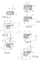
- Figures 1, 2 and 3 show schematically, respectively three stages of the implementation of the method according to the invention to achieve, by two successive cuts, a cut in a part 100 comprising, in the example illustrated, only two superposed layers 101 and 102 in materials of different hardnesses, one also having a high coefficient of elasticity.
- the layer 101 is made of a material which has a high coefficient of elasticity, for example an elastomer, rubber, etc.
- the layer 102 is made of a hard material whose elasticity is negligible, for example steel, aluminum, etc.
- this part 100 it is for example necessary to make a cut along a line, or plan, of given cut 103 as illustrated in dotted lines in FIG. 1. To do this, the part 100 is first kept clamped between the two jaws 104 and 105 of pliers or the like, in order to be able to carry out the first step of the process which consists in cutting the hardest layer 102 with a suitable tool, for example a milling cutter, to obtain a first cut like that which is represented in 106 in FIGS. 2 (in point-lines before its completion) and 3 (after its completion).
- a suitable tool for example a milling cutter
- the pressure exerted by the jaws 104 and 105 on the part is sufficient to keep it perfectly stable, but however causes a significant compression deformation of the part of the layer 101 in contact with one 104 of these jaws, as visible on the figure 2.
- the first cutting 106 is carried out entirely in the layer 102 and, possibly, partly in the part of the layer 101 which is in contact with the layer 102. If the cutting along the given cutting line 103 must be made perfectly clean in the elastic layer 101, the first cutting 106 in the layer 102 is advantageously made so that its plane 115 is very slightly set back from the theoretical cutting plane 103, for the purpose explained below.
- the part 100 having undergone the first cut 106 in the hard layer 102 is positioned between the two jaws 107 and 108 so that the edge 109 of the jaw 107 which is in contact with the elastic layer 101 is located as close as possible to the plane theoretical cutting 103. In this position, the elastic layer 101 is not compressed and it is possible to perform a second cutting to finish cutting the part 100 as desired, for example by means of the very sharp blade 110 by example of a circular knife.
- the blade 110 follows the theoretical cutting line 103 by penetrating into the material of the elastic layer 101 until it reaches the first cutting 106.
- the wire 111 of the blade 110 does not run the risk of being damaged in contact with the hard layer 102.
- This method is advantageous, in particular for defining, essentially in the elastic layer 101, a clear cutting surface 114 which is perfectly defined with respect to the surface 112 of this elastic layer which is not in contact with the hardest layer 102.
- This cutting surface 114 is of very good quality because it was made of an elastic material which was not deformed or compressed and the offset between the cutting plane 115 in the hard layer 102 and that of the cut 114 in the layer elastic 101 is very weak and negligible.
- FIG. 4 shows a first example of application of the implementation of the method, to the cutting of a rod 1 emerging, for example from extrusion, by forming a reinforced profile made up of a core 2 of hard material, by example of steel or the like, and of a flexible coating 3 made of elastomeric material or the like.
- Figure 6 shows the last phase of shaping to obtain the desired cut.
- the first tool removed the rod remains in place on its support 5 but the retaining flange 6 is loose.
- a blade 7 slides, in the opposite direction to that of the displacement of the tool 4, along a guide 8. This blade comes to cut the remaining elastomeric strip, above the notch.
- This blade is sharpened to perfectly cut flexible materials and, as the remaining elastomeric band is decompressed, the cut is perfectly clean and the surface condition of the notch is very good.
- the profile 1 is reinforced with two different materials, on the one hand a steel core 2 and on the other hand a rod 9 made of a material which can be softer than that of the core 2, for example made of aluminum alloy, the whole being embedded in an elastomeric coating 3.
- a steel core 2 and on the other hand a rod 9 made of a material which can be softer than that of the core 2, for example made of aluminum alloy, the whole being embedded in an elastomeric coating 3.
- an appropriate tool is used to ensure each cutting.
- a first tool 10 ensures for example a notch in the rod 9, without reaching the core 2 as shown in Figure 8.
- a second tool 4 capable of attacking the steel is used for cutting the core 2, without cutting all of the upper layer of the elastomeric coating 3.
- FIG. 10 illustrates the last step which is the cutting of this upper layer. This cut is obtained using for example a blade 7 similar to that which is illustrated in FIG. 6 and which moves in the opposite direction to the movement of the tools 10 and 4, the profile being simply supported on a bezel 5 appropriate.
- the method according to the invention also applies to punching or drilling, for example, of a bilayer part 11 as shown in FIG. 11, composed for example of a base or layer 12 of steel bearing a flexible coating or layer elastic 13.
- a drilling tool 14 suitable for the hardness of the steel ensures, from below, the drilling of the base 12 (fig. 12). Then, the part 11 is placed on a support 15, a matrix 16 is engaged in the hole made on the base and a punch 17 sliding in the opposite direction in a guide 18 can pierce the coating 13 in line with the hole (fig. 13) .
- the invention finds a particularly advantageous application for the cutting of a trim part of a motor vehicle, that is to say a rubber band armed with a rod or a semi-rigid aluminum alloy insert. or the like.
- This type of part constitutes, for example, a trim seal for a vehicle door and therefore requires quality cutting for the most perfect possible docking on the bodywork.
- FIG. 14 shows a U-shaped packing clip 19 in which an aluminum alloy core 9 is wrapped in an elastomer coating 3, a longitudinal lip 20 also in elastomer developing on one side of the clip.
- FIG. 15 illustrates the first step in the implementation of the method for cutting this longitudinal clamp 19, for example over part of its length or at its end.
- This first step consists in operating a tool 10 specific for cutting the core 9, in order to cut this core and the lower layer of the coating 3 in the bottom of the U, the penetration stroke of the tool 10 being limited so as to penetrate only very slightly into the upper layer of the coating 3.
- the last shaping step illustrated in FIG. 16 consists in making a cutting blade 7 suitable for the material of the coating 3 act to cut the upper layer of the coating.
- the cut of the upper layer of the coating material of the packing clamp, or seal, 19 is therefore perfectly straight and, if the cut in the rubber part located in the hollow of the seal is less clear because it has been obtained with a tool 10 not adapted to the nature of this material, this is immaterial since the pliers are intended to cover a bodywork element and this part is not visible.
Landscapes
- Life Sciences & Earth Sciences (AREA)
- Forests & Forestry (AREA)
- Engineering & Computer Science (AREA)
- Mechanical Engineering (AREA)
- Perforating, Stamping-Out Or Severing By Means Other Than Cutting (AREA)
Applications Claiming Priority (2)
| Application Number | Priority Date | Filing Date | Title |
|---|---|---|---|
| FR9412622A FR2725930B1 (fr) | 1994-10-21 | 1994-10-21 | Procede de faconnage de materiaux composites a l'aide de plusieurs outils |
| FR9412622 | 1994-10-21 |
Publications (1)
| Publication Number | Publication Date |
|---|---|
| EP0707929A1 true EP0707929A1 (de) | 1996-04-24 |
Family
ID=9468092
Family Applications (1)
| Application Number | Title | Priority Date | Filing Date |
|---|---|---|---|
| EP95402319A Withdrawn EP0707929A1 (de) | 1994-10-21 | 1995-10-18 | Verfahren zum Schneiden eines Stücks mit mindestens zwei übereinander angeordneten Schichten mit unterschiedlicher Härte; Eine von den Schichten hat eine grosse Elastizität |
Country Status (2)
| Country | Link |
|---|---|
| EP (1) | EP0707929A1 (de) |
| FR (1) | FR2725930B1 (de) |
Citations (5)
| Publication number | Priority date | Publication date | Assignee | Title |
|---|---|---|---|---|
| DE2005308A1 (de) * | 1969-02-07 | 1970-09-03 | Vandervell Products Ltd., London | Verfahren und Vorrichtung zum Durchschneiden von Verbundmaterial, vorzugsweise in Form von Streifen oder Bändern |
| FR2493210A1 (fr) * | 1980-10-06 | 1982-05-07 | Ig Tech Res Inc | Procede et dispositif pour couper une structure complexe et allongee |
| WO1983000841A1 (en) * | 1981-08-28 | 1983-03-17 | Duffield, Dean, Walter | Method for severing laminates |
| DE3925472A1 (de) * | 1988-08-03 | 1990-02-08 | Sallmetall Bv | Verfahren und vorrichtung zum schneiden von sandwichpaneelen |
| GB2257086A (en) * | 1991-06-25 | 1993-01-06 | Kingspan Res & Dev Ltd | Manufacturing an insulated panel |
-
1994
- 1994-10-21 FR FR9412622A patent/FR2725930B1/fr not_active Expired - Fee Related
-
1995
- 1995-10-18 EP EP95402319A patent/EP0707929A1/de not_active Withdrawn
Patent Citations (5)
| Publication number | Priority date | Publication date | Assignee | Title |
|---|---|---|---|---|
| DE2005308A1 (de) * | 1969-02-07 | 1970-09-03 | Vandervell Products Ltd., London | Verfahren und Vorrichtung zum Durchschneiden von Verbundmaterial, vorzugsweise in Form von Streifen oder Bändern |
| FR2493210A1 (fr) * | 1980-10-06 | 1982-05-07 | Ig Tech Res Inc | Procede et dispositif pour couper une structure complexe et allongee |
| WO1983000841A1 (en) * | 1981-08-28 | 1983-03-17 | Duffield, Dean, Walter | Method for severing laminates |
| DE3925472A1 (de) * | 1988-08-03 | 1990-02-08 | Sallmetall Bv | Verfahren und vorrichtung zum schneiden von sandwichpaneelen |
| GB2257086A (en) * | 1991-06-25 | 1993-01-06 | Kingspan Res & Dev Ltd | Manufacturing an insulated panel |
Also Published As
| Publication number | Publication date |
|---|---|
| FR2725930B1 (fr) | 1996-12-20 |
| FR2725930A1 (fr) | 1996-04-26 |
Similar Documents
| Publication | Publication Date | Title |
|---|---|---|
| EP0894046B1 (de) | Verfahren zum herstellen eines fertigen bauteiles mit einem bereich der fähig ist ein durchgang zu bilden, fertiges bauteil und entsprechende einheit | |
| CA2968247A1 (fr) | Vitrage a joint profile, enjoliveur et noyau et procede de fabrication du vitrage | |
| EP0707929A1 (de) | Verfahren zum Schneiden eines Stücks mit mindestens zwei übereinander angeordneten Schichten mit unterschiedlicher Härte; Eine von den Schichten hat eine grosse Elastizität | |
| FR2934554A1 (fr) | Installation de pose manuelle d'un joint d'etancheite colle sur une porte de vehicule automobile et procede associe. | |
| EP1755802B1 (de) | Crimp-werkzeug und damit ausgestattete vorrichtung | |
| FR2781713A1 (fr) | Procede d'ancrage d'une masse de matiere thermoplastique et piece obtenue par mise en oeuvre de ce procede | |
| EP2480355B1 (de) | Klemmring und dessen herstellungsverfahren | |
| FR2711749A1 (fr) | Adhésif avec pellicule de protection pelable, produits comportant un tel adhésif et leur procédé de réalisation. | |
| EP4330026B1 (de) | Vorrichtung und verfahren zum schneiden eines zwischenprodukts aus kautschuk | |
| FR2882709A1 (fr) | Piece d'habillage ayant une peau de cuir, et son procede de fabrication | |
| EP0703116B1 (de) | Verfahren zur Herstellung eines mit metallischer Armatur ausgerüsteten, extrudierten Dichtungsprofils für Kraftfahrzeuge. | |
| FR2901583A1 (fr) | Procede pour la mise en place et le retrait d'un clip de fixation amovible | |
| EP0443278A1 (de) | Verfahren zum Herstellen einer metallischen Armatur für Profile in biegsamem synthetischem Material | |
| EP0827909B1 (de) | Werkzeug zum Spannen eines Bandes, insbesondere eines Kabelbandes | |
| FR2650648A1 (fr) | Procede de fabrication d'une armature metallique pour profiles en une matiere synthetique resiliente | |
| FR2908394A1 (fr) | Frette a verrouillage securise | |
| WO2006092501A1 (fr) | Piece d'habillage ayant une peau et un support, et son procede de fabrication | |
| FR2868725A1 (fr) | Procede de fabrication d'une lame tranchante | |
| FR2661972A1 (fr) | Armature pour profile utilisable, en particulier, dans l'industrie automobile. | |
| FR2713742A1 (fr) | Armature, profilé d'étanchéité, son procédé de réalisation et son dispositif de fabrication. | |
| FR3132193A1 (fr) | Dispositif de mise en portion de saucisses à déchirement réduit | |
| FR2674798A1 (fr) | Procede de fabrication d'un pare-soleil recouvert d'un revetement et muni d'un bras de support. | |
| FR2803946A1 (fr) | Procede de realisation industrielle d'une forme d'accrochage d'une resine plastique de moulage | |
| FR2711950A1 (fr) | Procédé de fabrication d'une coulisse de glace, notamment pour porte d'automobile, et coulisse ainsi obtenue. | |
| FR2885549A1 (fr) | Procede de fabrication d'un coussin comportant une decoupe, et dispositif pour la mise en oeuvre d'un tel procede |
Legal Events
| Date | Code | Title | Description |
|---|---|---|---|
| PUAI | Public reference made under article 153(3) epc to a published international application that has entered the european phase |
Free format text: ORIGINAL CODE: 0009012 |
|
| AK | Designated contracting states |
Kind code of ref document: A1 Designated state(s): DE ES FR GB IT |
|
| 17P | Request for examination filed |
Effective date: 19961001 |
|
| 17Q | First examination report despatched |
Effective date: 19980205 |
|
| STAA | Information on the status of an ep patent application or granted ep patent |
Free format text: STATUS: THE APPLICATION IS DEEMED TO BE WITHDRAWN |
|
| 18D | Application deemed to be withdrawn |
Effective date: 19980616 |