EP0707934A1 - Entlüftung von Formen - Google Patents
Entlüftung von Formen Download PDFInfo
- Publication number
- EP0707934A1 EP0707934A1 EP95115959A EP95115959A EP0707934A1 EP 0707934 A1 EP0707934 A1 EP 0707934A1 EP 95115959 A EP95115959 A EP 95115959A EP 95115959 A EP95115959 A EP 95115959A EP 0707934 A1 EP0707934 A1 EP 0707934A1
- Authority
- EP
- European Patent Office
- Prior art keywords
- insert
- mold
- bore
- wall
- molding
- Prior art date
- Legal status (The legal status is an assumption and is not a legal conclusion. Google has not performed a legal analysis and makes no representation as to the accuracy of the status listed.)
- Granted
Links
- 238000013022 venting Methods 0.000 title claims description 24
- 238000000465 moulding Methods 0.000 claims abstract description 41
- 239000000463 material Substances 0.000 claims abstract description 20
- 238000004519 manufacturing process Methods 0.000 claims description 4
- 238000004891 communication Methods 0.000 claims description 3
- 238000000034 method Methods 0.000 description 9
- 238000005553 drilling Methods 0.000 description 8
- 235000019589 hardness Nutrition 0.000 description 7
- 239000004033 plastic Substances 0.000 description 5
- 229920003023 plastic Polymers 0.000 description 5
- 238000012423 maintenance Methods 0.000 description 3
- 239000004696 Poly ether ether ketone Substances 0.000 description 2
- 238000003754 machining Methods 0.000 description 2
- 239000007769 metal material Substances 0.000 description 2
- 229920002530 polyetherether ketone Polymers 0.000 description 2
- 238000009418 renovation Methods 0.000 description 2
- 238000004073 vulcanization Methods 0.000 description 2
- 229920000049 Carbon (fiber) Polymers 0.000 description 1
- 238000007205 Parnes methylation reaction Methods 0.000 description 1
- 229910000831 Steel Inorganic materials 0.000 description 1
- 230000006978 adaptation Effects 0.000 description 1
- 229910052782 aluminium Inorganic materials 0.000 description 1
- XAGFODPZIPBFFR-UHFFFAOYSA-N aluminium Chemical compound [Al] XAGFODPZIPBFFR-UHFFFAOYSA-N 0.000 description 1
- 239000011324 bead Substances 0.000 description 1
- 239000004917 carbon fiber Substances 0.000 description 1
- 238000010276 construction Methods 0.000 description 1
- 238000005520 cutting process Methods 0.000 description 1
- 230000007547 defect Effects 0.000 description 1
- 238000013461 design Methods 0.000 description 1
- 238000002513 implantation Methods 0.000 description 1
- 229910052751 metal Inorganic materials 0.000 description 1
- 239000002184 metal Substances 0.000 description 1
- VNWKTOKETHGBQD-UHFFFAOYSA-N methane Chemical compound C VNWKTOKETHGBQD-UHFFFAOYSA-N 0.000 description 1
- 125000000843 phenylene group Chemical group C1(=C(C=CC=C1)*)* 0.000 description 1
- 229920001021 polysulfide Polymers 0.000 description 1
- 239000011148 porous material Substances 0.000 description 1
- 238000003825 pressing Methods 0.000 description 1
- 239000010959 steel Substances 0.000 description 1
Images

Classifications
-
- B—PERFORMING OPERATIONS; TRANSPORTING
- B29—WORKING OF PLASTICS; WORKING OF SUBSTANCES IN A PLASTIC STATE IN GENERAL
- B29C—SHAPING OR JOINING OF PLASTICS; SHAPING OF MATERIAL IN A PLASTIC STATE, NOT OTHERWISE PROVIDED FOR; AFTER-TREATMENT OF THE SHAPED PRODUCTS, e.g. REPAIRING
- B29C33/00—Moulds or cores; Details thereof or accessories therefor
- B29C33/10—Moulds or cores; Details thereof or accessories therefor with incorporated venting means
-
- B—PERFORMING OPERATIONS; TRANSPORTING
- B29—WORKING OF PLASTICS; WORKING OF SUBSTANCES IN A PLASTIC STATE IN GENERAL
- B29D—PRODUCING PARTICULAR ARTICLES FROM PLASTICS OR FROM SUBSTANCES IN A PLASTIC STATE
- B29D30/00—Producing pneumatic or solid tyres or parts thereof
- B29D30/06—Pneumatic tyres or parts thereof (e.g. produced by casting, moulding, compression moulding, injection moulding, centrifugal casting)
- B29D30/08—Building tyres
-
- B—PERFORMING OPERATIONS; TRANSPORTING
- B29—WORKING OF PLASTICS; WORKING OF SUBSTANCES IN A PLASTIC STATE IN GENERAL
- B29D—PRODUCING PARTICULAR ARTICLES FROM PLASTICS OR FROM SUBSTANCES IN A PLASTIC STATE
- B29D30/00—Producing pneumatic or solid tyres or parts thereof
- B29D30/06—Pneumatic tyres or parts thereof (e.g. produced by casting, moulding, compression moulding, injection moulding, centrifugal casting)
- B29D30/0601—Vulcanising tyres; Vulcanising presses for tyres
- B29D30/0606—Vulcanising moulds not integral with vulcanising presses
- B29D2030/0607—Constructional features of the moulds
- B29D2030/0617—Venting devices, e.g. vent plugs or inserts
-
- B—PERFORMING OPERATIONS; TRANSPORTING
- B29—WORKING OF PLASTICS; WORKING OF SUBSTANCES IN A PLASTIC STATE IN GENERAL
- B29L—INDEXING SCHEME ASSOCIATED WITH SUBCLASS B29C, RELATING TO PARTICULAR ARTICLES
- B29L2030/00—Pneumatic or solid tyres or parts thereof
-
- Y—GENERAL TAGGING OF NEW TECHNOLOGICAL DEVELOPMENTS; GENERAL TAGGING OF CROSS-SECTIONAL TECHNOLOGIES SPANNING OVER SEVERAL SECTIONS OF THE IPC; TECHNICAL SUBJECTS COVERED BY FORMER USPC CROSS-REFERENCE ART COLLECTIONS [XRACs] AND DIGESTS
- Y10—TECHNICAL SUBJECTS COVERED BY FORMER USPC
- Y10S—TECHNICAL SUBJECTS COVERED BY FORMER USPC CROSS-REFERENCE ART COLLECTIONS [XRACs] AND DIGESTS
- Y10S425/00—Plastic article or earthenware shaping or treating: apparatus
- Y10S425/812—Venting
Definitions
- the present invention relates to molds, in particular for molding tires, and in particular the venting techniques used in these molds, to allow air trapped between the mold and a raw tire blank to escape towards the outside. .
- Tire molds are often fitted with a number of vents arranged in convenient locations. These vents are for example most often small diameter holes connecting the interior cavity of the mold to the outside of the mold.
- vents are for example most often small diameter holes connecting the interior cavity of the mold to the outside of the mold.
- drills it is not possible to make drills of extremely small diameter, due to limitations inherent in machining techniques, it follows that the diameter of these holes is generally sufficient to allow the rubber to creep at least slightly at inside these holes when the tire is molded. This is why we see on the surface of many tires small strands of rubber protruding slightly from the outer surface.
- vents known in the prior art have many drawbacks. If some of them allow air to escape while effectively preventing the appearance of mold burrs on the vulcanized tire, in general their duration satisfactory operation remains very low. This makes it necessary to maintain the mold far too frequently. It must therefore be removed regularly from the vulcanization press, and immobilized for the time necessary for maintenance operations. In addition, it is not always possible to restore the venting capacity of these vents. they must therefore be replaced fairly regularly. This leads to increasing the industrial cost price of these venting techniques. In addition, in the case of valve type vents, the starting cost price of such vents is relatively high.
- venting With regard to the tread of the tires, different means of venting are used: implantation of vents as described above, making simple holes, or else we also know how to take advantage of the slots which exist between the different parts. of the mold (joint planes between parts), in order to conduct air from the inside of the mold cavity to the outside of the mold. If necessary, one judiciously chooses, in relation to the tread of the tire, the places where the joint planes will pass between the different parts of the mold so that, whenever possible, a slot is found where the mold has to be fanned.
- the invention provides a mold having a mold cavity limited by mold walls made of one or more materials, each mold wall having a sealed molding surface defining part of the shape of the external surface of the object to be molded. , characterized in that at least one wall comprises at least one hole extending from said surface through said wall to put the mold cavity into communication with the outside of said mold, said hole being closed by an insert having an entirely sealed end face, flush with said surface to constitute a part of the molding surface, said insert occupying exactly the entire surface of said bore in said molding surface.
- the present invention does not propose to make a shape vent very sophisticated, no more than it suggests making a vent with moving parts, or using porous materials.
- the clearance between the insert and the hole receiving it is theoretically zero, it has been experimentally found that air can escape.
- the dimensioning of the proposed insert known as a venting device is extremely simple, the venting remains easy to carry out, even in a low-specialized workshop, such as in a tire production unit, in order to obtain venting gaps there. wherever you want.
- the hole appearing on the surface of the mold is of any shape.
- the easiest way is to make a circular drilling with a drill.
- a drilling diameter which proves to be interesting to adopt is between 2 and 3 mm.
- the trace of the insert appearing on the molding surface of the wall of the mold is less than a value of the order of 10 mm2. Preferably, this surface remains less than 100 mm2.
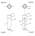
- the insert 1 according to the invention is presented as an elongated rod, having the appearance of a pin (see FIGS. 1 to 4).
- the insert has a lateral surface 10 and at least one end face 11 and an opposite end 12.
- the exact shape of this opposite end 12 is secondary: it can just as easily be a tapered point as a flat surface, known as shown in the drawings.
- Such inserts can be made very easily by molding a plastic material.
- the grooves 13, when they exist do not open onto the molding surface of the walls of the tire mold. They therefore do not open to the end surface 11.
- said lateral surface 10 which is at least in frustoconical parne, is such that the section of said insert 1 becomes narrower while moving towards the side where said grooves 13 open at said end opposite 12.
- the vent according to the invention is therefore a simple insert which will be mounted in a fitting hole on the known mold explained below.
- a tire mold namely a shell 2 intended to mold one of the sidewalls of the tire.
- the internal surface 20 of this shell 2 constitutes the exact image of the external surface of the sidewall of the tire which it is desired to mold.
- a hole such as 3 is drilled through this shell 2. It therefore makes it possible to put the interior cavity "I" of molding in communication with the exterior "E” of the mold.
- the hole 3 and the insert 1 are designed so as to present, for example, an H7 / m6 adjustment.
- the next step is to insert the insert 1 inside the hole 3, preferably from the side of the molding surface 20 (see Figures 5 and 6), until the side face 11 almost reaches the level of the molding surface 20 of the shell 2 (see FIG. 7).
- the insert 1 has grooves 13, it is necessary that the end 130 of these grooves is pressed inside the thickness of the shell 2, so that these grooves do not open at the level of the molding surface 20.
- the final step to construct a vent consists in leveling the insert 1 by means of a cutting tool in order to produce a molding surface 19 situated exactly and entirely in the extension of the molding surface 20 of the wall which surrounds the insert 1 (figure 8).
- the mold thus obtained therefore comprises an insert 1 made of a material whose hardness is much lower than the hardness of the material essentially constituting said wall 2, said insert 1 having before mounting a section circumscribed in the section of said bore 3 , at least on the side intended to be flush with said molding surface, said insert 1 being force-fitted into said bore 3.
- said end face 11 of said insert 1 possibly after leveling to constitute a molding surface 19 , is entirely in line with the molding surface 20 of the wall 2 bordering said bore 3.
- the vent proposed by the present invention has no moving parts. It does not call for any deformation or internal flexibility to allow the venting. If the materials used for this insert have a hardness very much lower than the hardness of the material constituting the mold, it is possible to use tight adjustments, without it being necessary to respect a narrow tolerance for the molding of the insert 1. It is possible to use plastics without undesirable influences being detected due to the lower thermal conductivity of the inserts compared to the molding wall.
- the state of vulcanization of the rubber molded by means of a mold thus equipped remains entirely comparable to that which occurs with molds equipped with metal vents or not equipped with a vent.
- the present invention used with other venting techniques at a higher flow rate, makes it possible to obtain the necessary venting in all the places of last molding having greater venting difficulty. It contributes to producing a mold allowing the molding of tires without defect in appearance. Its industrial operation is extremely reliable.
Landscapes
- Engineering & Computer Science (AREA)
- Mechanical Engineering (AREA)
- Moulds For Moulding Plastics Or The Like (AREA)
Applications Claiming Priority (2)
| Application Number | Priority Date | Filing Date | Title |
|---|---|---|---|
| FR9412654A FR2725933A1 (fr) | 1994-10-20 | 1994-10-20 | Eventation de moules |
| FR9412654 | 1994-10-20 |
Publications (2)
| Publication Number | Publication Date |
|---|---|
| EP0707934A1 true EP0707934A1 (de) | 1996-04-24 |
| EP0707934B1 EP0707934B1 (de) | 2000-01-05 |
Family
ID=9468117
Family Applications (1)
| Application Number | Title | Priority Date | Filing Date |
|---|---|---|---|
| EP95115959A Expired - Lifetime EP0707934B1 (de) | 1994-10-20 | 1995-10-10 | Entlüftung von Formen |
Country Status (9)
| Country | Link |
|---|---|
| US (1) | US6206336B1 (de) |
| EP (1) | EP0707934B1 (de) |
| JP (1) | JP3784867B2 (de) |
| KR (1) | KR100371043B1 (de) |
| BR (1) | BR9504485A (de) |
| CA (1) | CA2160954A1 (de) |
| DE (1) | DE69514308T2 (de) |
| ES (1) | ES2140604T3 (de) |
| FR (1) | FR2725933A1 (de) |
Cited By (2)
| Publication number | Priority date | Publication date | Assignee | Title |
|---|---|---|---|---|
| US5866171A (en) * | 1996-07-10 | 1999-02-02 | Bridgestone Corporation | Mold for tire vulcanization and manufacturing method thereof |
| US7731819B2 (en) | 2002-04-23 | 2010-06-08 | Georgia - Pacific Consumer Products Lp | Method of making creped towel and tissue incorporating high yield fiber |
Families Citing this family (10)
| Publication number | Priority date | Publication date | Assignee | Title |
|---|---|---|---|---|
| KR100383726B1 (ko) * | 2000-11-23 | 2003-05-14 | 한국타이어 주식회사 | 타이어 가류금형의 벤트피스 |
| JP3699362B2 (ja) * | 2001-05-02 | 2005-09-28 | 住友ゴム工業株式会社 | タイヤ加硫金型、及びタイヤの製造方法 |
| WO2006019087A1 (ja) * | 2004-08-20 | 2006-02-23 | Bridgestone Corporation | タイヤ成型用加硫金型およびその製造方法 |
| US7530803B2 (en) * | 2007-05-08 | 2009-05-12 | Bridgestone Firestone North American Tire, Llc | Insert for a tire mold vent |
| CN101821074B (zh) * | 2007-10-23 | 2014-03-19 | 倍耐力轮胎股份公司 | 用于硫化和模制轮胎的设备和方法 |
| JP5291976B2 (ja) * | 2008-04-21 | 2013-09-18 | 東洋ゴム工業株式会社 | タイヤ加硫金型用ベントプラグ、タイヤ加硫金型、及び該タイヤ加硫金型を使用した空気入りタイヤの製造方法 |
| US10020211B2 (en) * | 2014-06-12 | 2018-07-10 | Taiwan Semiconductor Manufacturing Company, Ltd. | Wafer-level molding chase design |
| CN113056378B (zh) * | 2018-11-19 | 2023-09-05 | 米其林集团总公司 | 集成式轮胎监测传感器容器 |
| JP7530377B2 (ja) * | 2019-02-19 | 2024-08-07 | プロプライアテクト・エル.ピー. | 複合発泡材物品 |
| CN110027138B (zh) * | 2019-06-12 | 2019-12-13 | 山东豪迈机械科技股份有限公司 | 排气装置及轮胎模具 |
Citations (9)
| Publication number | Priority date | Publication date | Assignee | Title |
|---|---|---|---|---|
| FR1394552A (fr) * | 1964-05-15 | 1965-04-02 | Firestone Tire & Rubber Co | Appareil de moulage |
| DE1965121A1 (de) * | 1969-12-27 | 1971-07-01 | Continental Gummi Werke Ag | Form,insbesondere Vulkanisierform mit Entlueftungsoeffnungen |
| US3822857A (en) * | 1971-02-16 | 1974-07-09 | Toyo Tire & Rubber Co | Synthetic resin plug for vent hole of mould |
| US3854852A (en) | 1973-01-12 | 1974-12-17 | Corn States Metal Fab Inc | Method and apparatus for forming a tire |
| US4447197A (en) | 1983-07-25 | 1984-05-08 | The B. F. Goodrich Company | Tire mold with air vent inserts |
| JPS61252109A (ja) * | 1985-05-02 | 1986-11-10 | Bridgestone Corp | 加硫用金型のベントプラグ |
| US4740145A (en) * | 1987-07-15 | 1988-04-26 | The Firestone Tire & Rubber Company | Flash-free vented tire mold |
| US5234326A (en) | 1990-04-13 | 1993-08-10 | Pirelli Coordinamento Pneumatici S.P.A. | Tire mold having a plurality of blocks defining a matrix with venting gaps between the blocks |
| EP0576892A1 (de) | 1992-07-02 | 1994-01-05 | Compagnie Generale Des Etablissements Michelin-Michelin & Cie | Reifenform, Verfahren zu deren Herstellung und Reifenformverfahren mit Hilfe einer solchen Form |
Family Cites Families (7)
| Publication number | Priority date | Publication date | Assignee | Title |
|---|---|---|---|---|
| FR394552A (de) | ||||
| US3474498A (en) | 1967-04-05 | 1969-10-28 | Nat Latex Products Co The | Interchangeable indicia-forming device for blow-molded plastic articles |
| US4492554A (en) * | 1980-08-26 | 1985-01-08 | Corn States Metal Fabricators, Inc. | Valve unit for a mold vent |
| US4347212A (en) * | 1980-08-26 | 1982-08-31 | Corn States Metal Fabricators, Inc. | Method for forming a tire |
| US4436497A (en) * | 1982-10-27 | 1984-03-13 | The Goodyear Tire & Rubber Company | Mold and vent plug therefor |
| US4795331A (en) * | 1986-09-15 | 1989-01-03 | The Goodyear Tire & Rubber Company | Mold vent plug |
| US5283022A (en) * | 1989-09-29 | 1994-02-01 | The Uniroyal Goodrich Tire Company | Restrictor for tire mold vent passage and method of use |
-
1994
- 1994-10-20 FR FR9412654A patent/FR2725933A1/fr not_active Withdrawn
-
1995
- 1995-10-10 ES ES95115959T patent/ES2140604T3/es not_active Expired - Lifetime
- 1995-10-10 EP EP95115959A patent/EP0707934B1/de not_active Expired - Lifetime
- 1995-10-10 DE DE69514308T patent/DE69514308T2/de not_active Expired - Lifetime
- 1995-10-11 US US08/540,947 patent/US6206336B1/en not_active Expired - Lifetime
- 1995-10-19 CA CA002160954A patent/CA2160954A1/fr not_active Abandoned
- 1995-10-20 BR BR9504485A patent/BR9504485A/pt not_active IP Right Cessation
- 1995-10-20 KR KR1019950036912A patent/KR100371043B1/ko not_active Expired - Lifetime
- 1995-10-20 JP JP27246595A patent/JP3784867B2/ja not_active Expired - Lifetime
Patent Citations (9)
| Publication number | Priority date | Publication date | Assignee | Title |
|---|---|---|---|---|
| FR1394552A (fr) * | 1964-05-15 | 1965-04-02 | Firestone Tire & Rubber Co | Appareil de moulage |
| DE1965121A1 (de) * | 1969-12-27 | 1971-07-01 | Continental Gummi Werke Ag | Form,insbesondere Vulkanisierform mit Entlueftungsoeffnungen |
| US3822857A (en) * | 1971-02-16 | 1974-07-09 | Toyo Tire & Rubber Co | Synthetic resin plug for vent hole of mould |
| US3854852A (en) | 1973-01-12 | 1974-12-17 | Corn States Metal Fab Inc | Method and apparatus for forming a tire |
| US4447197A (en) | 1983-07-25 | 1984-05-08 | The B. F. Goodrich Company | Tire mold with air vent inserts |
| JPS61252109A (ja) * | 1985-05-02 | 1986-11-10 | Bridgestone Corp | 加硫用金型のベントプラグ |
| US4740145A (en) * | 1987-07-15 | 1988-04-26 | The Firestone Tire & Rubber Company | Flash-free vented tire mold |
| US5234326A (en) | 1990-04-13 | 1993-08-10 | Pirelli Coordinamento Pneumatici S.P.A. | Tire mold having a plurality of blocks defining a matrix with venting gaps between the blocks |
| EP0576892A1 (de) | 1992-07-02 | 1994-01-05 | Compagnie Generale Des Etablissements Michelin-Michelin & Cie | Reifenform, Verfahren zu deren Herstellung und Reifenformverfahren mit Hilfe einer solchen Form |
Non-Patent Citations (1)
| Title |
|---|
| PATENT ABSTRACTS OF JAPAN vol. 011, no. 102 (M - 576) 31 March 1987 (1987-03-31) * |
Cited By (2)
| Publication number | Priority date | Publication date | Assignee | Title |
|---|---|---|---|---|
| US5866171A (en) * | 1996-07-10 | 1999-02-02 | Bridgestone Corporation | Mold for tire vulcanization and manufacturing method thereof |
| US7731819B2 (en) | 2002-04-23 | 2010-06-08 | Georgia - Pacific Consumer Products Lp | Method of making creped towel and tissue incorporating high yield fiber |
Also Published As
| Publication number | Publication date |
|---|---|
| FR2725933A1 (fr) | 1996-04-26 |
| DE69514308D1 (de) | 2000-02-10 |
| JP3784867B2 (ja) | 2006-06-14 |
| KR960013608A (ko) | 1996-05-22 |
| ES2140604T3 (es) | 2000-03-01 |
| DE69514308T2 (de) | 2000-05-25 |
| US6206336B1 (en) | 2001-03-27 |
| JPH08207049A (ja) | 1996-08-13 |
| CA2160954A1 (fr) | 1996-04-21 |
| KR100371043B1 (ko) | 2003-03-19 |
| BR9504485A (pt) | 1997-05-20 |
| EP0707934B1 (de) | 2000-01-05 |
Similar Documents
| Publication | Publication Date | Title |
|---|---|---|
| EP2379315B1 (de) | Auskleidungsanordnung auf einer haut einer reifenvulkanisierungsform | |
| EP2379317B1 (de) | Auskleidungsanordnung auf einer haut einer reifenvulkanisierungsform | |
| EP1232852B1 (de) | Formwerkzeug und Verfahren zum Formen einer Reifenlauffläche | |
| EP0707934B1 (de) | Entlüftung von Formen | |
| EP2384276B1 (de) | Eine anordnung aus nuten und kerben enthaltende reifenvulkanisierungsform | |
| EP0637504B1 (de) | Reifenform und Verfahren zum Formen von Reifen | |
| EP2909020B1 (de) | Formteil für eine reifenform mit porösem bereich | |
| FR2940166A1 (fr) | Procede de fabrication d'un element de garniture et d'un element de soutien destines a un moule de pneumatique | |
| EP0591745A2 (de) | Reifenform und Verfahren zum Formen von Reifen | |
| WO2014060207A1 (fr) | Element moulant d'un moule pour pneumatique comportant une pluralite de trous | |
| EP3242792B1 (de) | Matrixelement für reifenform und zugehöriges herstellungsverfahren | |
| EP2072287B1 (de) | Reifen, Form für die Vulkanisierung dieses Reifens, Herstellungsverfahren dieser Form und Matrize der Form | |
| EP0829658A1 (de) | Herstellungsverfahren eines Treibriemens und dadurch hergestellter Riemen | |
| EP2516181B1 (de) | Reifenprofil mit vertiefungen und einschnitten | |
| EP4021663A1 (de) | Verbessertes verfahren zur herstellung eines keramischen kerns zur herstellung von turbomaschinenschaufeln | |
| EP4117899A1 (de) | Auskleidungselement einer vulkanisierform für einen reifen mit lamellen | |
| EP4117898A1 (de) | Auskleidungselement für eine reifenvulkanisierform, die ein geeignetes formteil umfasst | |
| EP3787865B1 (de) | Formteil mit luftaustrittsschlitz und mikroformbereich | |
| EP3823804B1 (de) | Verfahren zur herstellung eines formelements mit einer entlüftungseinrichtung | |
| WO2004020168A2 (fr) | Procede de fabrication d’une piece en matiere plastique ayant un goulot muni d’un orifice de distribution destine a etre obture par un bouchon | |
| EP4076921A1 (de) | Vulkanisierform für reifen mit einer entlüftungsvorrichtung und verfahren zur vulkanisierung |
Legal Events
| Date | Code | Title | Description |
|---|---|---|---|
| PUAI | Public reference made under article 153(3) epc to a published international application that has entered the european phase |
Free format text: ORIGINAL CODE: 0009012 |
|
| AK | Designated contracting states |
Kind code of ref document: A1 Designated state(s): BE DE ES FR GB IT LU |
|
| 17P | Request for examination filed |
Effective date: 19961024 |
|
| 17Q | First examination report despatched |
Effective date: 19980427 |
|
| GRAG | Despatch of communication of intention to grant |
Free format text: ORIGINAL CODE: EPIDOS AGRA |
|
| GRAG | Despatch of communication of intention to grant |
Free format text: ORIGINAL CODE: EPIDOS AGRA |
|
| GRAH | Despatch of communication of intention to grant a patent |
Free format text: ORIGINAL CODE: EPIDOS IGRA |
|
| GRAH | Despatch of communication of intention to grant a patent |
Free format text: ORIGINAL CODE: EPIDOS IGRA |
|
| GRAA | (expected) grant |
Free format text: ORIGINAL CODE: 0009210 |
|
| AK | Designated contracting states |
Kind code of ref document: B1 Designated state(s): BE DE ES FR GB IT LU |
|
| RIN1 | Information on inventor provided before grant (corrected) |
Inventor name: REY, MAURICE Inventor name: LABARRE, DANIEL Inventor name: ESPIE, JACQUES |
|
| REF | Corresponds to: |
Ref document number: 69514308 Country of ref document: DE Date of ref document: 20000210 |
|
| REG | Reference to a national code |
Ref country code: ES Ref legal event code: FG2A Ref document number: 2140604 Country of ref document: ES Kind code of ref document: T3 |
|
| ITF | It: translation for a ep patent filed | ||
| GBT | Gb: translation of ep patent filed (gb section 77(6)(a)/1977) |
Effective date: 20000317 |
|
| PLBE | No opposition filed within time limit |
Free format text: ORIGINAL CODE: 0009261 |
|
| STAA | Information on the status of an ep patent application or granted ep patent |
Free format text: STATUS: NO OPPOSITION FILED WITHIN TIME LIMIT |
|
| 26N | No opposition filed | ||
| REG | Reference to a national code |
Ref country code: GB Ref legal event code: IF02 |
|
| PGFP | Annual fee paid to national office [announced via postgrant information from national office to epo] |
Ref country code: LU Payment date: 20071025 Year of fee payment: 13 Ref country code: ES Payment date: 20071030 Year of fee payment: 13 |
|
| PGFP | Annual fee paid to national office [announced via postgrant information from national office to epo] |
Ref country code: IT Payment date: 20071026 Year of fee payment: 13 |
|
| PGFP | Annual fee paid to national office [announced via postgrant information from national office to epo] |
Ref country code: BE Payment date: 20081120 Year of fee payment: 14 |
|
| PG25 | Lapsed in a contracting state [announced via postgrant information from national office to epo] |
Ref country code: IT Free format text: LAPSE BECAUSE OF NON-PAYMENT OF DUE FEES Effective date: 20081010 |
|
| REG | Reference to a national code |
Ref country code: ES Ref legal event code: FD2A Effective date: 20081011 |
|
| PG25 | Lapsed in a contracting state [announced via postgrant information from national office to epo] |
Ref country code: ES Free format text: LAPSE BECAUSE OF NON-PAYMENT OF DUE FEES Effective date: 20081011 |
|
| BERE | Be: lapsed |
Owner name: CIE GENERALE DES ETS *MICHELIN - MICHELIN & CIE Effective date: 20091031 |
|
| PG25 | Lapsed in a contracting state [announced via postgrant information from national office to epo] |
Ref country code: LU Free format text: LAPSE BECAUSE OF NON-PAYMENT OF DUE FEES Effective date: 20081010 |
|
| PG25 | Lapsed in a contracting state [announced via postgrant information from national office to epo] |
Ref country code: BE Free format text: LAPSE BECAUSE OF NON-PAYMENT OF DUE FEES Effective date: 20091031 |
|
| PGFP | Annual fee paid to national office [announced via postgrant information from national office to epo] |
Ref country code: FR Payment date: 20141022 Year of fee payment: 20 Ref country code: GB Payment date: 20141021 Year of fee payment: 20 Ref country code: DE Payment date: 20141022 Year of fee payment: 20 |
|
| REG | Reference to a national code |
Ref country code: DE Ref legal event code: R071 Ref document number: 69514308 Country of ref document: DE |
|
| REG | Reference to a national code |
Ref country code: GB Ref legal event code: PE20 Expiry date: 20151009 |
|
| PG25 | Lapsed in a contracting state [announced via postgrant information from national office to epo] |
Ref country code: GB Free format text: LAPSE BECAUSE OF EXPIRATION OF PROTECTION Effective date: 20151009 |