EP0708025A1 - Machine vertical à former, remplir et fermer des sachets - Google Patents
Machine vertical à former, remplir et fermer des sachets Download PDFInfo
- Publication number
- EP0708025A1 EP0708025A1 EP95113980A EP95113980A EP0708025A1 EP 0708025 A1 EP0708025 A1 EP 0708025A1 EP 95113980 A EP95113980 A EP 95113980A EP 95113980 A EP95113980 A EP 95113980A EP 0708025 A1 EP0708025 A1 EP 0708025A1
- Authority
- EP
- European Patent Office
- Prior art keywords
- welding
- film
- section
- packaging machine
- machine according
- Prior art date
- Legal status (The legal status is an assumption and is not a legal conclusion. Google has not performed a legal analysis and makes no representation as to the accuracy of the status listed.)
- Granted
Links
- 238000007789 sealing Methods 0.000 title description 3
- 238000004806 packaging method and process Methods 0.000 claims description 73
- 238000003466 welding Methods 0.000 claims description 73
- 239000000945 filler Substances 0.000 claims description 9
- 239000002985 plastic film Substances 0.000 claims description 6
- 229920006255 plastic film Polymers 0.000 claims description 6
- 238000010438 heat treatment Methods 0.000 claims description 3
- 239000000463 material Substances 0.000 claims 1
- 239000011888 foil Substances 0.000 abstract 2
- 238000012856 packing Methods 0.000 abstract 1
- 229920003023 plastic Polymers 0.000 abstract 1
- 239000004033 plastic Substances 0.000 abstract 1
- 238000013461 design Methods 0.000 description 5
- 238000004519 manufacturing process Methods 0.000 description 5
- 238000000465 moulding Methods 0.000 description 5
- 238000000605 extraction Methods 0.000 description 4
- 230000007704 transition Effects 0.000 description 4
- 239000002131 composite material Substances 0.000 description 2
- 238000003780 insertion Methods 0.000 description 2
- 230000037431 insertion Effects 0.000 description 2
- 239000007788 liquid Substances 0.000 description 2
- 238000000034 method Methods 0.000 description 2
- 235000011837 pasties Nutrition 0.000 description 2
- 238000007493 shaping process Methods 0.000 description 2
- 230000015572 biosynthetic process Effects 0.000 description 1
- 238000011161 development Methods 0.000 description 1
- 230000018109 developmental process Effects 0.000 description 1
- 230000002349 favourable effect Effects 0.000 description 1
- 238000005429 filling process Methods 0.000 description 1
- 239000008187 granular material Substances 0.000 description 1
- 238000002844 melting Methods 0.000 description 1
- 230000008018 melting Effects 0.000 description 1
- 238000012545 processing Methods 0.000 description 1
- 238000003860 storage Methods 0.000 description 1
- 239000000126 substance Substances 0.000 description 1
- 230000037303 wrinkles Effects 0.000 description 1
Images







Classifications
-
- B—PERFORMING OPERATIONS; TRANSPORTING
- B65—CONVEYING; PACKING; STORING; HANDLING THIN OR FILAMENTARY MATERIAL
- B65B—MACHINES, APPARATUS OR DEVICES FOR, OR METHODS OF, PACKAGING ARTICLES OR MATERIALS; UNPACKING
- B65B9/00—Enclosing successive articles, or quantities of material, e.g. liquids or semiliquids, in flat, folded, or tubular webs of flexible sheet material; Subdividing filled flexible tubes to form packages
- B65B9/10—Enclosing successive articles, or quantities of material, in preformed tubular webs, or in webs formed into tubes around filling nozzles, e.g. extruded tubular webs
- B65B9/20—Enclosing successive articles, or quantities of material, in preformed tubular webs, or in webs formed into tubes around filling nozzles, e.g. extruded tubular webs the webs being formed into tubes in situ around the filling nozzles
- B65B9/2042—Means for altering the cross-section of the tube filling opening prior to transversal sealing, e.g. tube spreading devices
-
- B—PERFORMING OPERATIONS; TRANSPORTING
- B65—CONVEYING; PACKING; STORING; HANDLING THIN OR FILAMENTARY MATERIAL
- B65B—MACHINES, APPARATUS OR DEVICES FOR, OR METHODS OF, PACKAGING ARTICLES OR MATERIALS; UNPACKING
- B65B9/00—Enclosing successive articles, or quantities of material, e.g. liquids or semiliquids, in flat, folded, or tubular webs of flexible sheet material; Subdividing filled flexible tubes to form packages
- B65B9/10—Enclosing successive articles, or quantities of material, in preformed tubular webs, or in webs formed into tubes around filling nozzles, e.g. extruded tubular webs
- B65B9/20—Enclosing successive articles, or quantities of material, in preformed tubular webs, or in webs formed into tubes around filling nozzles, e.g. extruded tubular webs the webs being formed into tubes in situ around the filling nozzles
Definitions
- the invention relates to a vertical tubular bag packaging machine with the features from the preamble of patent claim 1.
- tubular bag packaging machines are generally known.
- the principle of operation of a vertical tubular bag packaging machine is to produce and fill packaging bags fully automatically from a flat plastic film that is wound up as a roll. This means that the flat film is formed into a tube, its longitudinal edges being welded to one another and then welding seams being applied in the transverse direction, the packaging bag being filled with a product between the welding processes of the transverse seams.
- the invention has for its object to develop a tubular bag packaging machine of the type mentioned above so that a packaging bag made of plastic film for liquid, pasty and granular substances can be made on it and filled with the product, which has an essentially rectangular plan, with a front wall , a rear wall and two side walls and in each of which the vertical outer edges at the junctures between the walls of the packaging bag have welds which are designed such that the outer edges of the interconnected walls each point in the same direction to the outside.
- weld seams are also referred to as "fin seams". This configuration of the outer edge gives the packaging bag increased stability and, with an appropriate configuration of the bag base, increased stability.
- the bag can be manufactured using the tubular bag packaging machine in such a way that each side wall on the end facing the underside of the bag along its lower edge along one half of its width with the front wall and on the other half its width is connected to the rear wall by a weld.
- a suitable design of the tubular bag packaging machine this can be achieved, for example, by means of a composite plastic film which is composed of different plastic films and is heat sealable only on one side or at least has a lower melting point on one side than on the other side.
- a packaging bag for liquid, pasty and granular materials with the above-mentioned features, in which, when the bag is filled, lower sections of the film sections forming the side walls are folded inwards and completely folded under the bottom of the bag to form a flat contact surface and which has a considerable stability is described, for example, in European laid-open specification EP 0 580 989 A1.
- Packaging bags of this type have previously been produced as prefabricated bags. The filling took place in a completely separate operation and by means of a separate filling machine, which takes the prefabricated packaging bag from a magazine or the like.
- a packaging bag of the type mentioned above should be produced and filled by means of the tubular bag packaging machine according to the invention.
- the basic idea of the invention is to design a vertical tubular bag packaging machine in such a way that it is pulled off a roll
- a flat tubular film is formed in which the two longitudinal edges are not welded in the center of the bag as before and preferably so that no outwardly projecting seam occurs, but rather that a first weld seam in the area of one (front) corner edge of the bag is used as a fin seam is trained.
- the tubular film is then provided with a corresponding fin seam on the three remaining corner edges.
- the resulting film tube is welded in the transverse direction at the lower end that forms the bottom of the packaging bag, filled with the product through the filling tube, welded in the transverse direction on its upper side, separated and removed.
- the vertical tubular bag packaging machine according to the invention is for processing heat-sealable composite films of different thicknesses and for producing packaging bags with high stability with different sizes and suitable for filling them.
- FIGS. 2 to 20 a vertical tubular bag packaging machine of a known type is first explained and then the changes to such a machine according to FIGS. 2 to 20 are described.
- the tubular bag machine according to FIGS. 1A to 1C has a machine frame, generally designated 1, on which a holder 2 for receiving a roll of flat plastic film is arranged.
- a machine frame generally designated 1
- the flat film FF unwound from the roll is guided over various deflection rolls 3 of known design and arrangement to a shaped shoulder 4, by means of which it is pulled down and thereby formed into a tube which is pulled over a filling pipe 5 becomes.
- the hose is drawn off with pulling devices 6 of known design arranged on the side of the filling pipe 5.
- a welding device 7 of a known type is arranged in the center of the filling pipe 5 in the vertical direction, that is to say the longitudinal direction of the moving film, by means of which a longitudinal welding seam connecting the two opposite edges of the film is produced.
- the film is pulled down and passed through a welding device 8 to produce cross welds.
- the bags are filled after the application of a first transverse weld seam at the lower edge of the bag via the filling tube 5, and then closed on their upper side with a further transverse weld seam and removed or conveyed in a manner not specifically shown.
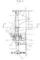
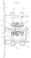
- the vertical tubular bag packaging machine which is now shown with reference to FIGS. 2 to 20, can correspond in its parts not shown in FIGS. 2 to 20 exactly to a tubular bag packaging machine of a known type, as was explained with reference to FIGS. 1A to 1C.
- a shaped shoulder 14 is also arranged in the upper part of the machine frame 11, through which a filling tube, generally designated 15, is passed in the vertical direction.
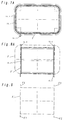
- the filling pipe 15 In a first inlet section 15.1 directly adjoining the shaped shoulder 14, the filling pipe 15 has a rectangular cross section, which can be seen in more detail in FIGS. 7 and 7A. This rectangular cross-section has rounded corners with a predetermined, relatively large radius.
- an outlet section 14.1 of the shaped shoulder 14 is formed which, as can also be seen from FIG. 7A, surrounds the inlet section 15.1 of the filling pipe 15.
- the film F is drawn into the space between the inlet section 15.1 of the filling tube 15 and the outlet section 14.1 of the shaped shoulder 14.
- the rounded corners of the cross sections of the filling tube and the shape shoulder at this point are necessary to ensure a smooth transition to ensure the flat film to form the tube without creating wrinkles or scoring on the shape shoulder.
- the shaped shoulder 14 itself is designed asymmetrically with a flat inlet angle such that the two longitudinal edges of the film lie asymmetrically to the vertical longitudinal center plane of the filling tube 15 and, as can be seen in FIG. 7A, are folded outward and opposite one another in a guide slot 14.2 on the tubular outlet section 14.1 of the shaped shoulder 14 are performed.
- the two outwardly facing and opposite edge regions of the film F are fed to a first welding device 17.1 for producing a longitudinal weld, the position of which can be seen in FIGS. 2 and 4 and which are located directly at the transition of the film from the inlet section 15.1 of the Filler tube 15 is arranged to form section 15.2.
- FIGS. 3 and 4 The arrangement and design of the shaped section 15.2 of the filling tube 15 can be seen in FIGS. 3 and 4 and, in particular, shown in more detail in FIGS.
- the shaped section 15.2 of the filling tube 15 also has a rectangular cross section, but with sharp corners and, as can be seen clearly from FIGS. 8 and 8A, are in the area of the front corner edge, which has not yet been assigned a longitudinal weld seam, and in the area of the two rear corner edges a predetermined length in the longitudinal direction, after corner lugs 15.3, 15.4, 15.5 projecting at the front or rear.
- the height of these corner lugs 15.3, 15.4 and 15.5 is dimensioned such that the outer circumference of the filler pipe 15 in the shaped section 15.2, including both sides of all three corner lugs, is equal to the circumference of the filler pipe 15 in the inlet section 15.1 (see FIGS. 7 and 7A).
- tubular film which is denoted by F in the inlet section 15.1 and has a rectangular cross section with rounded corners, can be drawn over the corner tabs 15.3, 15.4 and 15.5 in the shaped section 15.2 and thereby takes on a shape which is shown in FIG. 8A arranged in dash-dotted lines and labeled F 'and which is shown separately in FIG. 9.
- the film F is drawn over the corner lugs so that folds are produced in the film F 'above the corner lugs, which are formed in the manner described below by further welding devices for producing longitudinal weld seams into weld seams which, like the first longitudinal weld seam, form protruding edges or Fin seams are formed so that after passing through the shaped section 15.2 of the filling tube 15, the tubular film F ', which has the shape shown in FIG. 9, has four welding seams F1, F2, F3 and F4 projecting to the front and back.
- this first pressure plate is constructed in two parts, in that a second part 12.2, which lies opposite the corner nose 15.3, is arranged in segments in the main part 12, which simultaneously forms the counter bearing for the first welding device 17.1 and the side wall thereof, as can be seen in FIG. 4, the counter bearing is used for a second welding device 17.2 to produce a second longitudinal weld seam F2.
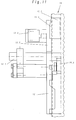
- the first pressure plate 12 is connected to a holder 12.1 and, as can be seen in FIG. 11, this is connected in a manner not specifically shown to a pneumatic cylinder arranged in the machine, by means of which the first pressure plate 12 is placed on the mold section 15.2 and lifted off it can.
- the segment-like part 12.2 can be created and lifted independently of this by means of a separate pneumatic drive 12.3 (see FIG. 11).
- this second pressure plate 13 On the back of the mold section 15.2 is one second pressure plate 13, which is also connected to a holder 13.1 and can be applied by means of a pneumatic drive, not shown, to the rear of the molded section 15.2 between the corner tabs 15.4 and 15.5.
- the side walls of this second pressure plate 13 also serve as counter bearings for a third welding device 17.3 and a fourth welding device 17.4 for producing the two longitudinal weld seams F3 and F4 (see FIG. 9).
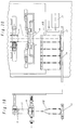
- FIG. 2 shows only the extraction device 16.1 arranged on the left side, while parts of the extraction device 16.2 arranged on the right side can be seen in FIG. 3, as well as a drive axle 16.3 common to the two extraction devices, which is not shown in FIG shown is driven from the inside of the machine. 2 shows the arrangements of the two extraction devices 16.1 and 16.2 in plan view.
- the welding devices 17.1, 17.2, 17.3 and 17.4 for producing the longitudinal welding seams F1, F2, F3 and F4 are on actuating devices 19.1, 19.2, 19.3 and 19.4 arranged, which are fastened to the machine frame 11 and can have, for example, pneumatic cylinders, by means of which the welding devices can be applied and lifted off. These independently operating actuators ensure that even if there are any deviations in the parallelism of the edges to be welded, a uniform pressure can be achieved on each of the longitudinal weld seams.
- Each of the welding devices is provided with its own temperature sensor and temperature controller, so that an exact temperature control is possible in the production of each of the longitudinal weld seams. As can be seen from FIG.
- the first welding device 17.1 is somewhat higher than the second welding device 17.2, at the level of which the welding devices 17.3 and 17.4 are also located. This ensures that the first longitudinal weld F1 is created in the first place and thus the tubular film is formed and then the further longitudinal welds F2, F3 and F4 are produced.
- the trigger devices 16.1 and 16.2 are also provided with devices for placing and lifting, not shown in detail. In Fig. 2 the left trigger device 16.1 is shown in dashed lines in the raised state. The withdrawal devices 16.1 and 16.2 are lifted off while the front and rear pressure plates 12 and 13 are being applied to the shaped section 15.2 of the filler pipe 15. In this way, the film F or F 'has the possibility of freely forming around the shaped section 15.2.
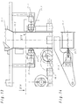
- the pressure plate 13 is guided on the one hand in a guide 13.1 and on the other hand connected to a drive shaft 13.2 which is guided through the front plate of the machine frame 11 to a pneumatic drive 13.3.
- a guide shoe 30.1 and 30.2 is arranged below the molding shoulder 14 on the left and right of the filling tube 15, which supports the transition of the film from the cross section of the inlet section 15.1 to the cross section of the molding section 15.2 in this area.
- a further welding device 18 for producing the welding seams running in the transverse direction is arranged below the lower end of the filling pipe 15 (FIGS. 2, 3 and 15 to 20).
- the film drawn off from the filling tube 15 as a tubular film is folded flat.
- the side walls of the tubular film must be folded in exactly in the middle.
- profile wheels 21.1 and 21.2 which are aligned with the center of the side walls and are pressed under pressure are arranged above the trigger devices 16.1 and 16.2.
- the profile wheels 21.1 and 21.2 engage in notches, not shown, on the shaped section 15.2 of the filling tube 15 and press the film into this notch. As a result, the Sidewall creates a center mark.
- the profile wheels 21.1 and 21.2 are connected to pneumatic cylinders 21.3 and 21.4 by means of corresponding brackets, so that they can optionally be lifted off and put back on again in order to enable the film to be aligned when the four longitudinal weld seams are formed.
- side wall folding slides 20.1 and 20.2 are arranged opposite the side walls, which can be moved inwards from actuating devices 20.3 and 20.4 and precisely on the Hit the middle of the side walls so that they are folded inwards.
- the actuators 20.3 and 20.4 are controlled centrally, so that it is ensured that a simultaneous insertion takes place on both sides and there is no distortion of the film in this area.
- a further pair of side wall folding slides 20.5 and 20.6 are arranged below the welding device 18, the movement of which is coupled with the movement of the first pair 20.1-20.2, so that a clean insertion of the film is ensured .
- the welding device 18 for producing the transverse weld seams is designed in the usual way with a welding plate 18.1 and a counter plate 18.2, which are arranged on mounting plates 25.1 and 25.2 (FIGS. 15 and 16), one mounting plate 25.2 being connected via mounting brackets 25.3 and the other mounting plate 25.1 via mounting brackets 25.4 each with actuating devices (not shown) for placing and lifting off, so that the two welding plates 18.1 and 18.2 are movable in opposite directions.
- the exact configuration of the sealing surfaces on the plate 18.1 can be seen in FIG. 17. It has two welding jaw parts 18.3 and 18.4 running parallel to one another in the transverse direction to produce the bottom seam of the subsequent packaging bag and the top seam of the preceding packaging bag. Furthermore, further partial jaws 18.5 and 18.6 are arranged at an angle of 45 ° to the welding jaw 18.3, with the aid of which additional welding seams can be produced in the bottom region of the packaging bag, each increasing at an angle of 45 ° to the side edges. This has favorable effects on the later stability of the filled packaging bag.
- the welding jaw 18.4 can also be designed to produce the upper cross weld so that a resealable bag is formed.
- the packaging bag can be removed directly after filling and closing.
- aids for forming the bag bottom are provided on the device described.
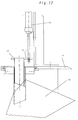
- These aids consist, on the one hand, of an inner tube 22 (see FIG. 12) which is displaceably guided within the filling tube 15 and is connected at its upper end via a holder 22.1 to an actuating device 23 designed as a pneumatic cylinder, by means of which it can be lowered and raised in cycles . It is advantageous if, as can be seen from FIGS. 3 and 19 and 20, the inner tube 22 can be lowered from the lower end of the filling tube 15 to the upper edge of the welding device 18.
- the inner tube 22 has at its lower end exactly the shape and cross section of the inner dimension of the packaging bag to be produced. This can be achieved, for example, by strips screwed on to the side on the lower edge of the inner tube 22.
- the bottom of the packaging bag is from molded inside.
- the inner tube 22 is raised so that the bag can be folded flat in the area of the welding device 18 by creating a wedge-shaped transition from the lower edge of the filling tube 15 to the welding device 18.
- two side wall expansion slides 26.1 and 26.2 are additionally actuated, which are arranged opposite the side walls of the packaging bag below the side wall folding slides 20.1 and 20.2 (see FIG. 18) and which are actuated by actuators 26.3 and 26.4 are cyclically movable towards and away from the side walls, this movement being coordinated with the up and down movement of the inner tube 22.
- These side wall expansion slides 26.1 and 26.2 bring the protruding longitudinal weld seams, which may have been partially set up laterally during cross-welding, back into the desired shape so that the bag bottom can be folded in exactly from the side.
- a device for receiving the filled packaging bags is arranged below the welding device 18 with a base plate 27 on which each filled packaging bag with its bag bottom is placed.
- the distance between the base plate 27 and the welding device 18 is greater than the height of the packaging bag, so that the bag can stand freely on the base plate 27.
- the filled and closed top and bottom packaging bags are separated by means of a separating knife 24 arranged in the usual manner in the welding device 18 for producing the transverse weld seams (FIG. 16).
- the packaging bag falls down and stands on the base plate 27, which is provided with a heating device.
- the heating of the base plate 27 ensures that the bottom shape of the packaging bag remains stable.
- Each finished packaging bag is pushed to the left in FIG. 20 by means of a laterally arranged push-off device 28, so that the packaging bags finally reach a storage plate 29 or a conveyor belt (not shown).
- Each work cycle is initiated so that the front pressure plate 12 is first pressed against the front of the molding section 15.2.
- This pressure plate 12 first fixes the film on the filling tube and serves as a counterbearing for the first welding device 17.1, which is arranged immediately after the inlet section 15.1 and has already been described, for producing the first longitudinal weld seam F1.
- the segment-like smaller part 12.2 of the front pressure plate is put on.
- the film is deflected via the front right corner nose 15.3 (FIG. 8A).
- the film makes a slight circular movement around the filling tube 15.
- the rear pressure plate 13 is applied.
- the film is guided over the rear corner lugs 15.4 and 15.5, so that the tubular film in cross-section receives the overall H-shaped shape shown in FIG. 9.
- the welding devices 17.2 to 17.4 are used to produce the three remaining longitudinal weld seams F2, F3 and F4 as fin seams.
- the film is folded in in the manner already described and fed to the welding device 18 to form the transverse weld seams.
- the inner tube 22 is lowered to unfold the bag bottom. Then the bag is filled and the inner tube 22 is raised again.
- the packaging bag is separated and discharged via the base plate 27 in the manner already described.
Landscapes
- Engineering & Computer Science (AREA)
- Mechanical Engineering (AREA)
- Containers And Plastic Fillers For Packaging (AREA)
- Supplying Of Containers To The Packaging Station (AREA)
Applications Claiming Priority (2)
| Application Number | Priority Date | Filing Date | Title |
|---|---|---|---|
| DE4431933A DE4431933A1 (de) | 1994-09-08 | 1994-09-08 | Vertikale Schlauchbeutelverpackungsmaschine |
| DE4431933 | 1994-09-08 |
Publications (2)
| Publication Number | Publication Date |
|---|---|
| EP0708025A1 true EP0708025A1 (fr) | 1996-04-24 |
| EP0708025B1 EP0708025B1 (fr) | 1998-07-15 |
Family
ID=6527671
Family Applications (1)
| Application Number | Title | Priority Date | Filing Date |
|---|---|---|---|
| EP95113980A Expired - Lifetime EP0708025B1 (fr) | 1994-09-08 | 1995-09-06 | Machine vertical à former, remplir et fermer des sachets |
Country Status (4)
| Country | Link |
|---|---|
| EP (1) | EP0708025B1 (fr) |
| AT (1) | ATE168341T1 (fr) |
| DE (2) | DE4431933A1 (fr) |
| ES (1) | ES2122415T3 (fr) |
Cited By (3)
| Publication number | Priority date | Publication date | Assignee | Title |
|---|---|---|---|---|
| US6615567B2 (en) * | 2000-04-07 | 2003-09-09 | Rovema Verpackungsmaschinen Gmbh | Vertical tubular bagging machine |
| NL1023151C2 (nl) * | 2003-01-06 | 2004-07-07 | C F S Weert B V | Inrichting en werkwijze voor het vervaardigen van hersluitbare verpakkingen. |
| NL1026499C2 (nl) * | 2003-01-06 | 2005-10-11 | Cfs Weert Bv | Inrichting en werkwijze voor het vervaardigen van hersluitbare verpakkingen. |
Families Citing this family (6)
| Publication number | Priority date | Publication date | Assignee | Title |
|---|---|---|---|---|
| DE19648406A1 (de) | 1996-11-22 | 1998-05-28 | Altamat Verpackungsmaschinen G | Vertikale Schlauchbeutelverpackungsmaschine |
| DE10039105A1 (de) * | 2000-08-07 | 2002-02-21 | Deltapack Verpackungsmaschinen | Verfahren zur Herstellung von Schlauchbeuteln aus Folien |
| DE10149476A1 (de) * | 2001-10-08 | 2003-04-17 | Rovema Gmbh | Schlauchbeutelmaschine zum Herstellen kantenverschweißter Schlauchbeutel |
| DE102006044914A1 (de) * | 2006-09-22 | 2008-04-03 | Rovema - Verpackungsmaschinen Gmbh | Schlauchbeutelmaschine mit einer kontinuierlich weiterbewegbaren Folienbahn |
| MX2017011162A (es) | 2015-03-18 | 2017-11-09 | Kellog Co | Bolsa erguida de fondo plano, sistema de llenado y sellado de modelo vertical y metodologia para utilizar el mismo. |
| WO2016207138A1 (fr) * | 2015-06-22 | 2016-12-29 | Nestec S.A. | Machine d'emballage |
Citations (4)
| Publication number | Priority date | Publication date | Assignee | Title |
|---|---|---|---|---|
| DE2657790A1 (de) * | 1976-12-21 | 1978-06-22 | Rovema Gmbh | Schlauchbeutelmaschine |
| US4117649A (en) * | 1976-03-29 | 1978-10-03 | Sig Schweizerische Industrie-Gesellschaft | System for forming, filling and closing bags |
| EP0029096A1 (fr) * | 1979-11-15 | 1981-05-27 | Tetra Laval Holdings & Finance SA | Dispositif et procédé pour la fabrication d'emballages remplis d'un produit liquide |
| EP0580989A1 (fr) * | 1992-06-04 | 1994-02-02 | Rodney Haydn Imer | Poche pour des matériaux liquides, pâteux ou granulaires et procédé de sa fabrication |
Family Cites Families (5)
| Publication number | Priority date | Publication date | Assignee | Title |
|---|---|---|---|---|
| DE1113174B (de) * | 1959-04-17 | 1961-08-24 | Hesser Ag Maschf | Vorrichtung zum Herstellen von Beutelpackungen |
| AT278660B (de) * | 1965-02-09 | 1970-02-10 | Hechenleitner & Cie | Maschine zum Herstellen und Füllen einer insbesondere zur Aufnahme von Flüssigkeiten geeigneten, quaderförmigen Packung |
| DE2337216A1 (de) * | 1973-07-21 | 1975-02-06 | Mira Pak Inc | Verfahren zur herstellung von beutelpackungen und vorrichtung zur durchfuehrung des verfahrens |
| CH608755A5 (fr) * | 1976-09-30 | 1979-01-31 | Sig Schweiz Industrieges | |
| DE3923713C2 (de) * | 1989-07-18 | 1993-12-23 | Kallfass Gmbh | Kunststoff-Schweißeinrichtung |
-
1994
- 1994-09-08 DE DE4431933A patent/DE4431933A1/de not_active Withdrawn
-
1995
- 1995-09-06 AT AT95113980T patent/ATE168341T1/de not_active IP Right Cessation
- 1995-09-06 ES ES95113980T patent/ES2122415T3/es not_active Expired - Lifetime
- 1995-09-06 DE DE59502815T patent/DE59502815D1/de not_active Expired - Fee Related
- 1995-09-06 EP EP95113980A patent/EP0708025B1/fr not_active Expired - Lifetime
Patent Citations (4)
| Publication number | Priority date | Publication date | Assignee | Title |
|---|---|---|---|---|
| US4117649A (en) * | 1976-03-29 | 1978-10-03 | Sig Schweizerische Industrie-Gesellschaft | System for forming, filling and closing bags |
| DE2657790A1 (de) * | 1976-12-21 | 1978-06-22 | Rovema Gmbh | Schlauchbeutelmaschine |
| EP0029096A1 (fr) * | 1979-11-15 | 1981-05-27 | Tetra Laval Holdings & Finance SA | Dispositif et procédé pour la fabrication d'emballages remplis d'un produit liquide |
| EP0580989A1 (fr) * | 1992-06-04 | 1994-02-02 | Rodney Haydn Imer | Poche pour des matériaux liquides, pâteux ou granulaires et procédé de sa fabrication |
Cited By (4)
| Publication number | Priority date | Publication date | Assignee | Title |
|---|---|---|---|---|
| US6615567B2 (en) * | 2000-04-07 | 2003-09-09 | Rovema Verpackungsmaschinen Gmbh | Vertical tubular bagging machine |
| NL1023151C2 (nl) * | 2003-01-06 | 2004-07-07 | C F S Weert B V | Inrichting en werkwijze voor het vervaardigen van hersluitbare verpakkingen. |
| EP1442980A1 (fr) * | 2003-01-06 | 2004-08-04 | CFS Weert B.V. | Appareil et procédé pour fabriquer des emballages refermables |
| NL1026499C2 (nl) * | 2003-01-06 | 2005-10-11 | Cfs Weert Bv | Inrichting en werkwijze voor het vervaardigen van hersluitbare verpakkingen. |
Also Published As
| Publication number | Publication date |
|---|---|
| ATE168341T1 (de) | 1998-08-15 |
| EP0708025B1 (fr) | 1998-07-15 |
| ES2122415T3 (es) | 1998-12-16 |
| DE59502815D1 (de) | 1998-08-20 |
| DE4431933A1 (de) | 1996-03-14 |
Similar Documents
| Publication | Publication Date | Title |
|---|---|---|
| DE2946059C2 (de) | Vorrichtung zum Herstellen mit Flüssigkeit gefüllter Packungen | |
| EP0781707B1 (fr) | Dispositif de scellement transversal pour une machine verticale de fabrication, de remplissage et de fermeture de sacs | |
| DE3140336C2 (de) | Packung für fließfähige Füllgüter und Vorrichtung zur Herstellung der Packung | |
| DE2904418A1 (de) | Behaelter aus duennem flexiblem kunststoff und verfahren zu deren herstellung | |
| EP1060072A1 (fr) | Dispositif de production des sacs fermes d'emballage | |
| DE2619437A1 (de) | Verfahren und vorrichtung zum verbinden einer folie mit mindestens einem eine verbindungsprofilleiste tragenden band, vorzugsweise zur herstellung von aus einer kunststoffolie gebildeten beuteln | |
| EP0708025B1 (fr) | Machine vertical à former, remplir et fermer des sachets | |
| EP0164079B1 (fr) | Machine pour produire des emballages contenant des solvants | |
| DE4122692B4 (de) | Vorrichtung zum Umhüllen quaderförmiger Gegenstände | |
| DE69400981T2 (de) | Standbeutel mit verbreiterter Standfläche | |
| DE3878275T2 (de) | Behaelter sowie verfahren und vorrichtung zu seiner herstellung. | |
| DE19539832B4 (de) | Verfahren und Vorrichtung zur Herstellung von Beuteln mit mindestens einem entlang einer Linie ausgedehnten Versteifungsbereich | |
| DE3614507A1 (de) | Verfahren und vorrichtung zum abpacken eines produktes in einzelne, vakuumdicht verschlossene packungen | |
| DE1486975B1 (de) | Verfahren und Vorrichtung zur Herstellung von mehrschichtigen Beuteln oder Saecken | |
| DE2720907A1 (de) | Tubenartiger behaelter und verfahren zum fuellen und zum herstellen eines tubenartigen behaelters | |
| DE1922826C3 (de) | Aus einem Schlauchabschnitt aus thermoplastischer Kunststoffolie hergestellter Sack mit einer Kreuzbodenfaltung sowie Verfahren und Vorrichtung zu seiner Herstellung | |
| DE102004006840A1 (de) | Verfahren und Maschine zur Herstellung wiederverschließbarer Beutel | |
| EP0315882A1 (fr) | Procédé pour l'emballage de marchandises dans des sachets d'emballage utilisant une feuille en forme de gaine ainsi que dispositif pour appliquer ce procédé | |
| DE1411557A1 (de) | Kubische Verpackung sowie Verfahren und Vorrichtung zu ihrer Herstellung | |
| DE3209971C2 (fr) | ||
| EP3452277B1 (fr) | Dispositif de transport et procédé de transport de sacs ou sachets ainsi que dispositif de fabrication de sacs ou sachets | |
| DE10027581A1 (de) | Schlauchbeutelmaschine zur Herstellung von Beuteln mit Kantensiegelung | |
| DE3740058C2 (fr) | ||
| DE3315487A1 (de) | Verfahren und vorrichtung zum herstellen einer kartonverpackung | |
| DE19901617C2 (de) | Schlauchbeutelmaschine |
Legal Events
| Date | Code | Title | Description |
|---|---|---|---|
| PUAI | Public reference made under article 153(3) epc to a published international application that has entered the european phase |
Free format text: ORIGINAL CODE: 0009012 |
|
| AK | Designated contracting states |
Kind code of ref document: A1 Designated state(s): AT BE CH DE DK ES FR GB IT LI NL PT SE |
|
| 17P | Request for examination filed |
Effective date: 19960917 |
|
| GRAG | Despatch of communication of intention to grant |
Free format text: ORIGINAL CODE: EPIDOS AGRA |
|
| 17Q | First examination report despatched |
Effective date: 19970902 |
|
| GRAG | Despatch of communication of intention to grant |
Free format text: ORIGINAL CODE: EPIDOS AGRA |
|
| GRAH | Despatch of communication of intention to grant a patent |
Free format text: ORIGINAL CODE: EPIDOS IGRA |
|
| GRAH | Despatch of communication of intention to grant a patent |
Free format text: ORIGINAL CODE: EPIDOS IGRA |
|
| GRAA | (expected) grant |
Free format text: ORIGINAL CODE: 0009210 |
|
| AK | Designated contracting states |
Kind code of ref document: B1 Designated state(s): AT BE CH DE DK ES FR GB IT LI NL PT SE |
|
| PG25 | Lapsed in a contracting state [announced via postgrant information from national office to epo] |
Ref country code: NL Free format text: LAPSE BECAUSE OF FAILURE TO SUBMIT A TRANSLATION OF THE DESCRIPTION OR TO PAY THE FEE WITHIN THE PRESCRIBED TIME-LIMIT Effective date: 19980715 Ref country code: IT Free format text: LAPSE BECAUSE OF FAILURE TO SUBMIT A TRANSLATION OF THE DESCRIPTION OR TO PAY THE FEE WITHIN THE PRE;WARNING: LAPSES OF ITALIAN PATENTS WITH EFFECTIVE DATE BEFORE 2007 MAY HAVE OCCURRED AT ANY TIME BEFORE 2007. THE CORRECT EFFECTIVE DATE MAY BE DIFFERENT FROM THE ONE RECORDED.SCRIBED TIME-LIMIT Effective date: 19980715 |
|
| REF | Corresponds to: |
Ref document number: 168341 Country of ref document: AT Date of ref document: 19980815 Kind code of ref document: T |
|
| REG | Reference to a national code |
Ref country code: CH Ref legal event code: EP |
|
| REF | Corresponds to: |
Ref document number: 59502815 Country of ref document: DE Date of ref document: 19980820 |
|
| PGFP | Annual fee paid to national office [announced via postgrant information from national office to epo] |
Ref country code: DE Payment date: 19980925 Year of fee payment: 4 |
|
| PGFP | Annual fee paid to national office [announced via postgrant information from national office to epo] |
Ref country code: FR Payment date: 19980929 Year of fee payment: 4 |
|
| PGFP | Annual fee paid to national office [announced via postgrant information from national office to epo] |
Ref country code: AT Payment date: 19980930 Year of fee payment: 4 |
|
| PG25 | Lapsed in a contracting state [announced via postgrant information from national office to epo] |
Ref country code: SE Free format text: LAPSE BECAUSE OF FAILURE TO SUBMIT A TRANSLATION OF THE DESCRIPTION OR TO PAY THE FEE WITHIN THE PRESCRIBED TIME-LIMIT Effective date: 19981015 Ref country code: PT Free format text: LAPSE BECAUSE OF FAILURE TO SUBMIT A TRANSLATION OF THE DESCRIPTION OR TO PAY THE FEE WITHIN THE PRESCRIBED TIME-LIMIT Effective date: 19981015 Ref country code: DK Free format text: LAPSE BECAUSE OF FAILURE TO SUBMIT A TRANSLATION OF THE DESCRIPTION OR TO PAY THE FEE WITHIN THE PRESCRIBED TIME-LIMIT Effective date: 19981015 |
|
| GBT | Gb: translation of ep patent filed (gb section 77(6)(a)/1977) |
Effective date: 19981015 |
|
| REG | Reference to a national code |
Ref country code: CH Ref legal event code: NV Representative=s name: A. BRAUN, BRAUN, HERITIER, ESCHMANN AG PATENTANWAE |
|
| ET | Fr: translation filed | ||
| NLV1 | Nl: lapsed or annulled due to failure to fulfill the requirements of art. 29p and 29m of the patents act | ||
| REG | Reference to a national code |
Ref country code: ES Ref legal event code: FG2A Ref document number: 2122415 Country of ref document: ES Kind code of ref document: T3 |
|
| PLBE | No opposition filed within time limit |
Free format text: ORIGINAL CODE: 0009261 |
|
| STAA | Information on the status of an ep patent application or granted ep patent |
Free format text: STATUS: NO OPPOSITION FILED WITHIN TIME LIMIT |
|
| 26N | No opposition filed | ||
| PG25 | Lapsed in a contracting state [announced via postgrant information from national office to epo] |
Ref country code: AT Free format text: LAPSE BECAUSE OF NON-PAYMENT OF DUE FEES Effective date: 19990906 |
|
| PGFP | Annual fee paid to national office [announced via postgrant information from national office to epo] |
Ref country code: GB Payment date: 19990908 Year of fee payment: 5 |
|
| PGFP | Annual fee paid to national office [announced via postgrant information from national office to epo] |
Ref country code: ES Payment date: 19990923 Year of fee payment: 5 |
|
| PG25 | Lapsed in a contracting state [announced via postgrant information from national office to epo] |
Ref country code: LI Free format text: LAPSE BECAUSE OF NON-PAYMENT OF DUE FEES Effective date: 19990930 Ref country code: CH Free format text: LAPSE BECAUSE OF NON-PAYMENT OF DUE FEES Effective date: 19990930 |
|
| PGFP | Annual fee paid to national office [announced via postgrant information from national office to epo] |
Ref country code: BE Payment date: 19991119 Year of fee payment: 5 |
|
| REG | Reference to a national code |
Ref country code: CH Ref legal event code: PL |
|
| PG25 | Lapsed in a contracting state [announced via postgrant information from national office to epo] |
Ref country code: FR Free format text: LAPSE BECAUSE OF NON-PAYMENT OF DUE FEES Effective date: 20000531 |
|
| PG25 | Lapsed in a contracting state [announced via postgrant information from national office to epo] |
Ref country code: DE Free format text: LAPSE BECAUSE OF NON-PAYMENT OF DUE FEES Effective date: 20000701 |
|
| REG | Reference to a national code |
Ref country code: FR Ref legal event code: ST |
|
| PG25 | Lapsed in a contracting state [announced via postgrant information from national office to epo] |
Ref country code: GB Free format text: LAPSE BECAUSE OF NON-PAYMENT OF DUE FEES Effective date: 20000906 |
|
| PG25 | Lapsed in a contracting state [announced via postgrant information from national office to epo] |
Ref country code: ES Free format text: LAPSE BECAUSE OF NON-PAYMENT OF DUE FEES Effective date: 20000907 |
|
| PG25 | Lapsed in a contracting state [announced via postgrant information from national office to epo] |
Ref country code: BE Free format text: LAPSE BECAUSE OF NON-PAYMENT OF DUE FEES Effective date: 20000930 |
|
| BERE | Be: lapsed |
Owner name: ALTAMAT VERPACKUNGSMASCHINEN G.M.B.H. Effective date: 20000930 |
|
| GBPC | Gb: european patent ceased through non-payment of renewal fee |
Effective date: 20000906 |
|
| REG | Reference to a national code |
Ref country code: ES Ref legal event code: FD2A Effective date: 20011011 |