EP0708047B1 - Verfahren und Vorrichtung zum Abwickeln einer Warenbahn - Google Patents
Verfahren und Vorrichtung zum Abwickeln einer Warenbahn Download PDFInfo
- Publication number
- EP0708047B1 EP0708047B1 EP95116030A EP95116030A EP0708047B1 EP 0708047 B1 EP0708047 B1 EP 0708047B1 EP 95116030 A EP95116030 A EP 95116030A EP 95116030 A EP95116030 A EP 95116030A EP 0708047 B1 EP0708047 B1 EP 0708047B1
- Authority
- EP
- European Patent Office
- Prior art keywords
- torque transmission
- transmission element
- winding
- reel
- clamping
- Prior art date
- Legal status (The legal status is an assumption and is not a legal conclusion. Google has not performed a legal analysis and makes no representation as to the accuracy of the status listed.)
- Expired - Lifetime
Links
- 238000000034 method Methods 0.000 title description 2
- 238000004804 winding Methods 0.000 claims description 73
- 230000005540 biological transmission Effects 0.000 claims description 19
- 230000008878 coupling Effects 0.000 claims description 7
- 238000010168 coupling process Methods 0.000 claims description 7
- 238000005859 coupling reaction Methods 0.000 claims description 7
- 239000000463 material Substances 0.000 description 5
- 238000006073 displacement reaction Methods 0.000 description 3
- 238000004519 manufacturing process Methods 0.000 description 2
- 230000001360 synchronised effect Effects 0.000 description 2
- 244000059549 Borneo rubber Species 0.000 description 1
- 210000001015 abdomen Anatomy 0.000 description 1
- 230000007423 decrease Effects 0.000 description 1
- 230000002093 peripheral effect Effects 0.000 description 1
- 229920002635 polyurethane Polymers 0.000 description 1
- 239000004814 polyurethane Substances 0.000 description 1
- 238000013022 venting Methods 0.000 description 1
Images

Classifications
-
- B—PERFORMING OPERATIONS; TRANSPORTING
- B65—CONVEYING; PACKING; STORING; HANDLING THIN OR FILAMENTARY MATERIAL
- B65H—HANDLING THIN OR FILAMENTARY MATERIAL, e.g. SHEETS, WEBS, CABLES
- B65H26/00—Warning or safety devices, e.g. automatic fault detectors, stop-motions, for web-advancing mechanisms
-
- B—PERFORMING OPERATIONS; TRANSPORTING
- B65—CONVEYING; PACKING; STORING; HANDLING THIN OR FILAMENTARY MATERIAL
- B65H—HANDLING THIN OR FILAMENTARY MATERIAL, e.g. SHEETS, WEBS, CABLES
- B65H16/00—Unwinding, paying-out webs
- B65H16/10—Arrangements for effecting positive rotation of web roll
-
- B—PERFORMING OPERATIONS; TRANSPORTING
- B65—CONVEYING; PACKING; STORING; HANDLING THIN OR FILAMENTARY MATERIAL
- B65H—HANDLING THIN OR FILAMENTARY MATERIAL, e.g. SHEETS, WEBS, CABLES
- B65H2301/00—Handling processes for sheets or webs
- B65H2301/40—Type of handling process
- B65H2301/41—Winding, unwinding
- B65H2301/414—Winding
- B65H2301/4146—Winding involving particular drive arrangement
- B65H2301/41464—Winding involving particular drive arrangement lateral drive arrangement, e.g. operating on the flange of the web roll
Definitions
- the invention relates to and a device for Unwinding a web, especially one Paper web, for example in a winding roll changer a rotary printing press according to the preamble of Claim 1.
- DE-A 42 34 344 discloses a device for Unwinding of a material web in a winding roll changer, the web on a winding core in the form of a Winding roll is wound and in ends of Expandable, rotatable cones for winding core Engage the take-up of the winding roll, the torques transfer the winding core and thus to the winding roll, and wherein at least one torque transmission element at times synchronous with the clamping cones is provided with an end face of the Coil on and coactively interacting is arranged adjustable, the Torque transmission element integral with the Clamping cone is arranged axially movable.
- This device is in one Production machine for changing rolls in web form Material used. This becomes a core of the role of spindles recorded and act on the end face of the roll a disc arranged suction cups. These suction cups or the disc is torsionally rigid with a spindle connected.
- a disadvantage of this device is that the edges of the Material web when the diameter falls below the Roll compared to a diameter of the disc can be damaged.
- US-A 38 51 834 describes a device for Unwinding a web, the web on a Winding core is wound in the form of a winding roll and wherein a rotatable chuck for receiving the winding roll protrudes through the winding core and Torques on the winding core and thus on the Transfers winding roll, and being at least one Torque transmission element temporarily synchronized with the clamping device is provided all around, with one end face of the winding roll frictionally is arranged interactively on and off, wherein the torque transmission element regardless of and axially movable coaxially with the clamping device is arranged.
- This device for light film rolls is not suitable for a relatively heavy winding roll in one Winding reel changer of a rotary printing machine.
- DE 35 21 582 C2 is a device for Clamping winding cores known in the rotatable Clamping cones with tubular segment-shaped clamping elements are provided. These tensioning elements expand and thus clamp the winding core on the tensioning cones.
- the disadvantage of this device is that the at today usual winding rolls with large diameters and large Large occurring moments of inertia Speed changes of the winding roll do not exceed the Clamping cones can be transferred.
- the invention has for its object a Device for unwinding a web of goods with temporary acting on an end face of a winding roll To create torque transmission elements at damage to the web is prevented, too if a diameter of the winding roll is smaller than one Diameter of the torque transmission elements is.
- the device according to the invention is in the drawing shown and is described in more detail below.
- a device for unwinding a material web 1, especially a paper web is for example in a winding reel changer of a rotary printing machine integrated.
- a shaft 4 is mounted in side frames 2, 3 of the winding roll changer of a rotary printing press, on which a right and left bearing arm 6, 7 are fastened. These bearing arms 6, 7 are axially displaceable on the shaft 4, but arranged in a rotationally fixed manner by a distance a, z. B. 2.5 m, the bearing arms of a width b, z. B. 2 m, the web 1, ie to adapt a winding roll 8 and to determine a position of the winding roll 8 with respect to a central axis 9 of the rotary printing press.
- the shaft 4 can be pivoted by means of drives (not shown) in order to bring the winding roll 8 into different positions required for changing the winding rolls.
- the left bearing arm 6 has a first bearing, for example in a bore 12 lying concentrically to an axis of rotation 11 of the winding roller 8.
- B. needle bearing 13 which receives a tubular hollow shaft 14 rotatable and axially displaceable.
- Actuating devices 16 act on this hollow shaft 14, which can move the hollow shaft 14 axially, even with simultaneous rotation of the hollow shaft 14.
- the end 17 of the hollow shaft 14 facing away from the winding roll 8 is provided with a circumferential annular collar 18 which is perpendicular to the axis of rotation 11 and which comprises a non-rotating forked ring 19 or one or more fork segments, as seen in section.
- Axial bearings can be arranged between the collar 18 and the fork-shaped ring 19, for example on both sides 21, 22 of the collar 18.
- a fork segment are formed such that cam rollers act on both sides of the collar, the bolts of which are connected in parallel via a coupling.
- One or more positioning drives are arranged parallel and concentric to the axis of rotation 11.
- single-acting, spring-loaded pneumatic cylinders 23 are used as positioning drives.
- Other known positioning drives such as e.g. As hydraulic cylinders, spindle drives, linear drives, etc.
- This disk 26 is provided on its two plane sides 27, 28 with friction linings 29, so that the friction linings 29 are connected to the hollow shaft 14 in a torsionally rigid manner.
- These friction linings 29 can be in the form of annular disks with an outer diameter d1, e.g. B. 700 mm, which are simply integrally connected to the disk 26 of the hollow shaft 14.
- d1 outer diameter
- d1 outer diameter
- the disc 26 of the hollow shaft 14 can also be used only as narrow disk can be executed, for example is connected to the hollow shaft 14 by means of spokes, or z. B. from individual provided with friction linings 29, plates attached to support arms.
- This Support arms can be designed such that they can be pivoted the plates on and off the end face of the winding roll can be switched off.
- a second storage for. B. needle bearing 31, which receives a shaft 32 concentrically rotatable about the axis of rotation 11 and axially displaceable.
- the shaft 32 is provided with an adjusting device 33, which can move the shaft 32 axially, even when the hollow shaft 14 rotates.
- This actuator 33 can adequately the actuator 16 of the hollow shaft 14, z. B. with pneumatic cylinders 34 to be executed.
- An end 36 of the shaft 32 facing away from the winding roll 8 is connected by means of a coupling 37 which transmits torques and at least compensates for axial displacement of the shaft 32, e.g. B. spline connection with a braking device 38, for. B. disc brake, with a drive 39, z. B. three-phase motor, and with a speed sensor 41, z. B. incremental encoder coupled.
- An end 42 of the shaft 32 facing the winding roll 8 is with a known cone 43 for Recording of a tubular winding core 44 of the Provide winding roll 8.
- This clamping cone 43 can for example pneumatically operated, expanding Have jaws.
- the hollow shaft 14 and the shaft 32 are by means of a switchable, torsionally rigid coupling 46 connected. in the present example is this clutch 46 as switchable spline connection.
- a yourself axially extending area of the shaft 32 is as Splined shaft 47 and profiled in the hollow shaft 14 Wedge hub 48 rigidly attached.
- the respective wedges 49 from Spline shaft 47 and spline hub 48 are at both ends 51, 52 tapering, e.g. B. in the axial direction arrow-shaped, formed. But z. Belly known, radially acting friction clutches used become.
- the right bearing arm 7 is a mirror image of the described left bearing arm 6. However, the drive 39 and the speed sensor 41 can be omitted here.
- a sensor 53 for. B. an optoelectric reflection button, for detecting a certain limit diameter dG, z. B. 800 mm, the winding roll 8 attached.
- the mode of operation of the device according to the invention is described with the help of the left bearing arm 6 with its elements;
- the shaft 32 with its clamping cone 43 and the hollow shaft 14 with its disk 26 provided with friction linings 29 are in their position remote from the winding rollers, ie the pneumatic cylinders 34 are extended.
- the winding roll 8 is placed between the bearing arms 6, 7 in such a way that the winding core 44 is approximately aligned with the tensioning cone 43.
- the pneumatic cylinder 34 of the adjusting device 33 By pulling the pneumatic cylinder 34 of the adjusting device 33, the tensioning cone 43 is pushed into the winding core 44.
- the jaws of the clamping cone 43 then expand by means not shown.
- the winding core 44 or the winding roll 8 is hereby connected to the tensioning cone 43 in a frictional or positive manner.
- the speed of the shaft 32 is then queried by means of the speed sensor 41 and the limit diameter dG of the winding roll 8 by means of the sensor 53. If the shaft 32, ie the winding roller 8, and an actually existing diameter d2 of the winding roller 8 corresponds at least to the limit diameter dG, the release for the axial displacement of the hollow shaft 14 in the direction of the winding roller 8 takes place. By venting the pneumatic cylinders 23, the hollow shaft 14 becomes in the direction Spool 8 moved, shortly after the friction linings 29 are released from the bearing arms 6, 7, the spline shaft 47 meets the spline hub 48.
- Trowel 49 and grooves 54 of the spline shaft 47 are not aligned with the spline hub 48 by the tapered ends 51, 52 of the trowel 49 produces a slight rotation of the hollow shaft 14 so that the spline shaft 47 and spline hub 48 slide into one another as the axial movement of the hollow shaft 14 progresses.
- Hollow shaft 14 and shaft 32 are thus connected to one another in a torsionally rigid manner and are thus rotating synchronously.
- the hollow shaft 14 is axially displaced by the pneumatic cylinders 23 until the friction linings 29 are pressed against an end face 56 of the winding roll 8. There is now a frictional connection between the friction linings 29 and the winding roller 8, which can transmit torques. Is z. B.
- the winding roll 8 in work function the web 1 is unwound at a uniform peripheral speed at a constant production speed.
- the actual diameter d2 of the winding roll 8 decreases and the speed increases. This is carried out via the speed-controlled drive 39. If a quick stop of the winding roll 8 is now necessary, a braking torque is transmitted to the shaft 32 via the braking device 38. As long as the friction linings 29 cooperate with the end face 56 of the winding roller 8, ie as long as the diameter d2 of the winding roller 8 is greater than the limit diameter dG, the braking torque is branched at the clutch 46.
- the clutch 46 transmits part of the braking torque to the hollow shaft 14, which in turn is transmitted to the winding roller 8 by means of the friction linings 29. Overloading of the winding core 44 is thus excluded. If a quick stop is not required, after reaching the limit diameter dG of the winding roll 8, the pneumatic cylinders 23 are vented by a signal from the sensor 53, and the hollow shaft 14 is displaced axially away from the winding roll 8 by spring force.
- the coupling 46 decouples the shaft 32 from the hollow shaft 14 before the friction linings 29 reach the bearing arm 6, and the hollow shaft 14 is freely rotatable.
- the friction linings 29 are pressed against the bearing arm 6 by further displacement of the hollow shaft 14. As a result, the rotational movement of the hollow shaft 14 is braked and stopped. If there is a quick stop, the significantly reduced mass of the winding roll 8 is stopped by a braking torque, which is only transmitted by the tensioning cones 43.
Landscapes
- Replacement Of Web Rolls (AREA)
- Winding Of Webs (AREA)
- Unwinding Webs (AREA)
- Rotary Presses (AREA)
Description
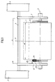
- Fig. 1
- eine schematische Draufsicht eines Teiles eines Wickelrollenwechslers mit einer erfindungsgemäßen Vorrichtung;
- Fig. 2
- einen schematischen Schnitt der erfindungsgemäßen Vorrichtung.
Der linke Lagerarm 6 weist in einer konzentrisch zu einer Drehachse 11 der Wickelrolle 8 liegenden Bohrung 12 eine erste Lagerung, z. B. Nadellager 13, auf, die eine rohrförmige Hohlwelle 14 drehbar und axial verschiebbar aufnimmt.
An diese Hohlwelle 14 greifen Stelleinrichtungen 16 an, die die Hohlwelle 14 axial, auch bei gleichzeitiger Drehung der Hohlwelle 14, verschieben können. Im vorliegenden Beispiel ist das der Wickelrolle 8 abgewandte Ende 17 der Hohlwelle 14 mit einem senkrecht zur Drehachse 11 stehenden, umlaufenden ringförmigen Kragen 18 versehen, den ein nicht rotierender, im Schnitt gesehen, gabelförmiger Ring 19 oder ein bzw. mehrere Gabelsegmente umfassen. Zwischen dem Kragen 18 und dem gabelförmigen Ring 19 können beispielsweise zu beiden Seiten 21, 22 des Kragens 18 Axiallager angeordnet sein. Auch kann z. B. ein Gabelsegment derart gebildet werden, daß zu beiden Seiten des Kragens Kurvenrollen, deren Bolzen über eine Koppel parallel verbunden sind, wirken. Parallel und konzentrisch zur Drehachse 11 sind ein oder mehrere Positionierantriebe angeordnet. Im dargestellten Beispiel sind als Positionierantriebe einfach wirkende, gefederte Pneumatikzylinder 23 verwendet. Ebenso eignen sich andere bekannte Positionierantriebe, wie z. B. Hydraulikzylinder, Spindelantriebe, Linearantriebe usw.. An einem der Wickelrolle 8 zugewandten Ende 24 der Hohlwelle 14 ist bzw. sind ein Drehmomentenübertragungselemente 26 oder mehrere Drehmomentenübertragungselemente 26, im vorliegenden Beispiel eine konzentrisch zur Drehachse 11 liegende ringförmige Scheibe 26 befestigt. Diese Scheibe 26 ist an ihren beiden Planseiten 27, 28 jeweils mit Reibbelägen 29 versehen, so daß die Reibbeläge 29 drehsteif mit der Hohlwelle 14 verbunden sind. Diese Reibbeläge 29 können als ringförmige Scheiben mit einem Außendurchmesser d1, z. B. 700 mm, die einfacherweise mit der Scheibe 26 der Hohlwelle 14 stoffschlüssig verbunden sind, ausgeführt sein. Ebenso sind aber auch nur kreissegmentartige Reibbeläge 29 oder andere Formen möglich. Als Material für die Reibbeläge eignet sich z. B. Gummi oder Polyurethan.
Ein der Wickelrolle 8 abgewandtes Ende 36 der Welle 32 ist mittels einer Kupplung 37, die Drehmomente überträgt und zumindest axialen Versatz der Welle 32 ausgleicht, z. B. Keilwellenverbindung, mit einer Bremseinrichtung 38, z. B. Scheibenbremse, mit einem Antrieb 39, z. B. Drehstrommotor, und mit einem Drehzahlgeber 41, z. B. Inkrementalgeber, gekoppelt.
An dem Lagerarm 6 ist ein Sensor 53, z. B. ein optoelektrischer Reflexionstaster, zum Erfassen eines bestimmten Grenzdurchmessers dG, z. B. 800 mm, der Wickelrolle 8 angebracht.
Die Welle 32 mit ihrem Spannkonus 43 sowie die Hohlwelle 14 mit ihren mit Reibbelägen 29 versehenen Scheibe 26 befindet sich in ihrer wickelrollenfernen Lage, d. h. die Pneumatikzylinder 34 sind ausgefahren. Die Wickelrolle 8 wird derart zwischen die Lagerarme 6, 7 gebracht, daß der Wickelkern 44 mit dem Spannkonus 43 annähernd fluchtet. Durch Einziehen der Pneumatikzylinder 34 der Stelleinrichtung 33 wird der Spannkonus 43 in den Wickelkern 44 geschoben. Anschließend expandieren Backen des Spannkonus 43 durch nichtdargestellte Einrichtungen. Hiermit wird der Wickelkern 44 bzw. die Wickelrolle 8 reib- bzw. formschlüssig mit dem Spannkonus 43 verbunden. Hierauf wird die Drehzahl der Welle 32 mittels des Drehzahlgebers 41 und der Grenzdurchmesser dG der Wickelrolle 8 mittels des Sensors 53 abgefragt. Steht die Welle 32, d. h. die Wickelrolle 8, und entspricht ein tatsächlich vorhandener Durchmesser d2 der Wickelrolle 8 mindestens dem Grenzdurchmesser dG, erfolgt die Freigabe zum axialen Verschieben der Hohlwelle 14 in Richtung Wickelrolle 8. Durch Belüften der Pneumatikzylinder 23 wird die Hohlwelle 14 in Richtung Wickelrolle 8 verschoben, kurz nach Freiwerden der Reibbeläge 29 von den Lagerarmen 6, 7 trifft die Keilwelle 47 auf die Keilnabe 48. Fluchten Kelle 49 und Nuten 54 der Keilwelle 47 nicht mit der Keilnabe 48 wird durch die verjüngten Enden 51, 52 der Kelle 49 eine leichte Drehung der Hohlwelle 14 erzeugt, so daß Keilwelle 47 und Keilnabe 48 bei weiter fortschreitender, axialer Bewegung der Hohlwelle 14 ineinander gleiten. Somit sind Hohlwelle 14 und Welle 32 drehsteif miteinander verbunden und sind somit synchron umlaufend.
Die Hohlwelle 14 wird durch die Pneumatikzylinder 23 axial so weit verschoben, bis die Reibbeläge 29 an einer Stirnfläche 56 der Wickelrolle 8 angepreßt werden. Zwischen Reibbelägen 29 und Wickelrolle 8 besteht nun eine reibschlüssige Verbindung, die Drehmomente übertragen kann.
Ist z. B. nach einem nicht beschriebenen Wechselvorgang die Wickelrolle 8 in Arbeitsfunktion wird die Warenbahn 1 mit gleichförmiger Umfangsgeschwindigkeit bei konstanter Produktionsgeschwindigkeit abgewickelt. Der tatsächliche Durchmesser d2 der Wickelrolle 8 verringert sich und die Drehzahl steigt. Dies wird über den drehzahlgeregelten Antrieb 39 durchgeführt. Ist nun ein Schnellstopp der Wickelrolle 8 notwendig, wird über die Bremseinrichtung 38 ein Bremsmoment an die Welle 32 übertragen. Solange die Reibbeläge 29 mit der Stirnfläche 56 der Wickelrolle 8 zusammenwirken, d. h. solange der Durchmesser d2 der Wickelrolle 8 größer als der Grenzdurchmesser dG ist, wird an der Kupplung 46 das Bremsmoment verzweigt. Die Kupplung 46 überträgt einen Teil des Bremsmomentes an die Hohlwelle 14, welches wiederum mittels der Reibbeläge 29 an die Wickelrolle 8 übertragen wird. Eine Überbeanspruchung des Wickelkerns 44 wird somit ausgeschlossen. Ist kein Schnellstopp erforderlich, werden nach Erreichen des Grenzdurchmessers dG der Wickelrolle 8 durch ein Signal des Sensors 53 die Pneumatikzylinder 23 entlüftet, und durch Federkraft wird die Hohlwelle 14 axial weg von der Wickelrolle 8 verschoben. Hierbei entkoppelt die Kupplung 46 die Welle 32 von der Hohlwelle 14 bevor die Reibbeläge 29 dem Lagerarm 6 erreicht, und die Hohlwelle 14 ist frei drehbar. Durch weiteres Verschieben der Hohlwelle 14 werden die Reibbeläge 29 an den Lagerarm 6 angepreßt. Dadurch wird die Drehbewegung der Hohlwelle 14 abgebremst und gestoppt.
Erfolgt nun ein Schnellstopp wird die deutlich verringerte Masse der Wickelrolle 8 über ein Bremsmoment, was nur von den Spannkonen 43 übertragen wird, abgestoppt.
- 1
- Warenbahn
- 2
- Seitengestell
- 3
- Seitengestell
- 4
- Welle
- 5
- -
- 6
- Lagerarm, linker
- 7
- Lagerarm, rechter
- 8
- Wickelrolle
- 9
- Mittelachse
- 10
- -
- 11
- Drehachse (8)
- 12
- Bohrung (6)
- 13
- Nadellager
- 14
- Hohlwelle
- 15
- -
- 16
- Stelleinrichtung
- 17
- Ende (14)
- 18
- Kragen (14)
- 19
- Ring, gabelförmig (16)
- 20
- -
- 21
- Seite (18)
- 22
- Seite (18)
- 23
- Pneumatikzylinder (16)
- 24
- Ende
- 25
- -
- 26
- Drehmomentenübertragungselement, Scheibe
- 27
- Planflächen (26)
- 28
- Planflächen (26)
- 29
- Reibbelag
- 30
- -
- 31
- Nadellager
- 32
- Welle
- 33
- Stelleinrichtung
- 34
- Pneumatikzylinder (33)
- 35
- -
- 36
- Ende (32)
- 37
- Kupplung
- 38
- Bremseinrichtung
- 39
- Antrieb
- 40
- -
- 41
- Drehzahlgeber
- 42
- Ende (32)
- 43
- Spannkonus
- 44
- Wickelkern
- 45
- -
- 46
- Kupplung, schaltbar
- 47
- Keilwelle
- 48
- Keilnabe
- 49
- Keile (47; 48)
- 50
- -
- 51
- Ende (49)
- 52
- Ende (49)
- 53
- Sensor
- 54
- Nuten (47; 48)
- 55
- -
- 56
- Stirnfläche (8)
- a
- Abstand der Lagerarme
- b
- Breite der Warenbahn (1) bzw. Wickelrolle (8)
- d1
- Außendurchmesser des Reibbelages (29)
- d2
- Durchmesser, vorhandener, der Wickelrolle (8)
- dG
- Grenzdurchmesser der Wickelrolle (8)
Claims (9)
- Vorrichtung zum Abwickeln einer Warenbahn (1), insbesondere einer Papierbahn, in einem Wickelrollenwechsler einer Rotationsdruckmaschine, wobei die Warenbahn (1) auf einem Wickelkern (44) in Form einer Wickelrolle (8) aufgewickelt ist und in Enden des Wickelkernes (44) expandierende, drehbare Spannkonen (43) zur Aufnahme der Wickelrolle (8) eingreifen, die Drehmomente an den Wickelkern (44) und somit an die Wickelrolle (8) übertragen, und wobei mindestens ein Drehmomentenübertragungselement (26) zumindest zeitweise synchron mit den Spannkonen (43) umlaufend vorgesehen ist, das mit einer Stirnfläche (56) der Wickelrolle (8) reibschlüssig zusammenwirkend an- und abstellbar angeordnet ist, wobei die Vorrichtung den Spannkonus und das Drehmomentenübertragungselement enthält, dadurch gekennzeichnet, daß das Drehmomentenübertragungselement (26) unabhängig von und konzentrisch zu dem Spannkonus (43) axial bewegbar angeordnet ist.
- Vorrichtung nach Anspruch 1, dadurch gekennzeichnet, daß das Drehmomentenübertragungselement (26) mittels einer schaltbaren Kupplung (46) drehsteif mit dem Spannkonus (43) verbind- und lösbar angeordnet ist.
- Vorrichtung nach Anspruch 2, dadurch gekennzeichnet, daß die schaltbare Kupplung (46) aus zueinander axial verschiebbarer Keilwelle (47) und Keilnabe (48) besteht.
- Vorrichtung nach Anspruch 1, dadurch gekennzeichnet, daß das Drehmomentenübertragungselement (26) als konzentrisch zur Drehachse (11) liegende, ringförmige Scheibe (26) ausgebildet ist.
- Vorrichtung nach Anspruch 1, dadurch gekennzeichnet, daß als Drehmomentenübertragungselemente (26) segmentartige, an Trägerarmen befestigte Platten vorgesehen sind.
- Vorrichtung nach den Ansprüchen 1 und 5, dadurch gekennzeichnet, daß die Drehmomentenübertragungselemente (26) unabhängig vom Spannkonus (43) mittels der Trägerarme schwenkbar angeordnet sind.
- Vorrichtung nach Anspruch 1, dadurch gekennzeichnet, daß die Planseite (27) der Drehmomentenübertragungselemente (26) mit Reibbelägen (29) versehen ist.
- Vorrichtung nach den Ansprüchen 2 bis 4, dadurch gekennzeichnet, daß eine zweite, der Wickelrolle (8) abgewandte Planseite (28) der Scheibe (26) mit einem Lagerarm (6) des Wickelrollenwechslers bei gelöster Kupplung (46) und wickelrollenferner Lage der Scheibe (26) mittelbar oder unmittelbar (26) zusammenwirkt.
- Vorrichtung nach Anspruch 8, dadurch gekennzeichnet, daß die zweite Planseite (28) der Scheibe (26) mit Reibbelägen (29) versehen ist.
Applications Claiming Priority (2)
| Application Number | Priority Date | Filing Date | Title |
|---|---|---|---|
| DE4437147A DE4437147C1 (de) | 1994-10-18 | 1994-10-18 | Vorrichtung zum Abwickeln einer Warenbahn |
| DE4437147 | 1994-10-18 |
Publications (2)
| Publication Number | Publication Date |
|---|---|
| EP0708047A1 EP0708047A1 (de) | 1996-04-24 |
| EP0708047B1 true EP0708047B1 (de) | 1999-01-20 |
Family
ID=6531022
Family Applications (1)
| Application Number | Title | Priority Date | Filing Date |
|---|---|---|---|
| EP95116030A Expired - Lifetime EP0708047B1 (de) | 1994-10-18 | 1995-10-11 | Verfahren und Vorrichtung zum Abwickeln einer Warenbahn |
Country Status (4)
| Country | Link |
|---|---|
| US (1) | US5860617A (de) |
| EP (1) | EP0708047B1 (de) |
| JP (1) | JPH08231085A (de) |
| DE (2) | DE4437147C1 (de) |
Families Citing this family (7)
| Publication number | Priority date | Publication date | Assignee | Title |
|---|---|---|---|---|
| US6030496A (en) * | 1997-04-16 | 2000-02-29 | Kimberly-Clark Worldwide, Inc. | Making a web |
| DE10024120B4 (de) * | 2000-05-18 | 2005-08-25 | Maschinenfabrik Wifag | Rollenwechsler mit Motorbremse |
| CN100595117C (zh) * | 2003-12-01 | 2010-03-24 | 赛鲁迪公司 | 卷筒更换装置和实施快速更换卷筒的方法 |
| US8070660B2 (en) * | 2005-09-06 | 2011-12-06 | Seidel Gregg A | Device for managing a retractable sheet |
| DE102011080732B4 (de) * | 2011-08-10 | 2017-09-07 | Koenig & Bauer Ag | Verfahren zum Betreiben einer Rollenabspulvorrichtung |
| US11851298B2 (en) * | 2021-05-28 | 2023-12-26 | Renova S.R.L. | Machine for producing cardboard |
| CN115490043B (zh) * | 2022-10-29 | 2024-08-02 | 无锡市竞杰物联网科技有限公司 | 一种可调节放卷阻力的轭铁放卷机 |
Family Cites Families (7)
| Publication number | Priority date | Publication date | Assignee | Title |
|---|---|---|---|---|
| US1788648A (en) * | 1927-08-25 | 1931-01-13 | Wood Newspaper Mach Corp | Paper-roll-controlling device |
| US1883222A (en) * | 1931-01-12 | 1932-10-18 | Wood Newspaper Mach Corp | Paper roll braking device |
| US3019995A (en) * | 1961-04-24 | 1962-02-06 | Raymond H Eckert | Cable applicator and rewind unit |
| US3851834A (en) * | 1973-03-08 | 1974-12-03 | Eastman Kodak Co | Roll drive mechanism |
| CH666063A5 (de) * | 1984-08-31 | 1988-06-30 | Benninger Ag Maschf | Wickelmaschine zum aufwickeln und/oder abwickeln bahnfoermig gefuehrten gutes. |
| DE3521582A1 (de) * | 1985-06-15 | 1986-12-18 | Jagenberg AG, 4000 Düsseldorf | Vorrichtung zum aufspannen von rohrfoermigen wickelkernen, insbesondere von papierbahnen oder aehnliche werkstoffbahnen tragenden wickelkernen |
| IT1253272B (it) * | 1991-10-10 | 1995-07-14 | Gd Spa | Dispositivo per la sostituzione di bobine di materiale in nastro in una macchina operatrice |
-
1994
- 1994-10-18 DE DE4437147A patent/DE4437147C1/de not_active Expired - Fee Related
-
1995
- 1995-10-11 EP EP95116030A patent/EP0708047B1/de not_active Expired - Lifetime
- 1995-10-11 DE DE59504893T patent/DE59504893D1/de not_active Expired - Fee Related
- 1995-10-18 JP JP7269820A patent/JPH08231085A/ja active Pending
-
1997
- 1997-11-17 US US08/971,734 patent/US5860617A/en not_active Expired - Fee Related
Also Published As
| Publication number | Publication date |
|---|---|
| US5860617A (en) | 1999-01-19 |
| EP0708047A1 (de) | 1996-04-24 |
| DE4437147C1 (de) | 1996-05-23 |
| JPH08231085A (ja) | 1996-09-10 |
| DE59504893D1 (de) | 1999-03-04 |
Similar Documents
| Publication | Publication Date | Title |
|---|---|---|
| EP0313859B1 (de) | Vorrichtung zum Ab- oder Aufrollen von bahn- oder bandförmigen Materialien | |
| EP3067304A1 (de) | Spulmaschine | |
| EP2691326B1 (de) | Rollenabspulvorrichtung einer rollen-druckmaschine | |
| EP0708047B1 (de) | Verfahren und Vorrichtung zum Abwickeln einer Warenbahn | |
| EP0863101B1 (de) | Friktionswickelwelle | |
| DE4339766C1 (de) | Vorrichtung zum Verhindern von Schäden bei Rissen von Warenbahnen | |
| EP1708942B1 (de) | Rollenwechsler | |
| EP2881348B1 (de) | Vorrichtung zum Wickeln einer Materialbahn zu einer mehrlagigen Rolle | |
| WO2005054101A2 (de) | Rollenwechsler und verfahren zur durchführung eines fliegenden rollenwechsels | |
| EP1083139B1 (de) | Rollenwickeleinrichtung und Aufwickelverfahren | |
| DE69504010T2 (de) | Maschine, geeignet zur Verwendung von zu Spulen gewickeltem Bahnmaterial | |
| CH629454A5 (en) | Chuck for receiving a spool carrier | |
| DE102005004558A1 (de) | Vorrichtung und Verfahren zur wellenlosen Halterung von Wickelhülsen | |
| EP0676284B1 (de) | Flexodruckmaschine, insbesondere für Mehrfarbendruck | |
| EP0369498B1 (de) | Einrichtung zum Haltern | |
| DE2711752A1 (de) | Kupplungsvorrichtung, insbesondere zur steuerung des garnspulenantriebs bei textilmaschinen | |
| DE102005011335B3 (de) | Rollenbremse mit Rollenabstreifer | |
| EP1731464A2 (de) | Spanndorn zur Lagerung einer Materialrolle | |
| DE3128155C2 (de) | ||
| DE10224839B4 (de) | Spanndorn | |
| EP3102516B1 (de) | Wickeleinrichtung zum aufwickeln eines bahnförmigen materials und verfahren zum wechsel eines wickels in einer wickeleinrichtung | |
| DE102014117521B4 (de) | Hülsenförmiger Wickelkern | |
| EP1789353B1 (de) | Verfahren zur durchführung eines fliegenden rollenwechsels | |
| DE10015181A1 (de) | Rollenschneid- und Wickelmaschine | |
| DE2365384C2 (de) | Spulmaschine mit Spulenrevolver und Ausgleichsgewichtseinrichtung für das Spulengewicht |
Legal Events
| Date | Code | Title | Description |
|---|---|---|---|
| PUAI | Public reference made under article 153(3) epc to a published international application that has entered the european phase |
Free format text: ORIGINAL CODE: 0009012 |
|
| AK | Designated contracting states |
Kind code of ref document: A1 Designated state(s): CH DE FR GB IT LI SE |
|
| 17P | Request for examination filed |
Effective date: 19961012 |
|
| 17Q | First examination report despatched |
Effective date: 19970225 |
|
| GRAG | Despatch of communication of intention to grant |
Free format text: ORIGINAL CODE: EPIDOS AGRA |
|
| GRAG | Despatch of communication of intention to grant |
Free format text: ORIGINAL CODE: EPIDOS AGRA |
|
| GRAG | Despatch of communication of intention to grant |
Free format text: ORIGINAL CODE: EPIDOS AGRA |
|
| GRAH | Despatch of communication of intention to grant a patent |
Free format text: ORIGINAL CODE: EPIDOS IGRA |
|
| GRAH | Despatch of communication of intention to grant a patent |
Free format text: ORIGINAL CODE: EPIDOS IGRA |
|
| GRAA | (expected) grant |
Free format text: ORIGINAL CODE: 0009210 |
|
| RAP1 | Party data changed (applicant data changed or rights of an application transferred) |
Owner name: KOENIG & BAUER AKTIENGESELLSCHAFT |
|
| AK | Designated contracting states |
Kind code of ref document: B1 Designated state(s): CH DE FR GB IT LI SE |
|
| ITF | It: translation for a ep patent filed | ||
| REG | Reference to a national code |
Ref country code: CH Ref legal event code: EP |
|
| ET | Fr: translation filed | ||
| GBT | Gb: translation of ep patent filed (gb section 77(6)(a)/1977) |
Effective date: 19990203 |
|
| REF | Corresponds to: |
Ref document number: 59504893 Country of ref document: DE Date of ref document: 19990304 |
|
| PLBE | No opposition filed within time limit |
Free format text: ORIGINAL CODE: 0009261 |
|
| STAA | Information on the status of an ep patent application or granted ep patent |
Free format text: STATUS: NO OPPOSITION FILED WITHIN TIME LIMIT |
|
| 26N | No opposition filed | ||
| REG | Reference to a national code |
Ref country code: GB Ref legal event code: IF02 |
|
| PGFP | Annual fee paid to national office [announced via postgrant information from national office to epo] |
Ref country code: CH Payment date: 20081027 Year of fee payment: 14 |
|
| PGFP | Annual fee paid to national office [announced via postgrant information from national office to epo] |
Ref country code: SE Payment date: 20081023 Year of fee payment: 14 Ref country code: IT Payment date: 20081022 Year of fee payment: 14 |
|
| PGFP | Annual fee paid to national office [announced via postgrant information from national office to epo] |
Ref country code: FR Payment date: 20081024 Year of fee payment: 14 |
|
| PGFP | Annual fee paid to national office [announced via postgrant information from national office to epo] |
Ref country code: DE Payment date: 20081212 Year of fee payment: 14 |
|
| PGFP | Annual fee paid to national office [announced via postgrant information from national office to epo] |
Ref country code: GB Payment date: 20081028 Year of fee payment: 14 |
|
| REG | Reference to a national code |
Ref country code: CH Ref legal event code: PL |
|
| EUG | Se: european patent has lapsed | ||
| REG | Reference to a national code |
Ref country code: FR Ref legal event code: ST Effective date: 20100630 |
|
| PG25 | Lapsed in a contracting state [announced via postgrant information from national office to epo] |
Ref country code: FR Free format text: LAPSE BECAUSE OF NON-PAYMENT OF DUE FEES Effective date: 20091102 Ref country code: DE Free format text: LAPSE BECAUSE OF NON-PAYMENT OF DUE FEES Effective date: 20100501 |
|
| PG25 | Lapsed in a contracting state [announced via postgrant information from national office to epo] |
Ref country code: LI Free format text: LAPSE BECAUSE OF NON-PAYMENT OF DUE FEES Effective date: 20091031 Ref country code: CH Free format text: LAPSE BECAUSE OF NON-PAYMENT OF DUE FEES Effective date: 20091031 |
|
| PG25 | Lapsed in a contracting state [announced via postgrant information from national office to epo] |
Ref country code: GB Free format text: LAPSE BECAUSE OF NON-PAYMENT OF DUE FEES Effective date: 20091011 |
|
| PG25 | Lapsed in a contracting state [announced via postgrant information from national office to epo] |
Ref country code: IT Free format text: LAPSE BECAUSE OF NON-PAYMENT OF DUE FEES Effective date: 20091011 |
|
| PG25 | Lapsed in a contracting state [announced via postgrant information from national office to epo] |
Ref country code: SE Free format text: LAPSE BECAUSE OF NON-PAYMENT OF DUE FEES Effective date: 20091012 |