EP0708207A1 - Procédé et construction de cadre pour une fondation d'un bâtiment - Google Patents
Procédé et construction de cadre pour une fondation d'un bâtiment Download PDFInfo
- Publication number
- EP0708207A1 EP0708207A1 EP95115573A EP95115573A EP0708207A1 EP 0708207 A1 EP0708207 A1 EP 0708207A1 EP 95115573 A EP95115573 A EP 95115573A EP 95115573 A EP95115573 A EP 95115573A EP 0708207 A1 EP0708207 A1 EP 0708207A1
- Authority
- EP
- European Patent Office
- Prior art keywords
- frame
- frame according
- building
- quiver
- support structure
- Prior art date
- Legal status (The legal status is an assumption and is not a legal conclusion. Google has not performed a legal analysis and makes no representation as to the accuracy of the status listed.)
- Withdrawn
Links
- 238000000034 method Methods 0.000 title claims description 13
- 238000009412 basement excavation Methods 0.000 claims abstract description 8
- 238000004873 anchoring Methods 0.000 claims description 9
- 229910000831 Steel Inorganic materials 0.000 claims description 3
- 238000010276 construction Methods 0.000 claims description 3
- 239000003673 groundwater Substances 0.000 claims description 3
- 239000010959 steel Substances 0.000 claims description 3
- 239000002351 wastewater Substances 0.000 claims description 3
- 238000003780 insertion Methods 0.000 claims 1
- 230000037431 insertion Effects 0.000 claims 1
- 125000006850 spacer group Chemical group 0.000 claims 1
- 238000009415 formwork Methods 0.000 description 3
- 238000005259 measurement Methods 0.000 description 2
- 238000004519 manufacturing process Methods 0.000 description 1
- 239000002184 metal Substances 0.000 description 1
- 239000011148 porous material Substances 0.000 description 1
- 238000009417 prefabrication Methods 0.000 description 1
- 230000002787 reinforcement Effects 0.000 description 1
- 238000007789 sealing Methods 0.000 description 1
- XLYOFNOQVPJJNP-UHFFFAOYSA-N water Substances O XLYOFNOQVPJJNP-UHFFFAOYSA-N 0.000 description 1
- 238000003466 welding Methods 0.000 description 1
- 239000002023 wood Substances 0.000 description 1
Images



Classifications
-
- E—FIXED CONSTRUCTIONS
- E02—HYDRAULIC ENGINEERING; FOUNDATIONS; SOIL SHIFTING
- E02D—FOUNDATIONS; EXCAVATIONS; EMBANKMENTS; UNDERGROUND OR UNDERWATER STRUCTURES
- E02D27/00—Foundations as substructures
- E02D27/01—Flat foundations
Definitions
- the invention relates to a method and a prefabricated frame for the foundation of a building.
- the invention has for its object to provide a method and a framework for the foundation of a building, which completely eliminate the cumbersome measurement explained above and the subsequent erection of formwork.
- a method according to claim 1 and a frame according to claim 4 serve to achieve this object.
- a floor area is first leveled, for example in an excavation opening for a basement of a building. If the basement is to be dispensed with, only a leveling and not a cellar excavation is required. Then a prefabricated frame is placed on the correspondingly roughly oversized floor surface and brought to the desired horizontal level by adjusting the height of at least three different points on its circumference. Then the frame, which also serves as formwork, is poured with concrete.
- the prefabricated frame can have a drainage line for groundwater surrounding its circumference, which therefore does not have to be subsequently inserted around the foundation, as is required in the case of the ring drains customary up to now.
- the frame can also be prefabricated with a waste water drainage used to drain the domestic water.
- the frame which is preferably welded together from sheet steel profiles, including the stroke adjustment device, is "lost", ie can only be used once for each building. With the prefabrication of the frame additional costs are far outweighed by the saving in working time, so that the method and the frame according to the invention, particularly in prefabricated construction, lead to considerable cost savings.
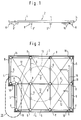
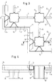
- FIGS. 1 and 2 A frame for the foundation of a building is shown overall in FIGS. 1 and 2 and in detail in FIGS. 3 to 6.
- the frame has a lattice structure 2 made of welded sheet steel profiles, namely the circumference of the frame surrounding L-profiles 4, which are open inwards and upwards, and hollow profiles 6 drawn into the lattice support structure for reinforcement, which are formed as square tubes in the exemplary embodiment shown.
- a lattice structure 2 made of welded sheet steel profiles, namely the circumference of the frame surrounding L-profiles 4, which are open inwards and upwards, and hollow profiles 6 drawn into the lattice support structure for reinforcement, which are formed as square tubes in the exemplary embodiment shown.
- customary profiles of a different design and, instead of two profile types, uniform profiles throughout, for example U, T or H profiles.
- an upwardly open quiver 8 is arranged for receiving building supports. 3 and 4, the quiver 8 arranged near the frame circumference are welded to the upright legs 4 'of the L-profiles by means of V-shaped sheets 10.
- tension cables 12 are stretched diagonally to stiffen the lattice structure 2.
- tension cables 12 which can only be stretched between the four main corners of the lattice structure, there are rectangular or round struts, such as e.g. indicated at 13 in Fig. 2, can be used.
- the lattice structure can also be made of plastic or wood instead of metal profiles. It can be supplemented by a floor, in particular if the ground is sloping / uneven, in order to avoid unnecessary consumption of concrete by closing the lattice structure 2 downwards.
- reference numeral 14 denotes a drainage line made of a porous material with a drain, not shown, at a specific point on the frame circumference, which is used to drain groundwater. According to FIG. 4, the lower, horizontal leg 4 ′′ of the L-profile is somewhat higher than the lower edge of the drainage line.
- FIGS. 1 and 2 only in FIGS. 1 and 2 is an additional waste water drain 16 drawn in, which is preassembled on the frame by connecting to square tubes 6 and tensioning cables 12 of the lattice structure 2.
- FIG. 2 At the six corners of the frame a total of six stroke adjusting devices 18 are indicated in FIG. 2 between L-profiles 4 and square tubes 6 running parallel thereto, which are shown in detail in FIGS. 5 and 6, but in FIGS. 3 and 4 of the Are not drawn for the sake of clarity.
- Each stroke adjustment device 18 has a rotatable threaded spindle 20 which is screwed into a nut 22 welded to the L-profile 4.
- the foot of the spindle 20 is designed as a ball 23 and is held between a spherical-galotte-shaped recess 26 of a base plate 21 and a tab 24 connected to the edge of the recess at 25, which allows the spindle 20 to pass through an opening 27 upwards and with an arched upwards Collar 28 holds the ball 23 in the recess 26 and thus prevents the spindle 20 from axially shifting.
- the spindle 20 is by means of a hand tool or an auxiliary power tool, e.g. B. hydraulic, rotatable at 29.
- the frame can be adjusted to a desired horizontal level.
- the webs 4 ', 4' 'of the L-profiles can be provided with flanges 41 or ribs 42 for stiffening.
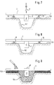
- the frame is lowered by means of a crane (not shown) in the direction of arrow a in FIG. 7 onto the leveled floor surface 100, in the floor surface 100 at all those locations where the anchoring sections 8 'of the quiver 8 are down from the frame protrude, to accommodate these anchoring sections 8 ', well-dimensioned holes 102 are made in the ground.
- the lattice support structure 2 of the frame is aligned to a predetermined horizontal level by means of the stroke adjustment devices 18.
- the distance between the lattice support structure 2 and the floor surface 100 is completely filled with gravel 103 or the like, whereupon the interior of the frame is then simultaneously poured with the holes 102 with concrete. In this way, the frame is reliably anchored to the ground.
- sealing covers 8'' are removed from the upper openings of the quiver 8, so that building supports 106 enter the cavities of the quiver from above Fig. 10 can be used.
- the building supports 106 are secured in the next step according to FIG. 11 by wedging and pouring concrete at 107.
- the perspective representation of the cast foundation plate 101 according to FIG. 12 shows an intermediate state between the method steps according to FIGS. 9 and 10, wherein the closure cover 8 ′′ has been removed from the quiver 8, but the building supports 106 have not yet been inserted into the quiver 8 have been.
- FIG. 14 shows a state in which basement walls 110 are drawn in on the foundation plate between the building supports 106.
Landscapes
- Engineering & Computer Science (AREA)
- Life Sciences & Earth Sciences (AREA)
- General Life Sciences & Earth Sciences (AREA)
- Mining & Mineral Resources (AREA)
- Paleontology (AREA)
- Civil Engineering (AREA)
- General Engineering & Computer Science (AREA)
- Structural Engineering (AREA)
- Foundations (AREA)
- Forms Removed On Construction Sites Or Auxiliary Members Thereof (AREA)
Applications Claiming Priority (2)
| Application Number | Priority Date | Filing Date | Title |
|---|---|---|---|
| DE4437292 | 1994-10-18 | ||
| DE19944437292 DE4437292C2 (de) | 1994-10-18 | 1994-10-18 | Verfahren und Rahmen zum Fundamentieren eines Gebäudes |
Publications (1)
| Publication Number | Publication Date |
|---|---|
| EP0708207A1 true EP0708207A1 (fr) | 1996-04-24 |
Family
ID=6531123
Family Applications (1)
| Application Number | Title | Priority Date | Filing Date |
|---|---|---|---|
| EP95115573A Withdrawn EP0708207A1 (fr) | 1994-10-18 | 1995-10-02 | Procédé et construction de cadre pour une fondation d'un bâtiment |
Country Status (6)
| Country | Link |
|---|---|
| EP (1) | EP0708207A1 (fr) |
| CZ (1) | CZ270295A3 (fr) |
| DE (1) | DE4437292C2 (fr) |
| HR (1) | HRP950522A2 (fr) |
| HU (1) | HUT77825A (fr) |
| PL (1) | PL310990A1 (fr) |
Cited By (1)
| Publication number | Priority date | Publication date | Assignee | Title |
|---|---|---|---|---|
| ES2200603A1 (es) * | 2000-06-01 | 2004-03-01 | Montero Jesus Manuel Nunez | Proyecto numarmont. |
Families Citing this family (1)
| Publication number | Priority date | Publication date | Assignee | Title |
|---|---|---|---|---|
| DE10256886B4 (de) * | 2002-11-22 | 2011-10-06 | M. Findorff Bau Gmbh | Verfahren und Vorrichtung zum Fundamentieren und zur Herstellung von Mauerwerk |
Citations (3)
| Publication number | Priority date | Publication date | Assignee | Title |
|---|---|---|---|---|
| FR2242520A1 (fr) * | 1973-08-29 | 1975-03-28 | Marley Homes Ltd | |
| US4380329A (en) * | 1980-08-25 | 1983-04-19 | Nunno Louis E M | Footing jig for positioning fasteners |
| FR2591259A1 (fr) * | 1985-12-10 | 1987-06-12 | Malie Louis | Plot prefabrique destine a supporter un pilier de charpente ou un element de fondation |
Family Cites Families (4)
| Publication number | Priority date | Publication date | Assignee | Title |
|---|---|---|---|---|
| SE338950B (fr) * | 1969-05-28 | 1971-09-20 | K Algers | |
| DE2011145A1 (de) * | 1970-03-10 | 1971-09-23 | Schmekyes, Bruno, 5090 Leverkusen | Verfahren zur Herstellung von Fertigbauten |
| DE3442912A1 (de) * | 1984-11-24 | 1986-06-05 | Eggeling, Ernst, 4600 Dortmund | Verfahren zur herstellung eines koecherfundamentes |
| DE3608386A1 (de) * | 1986-03-13 | 1987-09-17 | Carl Martin Hansen | Fundamentschalkasten |
-
1994
- 1994-10-18 DE DE19944437292 patent/DE4437292C2/de not_active Expired - Fee Related
-
1995
- 1995-10-02 EP EP95115573A patent/EP0708207A1/fr not_active Withdrawn
- 1995-10-11 HU HU9502954A patent/HUT77825A/hu unknown
- 1995-10-16 CZ CZ952702A patent/CZ270295A3/cs unknown
- 1995-10-17 PL PL31099095A patent/PL310990A1/xx unknown
- 1995-10-18 HR HRP950522 patent/HRP950522A2/hr not_active Application Discontinuation
Patent Citations (3)
| Publication number | Priority date | Publication date | Assignee | Title |
|---|---|---|---|---|
| FR2242520A1 (fr) * | 1973-08-29 | 1975-03-28 | Marley Homes Ltd | |
| US4380329A (en) * | 1980-08-25 | 1983-04-19 | Nunno Louis E M | Footing jig for positioning fasteners |
| FR2591259A1 (fr) * | 1985-12-10 | 1987-06-12 | Malie Louis | Plot prefabrique destine a supporter un pilier de charpente ou un element de fondation |
Cited By (1)
| Publication number | Priority date | Publication date | Assignee | Title |
|---|---|---|---|---|
| ES2200603A1 (es) * | 2000-06-01 | 2004-03-01 | Montero Jesus Manuel Nunez | Proyecto numarmont. |
Also Published As
| Publication number | Publication date |
|---|---|
| CZ270295A3 (en) | 1996-05-15 |
| PL310990A1 (en) | 1996-04-29 |
| HRP950522A2 (en) | 1997-06-30 |
| HU9502954D0 (en) | 1995-12-28 |
| HUT77825A (hu) | 1998-08-28 |
| DE4437292A1 (de) | 1996-05-02 |
| DE4437292C2 (de) | 1998-07-02 |
Similar Documents
| Publication | Publication Date | Title |
|---|---|---|
| DE69913977T2 (de) | Methode zum herstellen eines plattenbodens und ein plattenboden | |
| DE2920873C2 (de) | Vorrichtung für die Anpflanzung von Bäumen u.dgl., insbesondere in Verkehrsbereichen | |
| WO2014067884A1 (fr) | Procédé de construction d'une tour en béton armé | |
| DE1138208B (de) | Verfahren und Vorrichtung zum Einrichten von mehrgeschossigen, unterkellerten Gebaeuden | |
| EP4038240B1 (fr) | Fondation pour turbine d'éolienne | |
| DE3719523A1 (de) | Fundierungs- oder absicherungselement | |
| DE2242131C3 (de) | Transformatorstation, Umspannstation o.dgl | |
| DE4437292C2 (de) | Verfahren und Rahmen zum Fundamentieren eines Gebäudes | |
| WO2008141620A2 (fr) | Dispositifs de coffrage et procédé de fabrication de structures monolithiques en béton coulé | |
| EP3299524B1 (fr) | Mur en elements prefabriques et son procede de fabrication | |
| EP0515724A1 (fr) | Méthode et module préfabriqué pour la construction d'édifices et des bâtiments | |
| EP0645501B1 (fr) | Méthode pour la production de modules préfabriqués pour la construction de bâtiments et module préfabriqué | |
| DE19941603C2 (de) | Stahlbetonteil zur Herstellung von Fundamenten für Bauwerke | |
| DE202004006629U1 (de) | Bodenplatte mit Kellerwand | |
| DE102009021143A1 (de) | Fundamentkorb, Fundament und Verfahren zur Bildung eines Fundaments | |
| DE9314567U1 (de) | Vorgefertigter Modul | |
| DE2636168C2 (de) | Gebäude aus tragenden vorgefertigten Bauteilen | |
| DE3110286A1 (de) | "schwimmbecken" | |
| DE3445212C2 (fr) | ||
| AT372734B (de) | Baukonstruktion | |
| DE4141331A1 (de) | Fachwerkbruecke und verfahren zu deren herstellung sowie vorrichtung zur durchfuehrung des verfahrens | |
| AT523783B1 (de) | Verkleidung für eine Wandschale und Verfahren zur Herstellung | |
| DE4407191A1 (de) | Verfahren zur Herstellung von Stützen oder Säulen bei der Erstellung von Gebäuden u. dgl. sowie aus einer rohrförmigen Schalungsform bestehende Vorrichtung zur Herstellung von Stützen oder Säulen | |
| DE4225953C2 (fr) | ||
| DE3415738A1 (de) | Verfahren zum herstellen von gruendungen, insbesondere pfahlgruendungen |
Legal Events
| Date | Code | Title | Description |
|---|---|---|---|
| PUAI | Public reference made under article 153(3) epc to a published international application that has entered the european phase |
Free format text: ORIGINAL CODE: 0009012 |
|
| AK | Designated contracting states |
Kind code of ref document: A1 Designated state(s): AT BE CH DE ES FR GB IT LI NL |
|
| 17P | Request for examination filed |
Effective date: 19960924 |
|
| 17Q | First examination report despatched |
Effective date: 19970127 |
|
| GRAG | Despatch of communication of intention to grant |
Free format text: ORIGINAL CODE: EPIDOS AGRA |
|
| GRAG | Despatch of communication of intention to grant |
Free format text: ORIGINAL CODE: EPIDOS AGRA |
|
| GRAH | Despatch of communication of intention to grant a patent |
Free format text: ORIGINAL CODE: EPIDOS IGRA |
|
| STAA | Information on the status of an ep patent application or granted ep patent |
Free format text: STATUS: THE APPLICATION HAS BEEN WITHDRAWN |
|
| 18W | Application withdrawn |
Withdrawal date: 19990115 |