EP0708213A1 - Système de fixation pour panneaux compacts - Google Patents
Système de fixation pour panneaux compacts Download PDFInfo
- Publication number
- EP0708213A1 EP0708213A1 EP95116076A EP95116076A EP0708213A1 EP 0708213 A1 EP0708213 A1 EP 0708213A1 EP 95116076 A EP95116076 A EP 95116076A EP 95116076 A EP95116076 A EP 95116076A EP 0708213 A1 EP0708213 A1 EP 0708213A1
- Authority
- EP
- European Patent Office
- Prior art keywords
- profile
- fastening system
- compact
- sections
- compact plate
- Prior art date
- Legal status (The legal status is an assumption and is not a legal conclusion. Google has not performed a legal analysis and makes no representation as to the accuracy of the status listed.)
- Granted
Links
Images

Classifications
-
- E—FIXED CONSTRUCTIONS
- E04—BUILDING
- E04F—FINISHING WORK ON BUILDINGS, e.g. STAIRS, FLOORS
- E04F13/00—Coverings or linings, e.g. for walls or ceilings
- E04F13/07—Coverings or linings, e.g. for walls or ceilings composed of covering or lining elements; Sub-structures therefor; Fastening means therefor
- E04F13/08—Coverings or linings, e.g. for walls or ceilings composed of covering or lining elements; Sub-structures therefor; Fastening means therefor composed of a plurality of similar covering or lining elements
- E04F13/0801—Separate fastening elements
- E04F13/0803—Separate fastening elements with load-supporting elongated furring elements between wall and covering elements
- E04F13/081—Separate fastening elements with load-supporting elongated furring elements between wall and covering elements with additional fastening elements between furring elements and covering elements
- E04F13/0816—Separate fastening elements with load-supporting elongated furring elements between wall and covering elements with additional fastening elements between furring elements and covering elements the additional fastening elements extending into the back side of the covering elements
- E04F13/0819—Separate fastening elements with load-supporting elongated furring elements between wall and covering elements with additional fastening elements between furring elements and covering elements the additional fastening elements extending into the back side of the covering elements inserted into grooves in the back side of the covering elements
Definitions
- the invention relates to a fastening system for compact panels made of one or more fiber layers which are hot-pressed together and impregnated with resin and which are coated on the outside on at least one side with a decorative layer, for invisible mounting on a base body.
- compact sheets especially so-called HPL (high pressure laminate) compact sheets
- HPL high pressure laminate
- compact panels also includes panels that have a structure very similar to the DIN or ISO standard.
- the components of such compact sheets are made from the same materials in the same high-pressure presses as all HPL sheets and, depending on the molding process, contain adhesive layers from case to case.
- the decorative coloring of the compact panel on one or both sides can be carried out on a smooth or structured surface.
- HPL compact panels The core of HPL compact panels is very strong and can therefore absorb large forces without breaking or deforming.
- Such panels are used in particular for facade and wall cladding due to their high weather and shape stability, care being taken to ensure that the panels are fastened is invisible from the outside on a wall or a body.
- Such invisible fastenings have so far been realized for HPL compact panels in such a way that these panels are glued or fastened by means of screws.
- screw connections these are made directly with the compact panels, with the dowels generally being inserted in the panels.
- the connection to the wall behind or to the basic body located behind is made via brackets.
- the screw connections are generally made using dowels in the panels.
- tongue and groove connections or guide grooves and slides in engagement therewith which have the same cross-section as the guide groove and are fitted into them .
- the object of the invention is a for panels that are used for weatherproof cladding To create fastening system in which the plates can be fastened over the entire size of their format and a largely tension-free connection of plates and the wall or base body behind it is made possible.
- the fastening system consists of a profile that connects the compact plates and a wall or a base body, and that in the sides of the base plate facing the base body are milled, the cross-sections of which sections with the Profiles cover.
- the individual milling has a depth that is in the range from one third to half the thickness d of the compact plate and the milling extends over part or over the entire dimension of the compact plate.
- the invention is further developed in such a way that the milling has a dovetail cross section and receives a dovetail section of the profile.
- the compact plates are freely movable in the direction of the longitudinal axis of the profile, so that the thermal and hygroscopic differences in the materials occurring due to different materials of the compact plate and wall or base body are recorded and can be compensated.
- the profile depending on the milling and profile dimensioning as well as the profile material, there is an increase in the bending stiffness of the combination compact plate - profile, in the direction of the longitudinal axis of the profile, perpendicular to the plate surface. Correct dimensioning keeps the connection between the compact panel - profile - wall or base body tension-free.
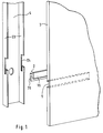
- a compact plate 3 has a milling 5 in the lower part with a dovetail cross section.
- the milling 5 extends over the entire length of the compact plate 3 or only over a section of the compact plate, as is indicated in FIG. 1 by the dashed lines.
- a profile 2 is composed of two sections 10 and 20, with one section 20 one upside down L-shaped cross section.
- the other section 10 connects centrally to the horizontal leg of section 20 and has a dovetail cross-section that can be inserted seamlessly into the milling 5 of the compact plate 3.
- the section 20 can be positively inserted into an incision 24 in a base body 4.
- This base body 4 is, for example, a U-shaped metal support, which is arranged vertically in a steel frame, which defines the outline of a house or which is attached to the wall of a building or a room as a substructure for the wall covering.
- the incision 24 is located in the two side walls 23 of the base body 4.
- the material of the profile 2 is generally different from the material of the compact plate 3, which consists of one or more resin-impregnated fiber layers which form the core of the compact plate.
- the two outer sides of this core are each covered with a decorative plate. Decorative layer coated.
- FIG 2 shows a detail and on an enlarged scale, the fastening system 1 with the profile 2 and the compact plate 3.
- the section 10 of the profile 2 is inserted.
- the outline or cross section of the section 10 is also dovetail-shaped and inserts without play.
- the milling 5 has a depth t which is in the range from one third to half the thickness d, cf. Figures 2 and 3a, the compact plate.
- the small depth of the milling 5 is possible because the core of the compact plate 3 has great strength, so that even such a small depth ensures a mechanically very stable connection of the profile 2 to the compact plate 3.
- the profile 2 is inserted with its portion 10 laterally into the milling 5.
- the length of the profile 2 can be chosen so that it extends over a partial length, the total length of a compact plate or over two or more compact plates.
- the profile 2 can also be connected to a base body or to a wall in a different way than shown in FIG. 1. For example, it is possible to screw section 20 of profile 2 to any number of fastening points with a wall or a base body. Due to the connection between profile 2 and the compact plate 3, similar to a tongue and groove connection, the assembly is largely stress-free if the cross sections are dimensioned correctly.
- an increase in the bending rigidity in the direction of the longitudinal axis of the profile (or milling) of the compact plate 3 perpendicular to its surface is obtained by connecting these two parts.
- the compact plate 3 can move freely in the direction of the longitudinal axis of the profile or the milling 5, so that differences in the thermal and hygroscopic effects of the different materials for the profile 2 and the compact plate 3 can be absorbed and compensated for.
- FIGS. 3a to 3d show different fastening systems, in which the compact plates and the profiles are adapted to one another.
- the depth of the milling 5 is one third of the thickness d of the compact plate 3.
- Figure 3b shows a fastening system 1, in which an end piece of a profile 14 is V-shaped and sections 11, 11 form the end sections of the V-shape.
- the opening angle ⁇ of the V shape is 50 up to 100 °.
- the milling 17, 17 consists of two cross sections 7, 7, which are arranged in mirror image to a perpendicular to the compact plate 3 and which are oblique to the surface of the Compact plate 3 run. These cross sections also form an angle of 50 to 100 ° with one another and take up the square-shaped sections 11, 11 of the profile 14.
- the depth of the milling 17, 17 is approximately half the thickness d / 2 of the compact plate 3.
- the end faces of the sections 11, 11 are oriented obliquely to the surface of the compact plate 3.
- the fastening system 1 according to FIG. 3c is formed from a compact plate 3 and a profile 15, the end piece of which has a shape similar to a two-pronged fork.
- the central piece 20 of the profile 15, which runs vertically in FIG. 3c, is adjoined by sections 12, 12 which run obliquely upwards and downwards.
- the end faces 21, 21 of the partial surface 12, 12 are oriented obliquely with respect to the surface of the compact plate 3.
- the middle piece 20 of the profile 15 ends with the surface of the compact plate 3.
- the angle enclosed by the two sections 12, 12 can be in the range from 60 to 120 °.
- a milling 18, 18 is provided therein from two cross sections 8, 8 arranged in mirror image to a perpendicular to the compact plate. These cross sections 8, 8 run obliquely and enclose the same angle as the sections 12, 12 with each other. The depth of the milling 18, 18 is half the thickness d / 2 of the compact plate 3.
- FIG. 3d A further fastening system 1 is shown in FIG. 3d, which is configured similarly to that according to FIG. 3c.
- a profile 16 has a fork-shaped, two-pronged shape with a vertical center piece 23 and adjoining sections 13, 13 which run obliquely upwards and downwards.
- the end faces 22, 22 of the sections 13, 13 are aligned parallel to the surface of the compact plate 3.
- a milling 19, 19 is adapted to the orientation of the sections 13, 13 of the profile 16.
- the milling 19, 19 has a depth equal to a third of the thickness d of the compact plate 3.
- the center piece 23 of the profile 16 lies against the surface of the plate 3.
- fastening system consisting of profile and compact plate also deviating from the shapes and cross sections shown in the exemplary embodiments without deviating from the subject matter of the invention.
- the fastening system according to the invention is not limited to the use of compact plates of the type described, rather it is also suitable for other plate materials.
Landscapes
- Engineering & Computer Science (AREA)
- Architecture (AREA)
- Civil Engineering (AREA)
- Structural Engineering (AREA)
- Finishing Walls (AREA)
- Connection Of Plates (AREA)
- Joining Of Building Structures In Genera (AREA)
Applications Claiming Priority (2)
| Application Number | Priority Date | Filing Date | Title |
|---|---|---|---|
| DE9416917U DE9416917U1 (de) | 1994-10-20 | 1994-10-20 | Befestigungssystem für Kompaktplatten |
| DE9416917U | 1994-10-20 |
Publications (2)
| Publication Number | Publication Date |
|---|---|
| EP0708213A1 true EP0708213A1 (fr) | 1996-04-24 |
| EP0708213B1 EP0708213B1 (fr) | 2000-05-03 |
Family
ID=6915132
Family Applications (1)
| Application Number | Title | Priority Date | Filing Date |
|---|---|---|---|
| EP95116076A Expired - Lifetime EP0708213B1 (fr) | 1994-10-20 | 1995-10-12 | Système de fixation avec panneaux compacts |
Country Status (2)
| Country | Link |
|---|---|
| EP (1) | EP0708213B1 (fr) |
| DE (2) | DE9416917U1 (fr) |
Cited By (8)
| Publication number | Priority date | Publication date | Assignee | Title |
|---|---|---|---|---|
| EP0943041A4 (fr) * | 1996-09-05 | 1999-12-01 | James Hardie Res Pty Ltd | Systeme de montage de panneau de revetement ameliore |
| DE102005019977A1 (de) * | 2005-04-27 | 2006-11-09 | Deutsche Steinzeug Cremer & Breuer Ag | Fassadensystem aus keramischen Fassadenplatten zum Einsatz als vorgehängte hinterlüftete Fassade an einer tragenden Bauwerkswand |
| WO2007032592A1 (fr) | 2005-09-16 | 2007-03-22 | Lg Chem, Ltd. | Kit d’installation de panneaux et procédé pour installer des panneaux l’utilisant |
| US7993570B2 (en) | 2002-10-07 | 2011-08-09 | James Hardie Technology Limited | Durable medium-density fibre cement composite |
| US7998571B2 (en) | 2004-07-09 | 2011-08-16 | James Hardie Technology Limited | Composite cement article incorporating a powder coating and methods of making same |
| ITMS20110001A1 (it) * | 2011-01-28 | 2012-07-29 | Cesare Ferrari | Elemento metallico o plastico, composto da un unico pezzo, per il montaggio ad aggancio, di pannelli da rivestimento. |
| US8769901B2 (en) | 2010-05-28 | 2014-07-08 | The Diller Corporation | Cladding system for building laminates |
| US8993462B2 (en) | 2006-04-12 | 2015-03-31 | James Hardie Technology Limited | Surface sealed reinforced building element |
Families Citing this family (8)
| Publication number | Priority date | Publication date | Assignee | Title |
|---|---|---|---|---|
| AT404746B (de) * | 1995-05-23 | 1999-02-25 | Falb Karl | Plattenbefestigung |
| DE19753768A1 (de) | 1997-12-04 | 1999-06-10 | Trespa Int Bv | Montagesystem für Platten zur Fassadenverkleidung von Gebäuden |
| US6689451B1 (en) | 1999-11-19 | 2004-02-10 | James Hardie Research Pty Limited | Pre-finished and durable building material |
| DE10022615C2 (de) * | 2000-04-18 | 2002-07-18 | Klaus Winter | Hinterlüftete Fassadenverkleidung |
| CN1308560C (zh) | 2001-04-03 | 2007-04-04 | 詹姆斯哈迪国际财金公司 | 板壁板条及其制造方法 |
| DE10163508A1 (de) | 2001-12-21 | 2003-07-03 | Trespa Int Bv | Plattenmontagesystem zum Erstellen einer Wand |
| US8281535B2 (en) | 2002-07-16 | 2012-10-09 | James Hardie Technology Limited | Packaging prefinished fiber cement articles |
| DK1534511T3 (da) | 2002-07-16 | 2012-07-09 | Hardie James Technology Ltd | Emballage til præfabrikerede fibercementprodukter |
Citations (5)
| Publication number | Priority date | Publication date | Assignee | Title |
|---|---|---|---|---|
| FR1530114A (fr) * | 1966-06-30 | 1968-06-21 | S Guffanti & Ratti Di Raineri | Procédé pour fixer des lames de revêtement sur des parois ou des murs et éléments pour sa mise en oeuvre |
| DE2364224A1 (de) * | 1973-12-22 | 1975-11-13 | Guenther Dipl Ing Koch | Wandbildendes bautafelsystem, insbesondere vorhang-fassadensystem mit bautafeln aus kunstharzbeton |
| DE2460880A1 (de) * | 1974-12-21 | 1976-06-24 | Horst Hahn | Anker zum verbinden von bauelementen untereinander oder mit einem verankerungsgrund |
| EP0081147A1 (fr) * | 1981-12-04 | 1983-06-15 | Hoechst Aktiengesellschaft | Panneau formé décoratif, son procédé de fabrication et son application |
| WO1993001418A1 (fr) * | 1991-07-11 | 1993-01-21 | ISOVOLTA Österreichische Isolierstoffwerke Aktiengesellschaft | Dispositif pour la fixation invisible de panneaux a des structures porteuses |
-
1994
- 1994-10-20 DE DE9416917U patent/DE9416917U1/de not_active Expired - Lifetime
-
1995
- 1995-10-12 EP EP95116076A patent/EP0708213B1/fr not_active Expired - Lifetime
- 1995-10-12 DE DE59508257T patent/DE59508257D1/de not_active Expired - Fee Related
Patent Citations (5)
| Publication number | Priority date | Publication date | Assignee | Title |
|---|---|---|---|---|
| FR1530114A (fr) * | 1966-06-30 | 1968-06-21 | S Guffanti & Ratti Di Raineri | Procédé pour fixer des lames de revêtement sur des parois ou des murs et éléments pour sa mise en oeuvre |
| DE2364224A1 (de) * | 1973-12-22 | 1975-11-13 | Guenther Dipl Ing Koch | Wandbildendes bautafelsystem, insbesondere vorhang-fassadensystem mit bautafeln aus kunstharzbeton |
| DE2460880A1 (de) * | 1974-12-21 | 1976-06-24 | Horst Hahn | Anker zum verbinden von bauelementen untereinander oder mit einem verankerungsgrund |
| EP0081147A1 (fr) * | 1981-12-04 | 1983-06-15 | Hoechst Aktiengesellschaft | Panneau formé décoratif, son procédé de fabrication et son application |
| WO1993001418A1 (fr) * | 1991-07-11 | 1993-01-21 | ISOVOLTA Österreichische Isolierstoffwerke Aktiengesellschaft | Dispositif pour la fixation invisible de panneaux a des structures porteuses |
Cited By (12)
| Publication number | Priority date | Publication date | Assignee | Title |
|---|---|---|---|---|
| EP0943041A4 (fr) * | 1996-09-05 | 1999-12-01 | James Hardie Res Pty Ltd | Systeme de montage de panneau de revetement ameliore |
| US6226947B1 (en) | 1996-09-05 | 2001-05-08 | James Hardie Research Pty Limited | Cladding board mounting system |
| US7993570B2 (en) | 2002-10-07 | 2011-08-09 | James Hardie Technology Limited | Durable medium-density fibre cement composite |
| US7998571B2 (en) | 2004-07-09 | 2011-08-16 | James Hardie Technology Limited | Composite cement article incorporating a powder coating and methods of making same |
| DE102005019977A1 (de) * | 2005-04-27 | 2006-11-09 | Deutsche Steinzeug Cremer & Breuer Ag | Fassadensystem aus keramischen Fassadenplatten zum Einsatz als vorgehängte hinterlüftete Fassade an einer tragenden Bauwerkswand |
| DE102005019977B4 (de) * | 2005-04-27 | 2007-12-27 | Deutsche Steinzeug Cremer & Breuer Ag | Fassadensystem aus keramischen Fassadenplatten zum Einsatz als vorgehängte hinterlüftete Fassade an einer tragenden Bauwerkswand |
| WO2007032592A1 (fr) | 2005-09-16 | 2007-03-22 | Lg Chem, Ltd. | Kit d’installation de panneaux et procédé pour installer des panneaux l’utilisant |
| EP1924753A4 (fr) * | 2005-09-16 | 2010-04-28 | Lg Chemical Ltd | Kit d installation de panneaux et procédé pour installer des panneaux l utilisant |
| US8993462B2 (en) | 2006-04-12 | 2015-03-31 | James Hardie Technology Limited | Surface sealed reinforced building element |
| US8769901B2 (en) | 2010-05-28 | 2014-07-08 | The Diller Corporation | Cladding system for building laminates |
| US8991127B2 (en) | 2010-05-28 | 2015-03-31 | The Diller Corporation | Cladding system for building laminates |
| ITMS20110001A1 (it) * | 2011-01-28 | 2012-07-29 | Cesare Ferrari | Elemento metallico o plastico, composto da un unico pezzo, per il montaggio ad aggancio, di pannelli da rivestimento. |
Also Published As
| Publication number | Publication date |
|---|---|
| EP0708213B1 (fr) | 2000-05-03 |
| DE9416917U1 (de) | 1994-12-01 |
| DE59508257D1 (de) | 2000-06-08 |
Similar Documents
| Publication | Publication Date | Title |
|---|---|---|
| EP0708213B1 (fr) | Système de fixation avec panneaux compacts | |
| DE3402923A1 (de) | Verbundplatte sowie verfahren zur herstellung einer verbundplatte | |
| DE19846599A1 (de) | Verfahren zum Aufbau von Trennwänden | |
| DE69713665T2 (de) | Wärmegedämmte Metallwandkonstruktion | |
| WO2008092699A1 (fr) | Dispositif d'inspection, en particulier élément de recouvrement d'inspection | |
| WO2009006926A1 (fr) | CONCEPT DE PANNEAU DE PAROI À 45º | |
| DE3224883A1 (de) | Verfahren zur herstellung eines gehaeuserahmens mit abgerundeten ecken, insbesondere fuer rundfunk- und fernsehgeraete, und damit hergestellter gehaeuserahmen | |
| DE9117174U1 (de) | Türblatt und Bausatz für ein Türblatt | |
| EP0249085B1 (fr) | Poteau profilé configuré en tant que profilé pour cloison légère | |
| DE4010920A1 (de) | Feuerschutztor | |
| DE19835106B4 (de) | Eckschutzschiene für Leichtbauplatten | |
| DE2252501A1 (de) | Tafelfoermiges verbundelement | |
| DE2501330B2 (de) | Wand mit einem aus stabförmigen Bauelementen zusammengesetzten Traggerippe | |
| DE3702298C2 (fr) | ||
| EP3015614A1 (fr) | Plaque murale pour cloison seche en materiau derive du bois et montage de mur et procede de fabrication | |
| DE8519520U1 (de) | Stützstab für zweischalige Leichtbau-Innenwände hoher Schalldämmung | |
| EP0109968B1 (fr) | Rayonnage en bois | |
| DE8002299U1 (de) | Wandelement in fertigbauweise | |
| DE10246039B4 (de) | Bausatz für ein Gebäude | |
| DE2142606C3 (de) | Zweischalige schalldämmende Innentrennwand und Verfahren zur Herstellung derselben | |
| DE3444528A1 (de) | Verfahren zur herstellung einer verbundplatte | |
| EP0665344A1 (fr) | Procédé pour la fabrication d'un panneau de construction et panneau de construction | |
| DE29809840U1 (de) | Leichtbauwand | |
| DE8507109U1 (de) | Holzregal | |
| DE8404887U1 (de) | Selbsttragendes platten- bzw. brettfoermiges element fuer die innenverkleidung von waenden, decken od. dgl. |
Legal Events
| Date | Code | Title | Description |
|---|---|---|---|
| PUAI | Public reference made under article 153(3) epc to a published international application that has entered the european phase |
Free format text: ORIGINAL CODE: 0009012 |
|
| AK | Designated contracting states |
Kind code of ref document: A1 Designated state(s): BE DE FR GB NL |
|
| 17P | Request for examination filed |
Effective date: 19961024 |
|
| RAP1 | Party data changed (applicant data changed or rights of an application transferred) |
Owner name: TRESPA INTERNATIONAL B.V. |
|
| 17Q | First examination report despatched |
Effective date: 19981113 |
|
| GRAG | Despatch of communication of intention to grant |
Free format text: ORIGINAL CODE: EPIDOS AGRA |
|
| RTI1 | Title (correction) |
Free format text: FIXING SYSTEM WITH COMPACT PANELS |
|
| GRAG | Despatch of communication of intention to grant |
Free format text: ORIGINAL CODE: EPIDOS AGRA |
|
| GRAH | Despatch of communication of intention to grant a patent |
Free format text: ORIGINAL CODE: EPIDOS IGRA |
|
| GRAH | Despatch of communication of intention to grant a patent |
Free format text: ORIGINAL CODE: EPIDOS IGRA |
|
| GRAA | (expected) grant |
Free format text: ORIGINAL CODE: 0009210 |
|
| AK | Designated contracting states |
Kind code of ref document: B1 Designated state(s): BE DE FR GB NL |
|
| REF | Corresponds to: |
Ref document number: 59508257 Country of ref document: DE Date of ref document: 20000608 |
|
| ET | Fr: translation filed | ||
| GBT | Gb: translation of ep patent filed (gb section 77(6)(a)/1977) |
Effective date: 20000706 |
|
| PLBE | No opposition filed within time limit |
Free format text: ORIGINAL CODE: 0009261 |
|
| STAA | Information on the status of an ep patent application or granted ep patent |
Free format text: STATUS: NO OPPOSITION FILED WITHIN TIME LIMIT |
|
| 26N | No opposition filed | ||
| REG | Reference to a national code |
Ref country code: GB Ref legal event code: IF02 |
|
| PGFP | Annual fee paid to national office [announced via postgrant information from national office to epo] |
Ref country code: BE Payment date: 20020830 Year of fee payment: 8 |
|
| PGFP | Annual fee paid to national office [announced via postgrant information from national office to epo] |
Ref country code: FR Payment date: 20021009 Year of fee payment: 8 |
|
| PGFP | Annual fee paid to national office [announced via postgrant information from national office to epo] |
Ref country code: NL Payment date: 20021018 Year of fee payment: 8 |
|
| PGFP | Annual fee paid to national office [announced via postgrant information from national office to epo] |
Ref country code: GB Payment date: 20021025 Year of fee payment: 8 |
|
| PG25 | Lapsed in a contracting state [announced via postgrant information from national office to epo] |
Ref country code: GB Free format text: LAPSE BECAUSE OF NON-PAYMENT OF DUE FEES Effective date: 20031012 |
|
| PG25 | Lapsed in a contracting state [announced via postgrant information from national office to epo] |
Ref country code: BE Free format text: LAPSE BECAUSE OF NON-PAYMENT OF DUE FEES Effective date: 20031031 |
|
| PGFP | Annual fee paid to national office [announced via postgrant information from national office to epo] |
Ref country code: DE Payment date: 20031031 Year of fee payment: 9 |
|
| BERE | Be: lapsed |
Owner name: *TRESPA INTERNATIONAL B.V. Effective date: 20031031 |
|
| PG25 | Lapsed in a contracting state [announced via postgrant information from national office to epo] |
Ref country code: NL Free format text: LAPSE BECAUSE OF NON-PAYMENT OF DUE FEES Effective date: 20040501 |
|
| GBPC | Gb: european patent ceased through non-payment of renewal fee |
Effective date: 20031012 |
|
| PG25 | Lapsed in a contracting state [announced via postgrant information from national office to epo] |
Ref country code: FR Free format text: LAPSE BECAUSE OF NON-PAYMENT OF DUE FEES Effective date: 20040630 |
|
| NLV4 | Nl: lapsed or anulled due to non-payment of the annual fee |
Effective date: 20040501 |
|
| REG | Reference to a national code |
Ref country code: FR Ref legal event code: ST |
|
| PG25 | Lapsed in a contracting state [announced via postgrant information from national office to epo] |
Ref country code: DE Free format text: LAPSE BECAUSE OF NON-PAYMENT OF DUE FEES Effective date: 20050503 |