EP0708217A1 - Serrure cylindrique - Google Patents
Serrure cylindrique Download PDFInfo
- Publication number
- EP0708217A1 EP0708217A1 EP92303043A EP92303043A EP0708217A1 EP 0708217 A1 EP0708217 A1 EP 0708217A1 EP 92303043 A EP92303043 A EP 92303043A EP 92303043 A EP92303043 A EP 92303043A EP 0708217 A1 EP0708217 A1 EP 0708217A1
- Authority
- EP
- European Patent Office
- Prior art keywords
- cylinder
- cylinder lock
- key
- barrel
- radial
- Prior art date
- Legal status (The legal status is an assumption and is not a legal conclusion. Google has not performed a legal analysis and makes no representation as to the accuracy of the status listed.)
- Granted
Links
- 230000000712 assembly Effects 0.000 claims description 3
- 238000000429 assembly Methods 0.000 claims description 3
- 239000007787 solid Substances 0.000 claims description 3
- 230000002093 peripheral effect Effects 0.000 claims 1
- 238000010276 construction Methods 0.000 description 3
- 206010044565 Tremor Diseases 0.000 description 1
- 238000003780 insertion Methods 0.000 description 1
- 230000037431 insertion Effects 0.000 description 1
Images

Classifications
-
- E—FIXED CONSTRUCTIONS
- E05—LOCKS; KEYS; WINDOW OR DOOR FITTINGS; SAFES
- E05B—LOCKS; ACCESSORIES THEREFOR; HANDCUFFS
- E05B27/00—Cylinder locks or other locks with tumbler pins or balls that are set by pushing the key in
-
- E—FIXED CONSTRUCTIONS
- E05—LOCKS; KEYS; WINDOW OR DOOR FITTINGS; SAFES
- E05B—LOCKS; ACCESSORIES THEREFOR; HANDCUFFS
- E05B19/00—Keys; Accessories therefor
- E05B19/0017—Key profiles
- E05B19/0041—Key profiles characterized by the cross-section of the key blade in a plane perpendicular to the longitudinal axis of the key
- E05B19/0047—Key profiles characterized by the cross-section of the key blade in a plane perpendicular to the longitudinal axis of the key with substantially circular or star-shape cross-section
-
- Y—GENERAL TAGGING OF NEW TECHNOLOGICAL DEVELOPMENTS; GENERAL TAGGING OF CROSS-SECTIONAL TECHNOLOGIES SPANNING OVER SEVERAL SECTIONS OF THE IPC; TECHNICAL SUBJECTS COVERED BY FORMER USPC CROSS-REFERENCE ART COLLECTIONS [XRACs] AND DIGESTS
- Y10—TECHNICAL SUBJECTS COVERED BY FORMER USPC
- Y10T—TECHNICAL SUBJECTS COVERED BY FORMER US CLASSIFICATION
- Y10T70/00—Locks
- Y10T70/70—Operating mechanism
- Y10T70/7441—Key
- Y10T70/7486—Single key
- Y10T70/7508—Tumbler type
- Y10T70/7559—Cylinder type
- Y10T70/7588—Rotary plug
- Y10T70/7593—Sliding tumblers
- Y10T70/7599—Transverse of plug
- Y10T70/7605—Pin tumblers
-
- Y—GENERAL TAGGING OF NEW TECHNOLOGICAL DEVELOPMENTS; GENERAL TAGGING OF CROSS-SECTIONAL TECHNOLOGIES SPANNING OVER SEVERAL SECTIONS OF THE IPC; TECHNICAL SUBJECTS COVERED BY FORMER USPC CROSS-REFERENCE ART COLLECTIONS [XRACs] AND DIGESTS
- Y10—TECHNICAL SUBJECTS COVERED BY FORMER USPC
- Y10T—TECHNICAL SUBJECTS COVERED BY FORMER US CLASSIFICATION
- Y10T70/00—Locks
- Y10T70/70—Operating mechanism
- Y10T70/7441—Key
- Y10T70/7486—Single key
- Y10T70/7508—Tumbler type
- Y10T70/7559—Cylinder type
- Y10T70/7667—Operating elements, parts and adjuncts
- Y10T70/7689—Tumblers
- Y10T70/7701—Pin
-
- Y—GENERAL TAGGING OF NEW TECHNOLOGICAL DEVELOPMENTS; GENERAL TAGGING OF CROSS-SECTIONAL TECHNOLOGIES SPANNING OVER SEVERAL SECTIONS OF THE IPC; TECHNICAL SUBJECTS COVERED BY FORMER USPC CROSS-REFERENCE ART COLLECTIONS [XRACs] AND DIGESTS
- Y10—TECHNICAL SUBJECTS COVERED BY FORMER USPC
- Y10T—TECHNICAL SUBJECTS COVERED BY FORMER US CLASSIFICATION
- Y10T70/00—Locks
- Y10T70/70—Operating mechanism
- Y10T70/7441—Key
- Y10T70/778—Operating elements
- Y10T70/7791—Keys
- Y10T70/7842—Single shank or stem
- Y10T70/7847—Round rigid
-
- Y—GENERAL TAGGING OF NEW TECHNOLOGICAL DEVELOPMENTS; GENERAL TAGGING OF CROSS-SECTIONAL TECHNOLOGIES SPANNING OVER SEVERAL SECTIONS OF THE IPC; TECHNICAL SUBJECTS COVERED BY FORMER USPC CROSS-REFERENCE ART COLLECTIONS [XRACs] AND DIGESTS
- Y10—TECHNICAL SUBJECTS COVERED BY FORMER USPC
- Y10T—TECHNICAL SUBJECTS COVERED BY FORMER US CLASSIFICATION
- Y10T70/00—Locks
- Y10T70/70—Operating mechanism
- Y10T70/7441—Key
- Y10T70/778—Operating elements
- Y10T70/7791—Keys
- Y10T70/7881—Bitting
Definitions
- This invention relates to a cylinder lock, particularly to an improvement in a cylinder lock and the tumblers thereof.
- a cylinder lock actuable by a round key shaft is conventionally provided with a key engaging means at the inner end of its cylinder to engage with a notch formed at the end of the key shaft such that the cylinder can he caused to turn to lock or unlock the lock device when the key is rotated.
- the key's use may be inconvenient, especially in a dim or dark place, as the user has to insert the key into the keyhole at a predetermined orientation to cause the aforementioned operations to succeed.
- one object of this invention is to provide a cylinder lock without a key engaging means which can be actuated by a round key shaft axially inserted into the keyhole at a random orientation.
- Another object of this invention is to provide a cylinder lock which is simple in construction, but still pick-resistant.
- the cylinder lock has a stationary barrel, a cylinder rotatably mounted in the barrel, and tumbler assemblies each including a spring and a pair of upper and lower tumblers mounted in radial bores in the barrel and cylinder.
- the key for actuating the lock device has a round shaft onto which a plurality of longitudinally extending rectangular recesses are provided. These recesses are so located as to correspond with the radial bores, and have a depth corresponding to the length of the pin portions of their respective lower tumblers so that the upper tumblers will be raised until their bottom ends are flush with the parting line between the barrel and the cylinder when the key is fully inserted into the keyhole in the cylinder.
- the turning force of the key will transmit to the pin portions of the lower tumblers, which are in contact with the side walls of the recesses, to cause the cylinder to rotate relative to the barrel, thereby locking or unlocking the lock device, when the key is further rotated.
- the cylinder lock is further provided with a positioning device that indicates when the radial bores in the cylinder are aligned with the radial bores in the barrel, thus assuring the cylinder lock is in a locked state.
- the upper tumbler is typically a round pin with generally planar end surfaces.
- the round pin may also be so formed as to have a circular larger head at its one end, or formed into a substantially solid cup configuration, as viewed perpendicularly to the upstanding tumbler, so that a conical portion extending from the intermediate portion of the pin toward one end thereof is provided.
- the lower tumbler is typically a round pin having a circular larger head at its one end, and the top surface of the pin head and the bottom end surface of the pin both being rounded
- the end pin portion opposite to the circular head may be formed into a cone with a rounded apex.
- the round pin may also be formed to have an annular flange at its intermediate portion with its extreme ends remaining rounded.
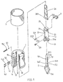
- This cylinder lock includes a cylindrical barrel 1, a cylinder 2 rotatably mounted in barrel 1, a housing 3 mounted around barrel 1, an actuating member 26 and a key 5 adapted to be inserted into cylinder 2.
- Barrel 1 has a longitudinal central bore 11, an annular flange 12 formed at the front end of barrel 1, an annular recess 13 located in the inner wall at the front end of barrel 1, and a plurality of radial bores 14 formed in the wall of barrel 1 and spaced longitudinally in relation to each other. The number and spacing of radial bores 14 is to be determined as desired.
- an upper tumbler 141 and a spring 142 are provided in each radial bore 14.
- another radial bore 15 is provided.
- Radial bore 15 is mounted with a ball 151 and a spring 152 to constitute a positioning device which will be described later.
- Cylinder 2 has a longitudinal circular key-hole 21 for receiving round key 5.
- Cylinder 2 has an annular flange 21a formed at its front end and adapted to be received in annular recess 13, thereby allowing the front surface of flange 21a to be flush with the front surface of annular flange 12 when cylinder 2 is mounted in bore 11 of barrel 1.
- a plurality of radial stepped bores 22 are provided which correspond to radial bores 14 of barrel 1.
- a lower tumbler 221 is mounted in each radial bore 22 with its pin portion 2212 extending into keyhole 21 by the biasing force of spring 142.
- Cylinder 2 is further provided with an annular groove 23 around its rear end portion which extends beyond the rear end surface of barrel 1 when cylinder 2 is mounted therein, and a slot 25 formed in the rear end thereof and extending perpendicularly to the rear end surface of cylinder 2 to a depth beyond groove 23.
- Actuating member 26 having fork ends 261, 262 is detachably mounted in slot 25 by means of a snap ring 4 engaged in annular groove 23. The other end of actuating member 26 is operatively connected to a lock bolt (not shown).
- An indent 24 is provided on the outer wall of cylinder 2 adjacent to the last radial bore 22 to correspond with radial bore 15 of barrel 1.
- Indent 24 has a dimension such that ball 151 may be partly received therein when cylinder 2 is rotated to a predetermined position where its radial bores 22 are in alignment with radial bores 14, but which allowing ball 151 to escape therefrom when cylinder 2 is rotated past that predetermined position. In this way, indent 24 forms a positioning device together with ball 151 and spring 152.
- Housing 3 is sleeved onto barrel 1 to maintain upper tumblers 141 and springs 142 within corresponding radial bores 14.
- an annular indent 31 (Fig. 4) in the outer wall of housing 3 may be provided by press forming at a position corresponding to radial bore 15.
- Key 5 has a bow 5a and a round shaft 51 extending from bow 5a.
- Shaft 51 has a conical end to facilitate the insertion of key 5 into keyhole 21 of cylinder 2.
- Shaft 51 has its one side surface preferably extending from bow 5a, flattened to form a planar surface 512 in which a plurality of recesses 52 is provided.
- Recesses 52 correspond respectively to lower tumblers 221 so that when key 5 is inserted into keyhole 21 and turned, lower tumblers 221 will be raised to a position in which all upper and lower tumblers 141 and 221 are so situated that there is no impediment between the barrel 1 and cylinder 2 to restrict the rotation of cylinder 2 relative to barrel 1 when key 5 is further turned.
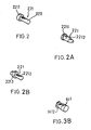
- lower tumbler 221 is so configured as to have a circular head 2211 and a round pin portion 2212 extending from head 2211.
- the top surface of head 2211 and the end surface of pin portion 2212 are both rounded.
- Pin portion 2212 may have its extreme end to be formed into a conical shape, as shown in Fig. 2A.
- Lower tumbler 221 may also have an annular flange 2213 formed along the intermediate part of pin portion 2212, as shown in Fig. 2B.
- upper tumblers 141 may also have various configurations. For example, as shown in Fig. 3, upper tumbler 141 is formed into a round pin with planar end surfaces.
- Pin tumbler 141 may further be formed with a flat round head 1411 at its opposite ends, as shown in Fig. 3A.
- pin tumbler 41 may also be formed into a substantially solid cup-shaped configuration, as viewed perpendicularly to the elevation thereof, to have a conical portion 1412 extending between its opposite ends, as shown in Fig. 3B. These configurations help to prevent the picking of the lock.
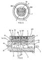
- the cylinder lock of this invention is normally in a locked state in which cylinder 2 is impeded from turning relative to barrel 1 as upper tumblers 141 biased by springs 142 cross the parting line between barrel 1 and cylinder 2.
- lower tumblers 221 will first be raised a predetermined amount and, pushed by the biasing force of springs 142, to cause their pin portions 2212 to move into the corresponding recesses 52, so that the lower ends of upper tumblers 141 are flush with the parting line, as shown in Fig. 6.
- Cylinder 2 can therefore rotate relative to barrel 1 to unlock or lock the lock device when key 5 is further rotated, as pin portions 2212 are in close contact with side walls 543 or 543' of recesses 52.
Landscapes
- Lock And Its Accessories (AREA)
- Vehicle Body Suspensions (AREA)
- Chairs Characterized By Structure (AREA)
- Valve Device For Special Equipments (AREA)
Priority Applications (6)
| Application Number | Priority Date | Filing Date | Title |
|---|---|---|---|
| US07/859,202 US5247818A (en) | 1992-03-27 | 1992-03-27 | Cylinder lock |
| EP92303043A EP0708217B1 (fr) | 1992-03-27 | 1992-04-07 | Serrure cylindrique |
| DE69228327T DE69228327T2 (de) | 1992-03-27 | 1992-04-07 | Zylinderschloss |
| ES92303043T ES2129428T3 (es) | 1992-03-27 | 1992-04-07 | Cerradura de cilindro. |
| AT92303043T ATE176293T1 (de) | 1992-03-27 | 1992-04-07 | Zylinderschloss |
| GR990401059T GR3029980T3 (en) | 1992-03-27 | 1999-04-16 | Cylinder lock |
Applications Claiming Priority (2)
| Application Number | Priority Date | Filing Date | Title |
|---|---|---|---|
| US07/859,202 US5247818A (en) | 1992-03-27 | 1992-03-27 | Cylinder lock |
| EP92303043A EP0708217B1 (fr) | 1992-03-27 | 1992-04-07 | Serrure cylindrique |
Publications (2)
| Publication Number | Publication Date |
|---|---|
| EP0708217A1 true EP0708217A1 (fr) | 1996-04-24 |
| EP0708217B1 EP0708217B1 (fr) | 1999-01-27 |
Family
ID=26131994
Family Applications (1)
| Application Number | Title | Priority Date | Filing Date |
|---|---|---|---|
| EP92303043A Expired - Lifetime EP0708217B1 (fr) | 1992-03-27 | 1992-04-07 | Serrure cylindrique |
Country Status (6)
| Country | Link |
|---|---|
| US (1) | US5247818A (fr) |
| EP (1) | EP0708217B1 (fr) |
| AT (1) | ATE176293T1 (fr) |
| DE (1) | DE69228327T2 (fr) |
| ES (1) | ES2129428T3 (fr) |
| GR (1) | GR3029980T3 (fr) |
Cited By (1)
| Publication number | Priority date | Publication date | Assignee | Title |
|---|---|---|---|---|
| DE102007000177A1 (de) * | 2007-03-27 | 2008-10-02 | Aug. Winkhaus Gmbh & Co. Kg | Schließzylinder |
Families Citing this family (10)
| Publication number | Priority date | Publication date | Assignee | Title |
|---|---|---|---|---|
| FI108308B (fi) * | 1998-09-25 | 2001-12-31 | Abloy Oy | Sylinterilukko-avain-yhdistelmä |
| US6983630B2 (en) * | 2003-07-09 | 2006-01-10 | Kaba Ilco Corp. | Programmable cylinder lock system |
| US7028517B2 (en) * | 2003-07-09 | 2006-04-18 | Kaba High Security Locks Corporation | Cylinder lock with programmable keyway |
| DE102004013522A1 (de) * | 2004-03-19 | 2005-10-06 | Aug. Winkhaus Gmbh & Co. Kg | Schlüssel |
| US20080110220A1 (en) * | 2006-11-10 | 2008-05-15 | Talleres De Escoriaza S.A. | Security device for lock cylinders |
| US8438889B2 (en) * | 2007-02-22 | 2013-05-14 | Sargent Maufacturing Company | Shaped top pin for bump resistant cylinder |
| CN101377102A (zh) * | 2007-08-31 | 2009-03-04 | 新辉兴业有限公司 | 防盗弹子结构锁 |
| US20130192320A1 (en) * | 2012-01-26 | 2013-08-01 | Compx International Inc. | Lock system |
| CN104919122A (zh) * | 2012-12-04 | 2015-09-16 | 品谱股份有限公司 | 利用扭矩阻力的防撬锁芯 |
| US9376837B2 (en) | 2014-11-11 | 2016-06-28 | Neil D. Koelker | Multisided key and lock |
Citations (5)
| Publication number | Priority date | Publication date | Assignee | Title |
|---|---|---|---|---|
| US2093925A (en) * | 1936-05-18 | 1937-09-21 | New Haven Vibrator Company Inc | Cylinder lock |
| FR2514810A1 (fr) * | 1981-10-15 | 1983-04-22 | Lo Jiuan | Serrure inviolable a corps cylindrique et fourreau dormant avec cle a tige cylindrique |
| GB2184155A (en) * | 1985-11-19 | 1987-06-17 | Jack William Taylor | A lock key |
| GB2216943A (en) * | 1988-04-07 | 1989-10-18 | Gibbons Of Willenhall Limited | Cylinder lock |
| US5042330A (en) * | 1990-06-15 | 1991-08-27 | Lo Jian P | Key manufacturing method |
Family Cites Families (14)
| Publication number | Priority date | Publication date | Assignee | Title |
|---|---|---|---|---|
| US18169A (en) * | 1857-09-08 | Padlock | ||
| US31278A (en) * | 1861-01-29 | Linus yale | ||
| USRE26272E (en) * | 1967-09-26 | Locking mechanisms | ||
| US183047A (en) * | 1876-10-10 | Improvement in locks for doors | ||
| US913942A (en) * | 1907-12-21 | 1909-03-02 | John W Bodge | Lock. |
| US1514318A (en) * | 1919-05-29 | 1924-11-04 | Josef Herman Nordqvist | Safety lock |
| US1635724A (en) * | 1924-04-03 | 1927-07-12 | Morris Archibald William | Lock |
| US2439099A (en) * | 1945-11-16 | 1948-04-06 | Nicholas J Ressetar | Guard device for lock mechanism |
| FR993427A (fr) * | 1949-06-20 | 1951-10-31 | Serrure de sûreté | |
| US3681953A (en) * | 1969-02-07 | 1972-08-08 | James C Luttrall | Lock and method of production therefor |
| US3637180A (en) * | 1970-08-19 | 1972-01-25 | Robert D Parry | Wall mount device for guns |
| US3780549A (en) * | 1971-09-08 | 1973-12-25 | Schlage Lock Co | Binary multi-plane cylinder |
| CH591618A5 (fr) * | 1975-09-11 | 1977-09-30 | Bauer Kaba Ag | |
| US4193277A (en) * | 1978-02-08 | 1980-03-18 | Lo Jiuan P | Lock body with locking pins opened or closed by the cylindrical key bar |
-
1992
- 1992-03-27 US US07/859,202 patent/US5247818A/en not_active Expired - Fee Related
- 1992-04-07 EP EP92303043A patent/EP0708217B1/fr not_active Expired - Lifetime
- 1992-04-07 ES ES92303043T patent/ES2129428T3/es not_active Expired - Lifetime
- 1992-04-07 DE DE69228327T patent/DE69228327T2/de not_active Expired - Fee Related
- 1992-04-07 AT AT92303043T patent/ATE176293T1/de active
-
1999
- 1999-04-16 GR GR990401059T patent/GR3029980T3/el unknown
Patent Citations (5)
| Publication number | Priority date | Publication date | Assignee | Title |
|---|---|---|---|---|
| US2093925A (en) * | 1936-05-18 | 1937-09-21 | New Haven Vibrator Company Inc | Cylinder lock |
| FR2514810A1 (fr) * | 1981-10-15 | 1983-04-22 | Lo Jiuan | Serrure inviolable a corps cylindrique et fourreau dormant avec cle a tige cylindrique |
| GB2184155A (en) * | 1985-11-19 | 1987-06-17 | Jack William Taylor | A lock key |
| GB2216943A (en) * | 1988-04-07 | 1989-10-18 | Gibbons Of Willenhall Limited | Cylinder lock |
| US5042330A (en) * | 1990-06-15 | 1991-08-27 | Lo Jian P | Key manufacturing method |
Cited By (1)
| Publication number | Priority date | Publication date | Assignee | Title |
|---|---|---|---|---|
| DE102007000177A1 (de) * | 2007-03-27 | 2008-10-02 | Aug. Winkhaus Gmbh & Co. Kg | Schließzylinder |
Also Published As
| Publication number | Publication date |
|---|---|
| EP0708217B1 (fr) | 1999-01-27 |
| GR3029980T3 (en) | 1999-07-30 |
| DE69228327T2 (de) | 1999-09-09 |
| ES2129428T3 (es) | 1999-06-16 |
| DE69228327D1 (de) | 1999-03-11 |
| ATE176293T1 (de) | 1999-02-15 |
| US5247818A (en) | 1993-09-28 |
Similar Documents
| Publication | Publication Date | Title |
|---|---|---|
| US5899099A (en) | Combination lock | |
| US5934120A (en) | Lock with a resettable combination | |
| EP0708217B1 (fr) | Serrure cylindrique | |
| JP2905381B2 (ja) | キーブランク及びキー | |
| US5222383A (en) | Cylinder lock | |
| US6389857B1 (en) | Push-button steering wheel lock | |
| US4858455A (en) | Lock core | |
| US6758073B2 (en) | Lock assembly | |
| US7131299B1 (en) | Combination lock and padlock combination with opening warning device | |
| CA2074927C (fr) | Verrou a entree de cle incurvee | |
| US5832762A (en) | U-lock keyway protector | |
| EP0927802A1 (fr) | Dispositif de verrouillage | |
| US5433092A (en) | Cuff lock | |
| GB2228763A (en) | Combination lock | |
| WO2000014365A1 (fr) | Serrure a debrayage automatique | |
| US4866964A (en) | Removable core lock | |
| US6634197B2 (en) | Lock device with removable core | |
| AU614398B2 (en) | Push-button padlocks having swivel-only shackles | |
| US4193276A (en) | Lock for railroad switch | |
| CN100402786C (zh) | 改进的钥匙和锁 | |
| US4193277A (en) | Lock body with locking pins opened or closed by the cylindrical key bar | |
| US4454735A (en) | Screw lock | |
| US5511400A (en) | Lock mechanism for use in a securing device | |
| US5046342A (en) | Cylinder lock | |
| AU1591800A (en) | A locking device for weapons |
Legal Events
| Date | Code | Title | Description |
|---|---|---|---|
| PUAI | Public reference made under article 153(3) epc to a published international application that has entered the european phase |
Free format text: ORIGINAL CODE: 0009012 |
|
| 17P | Request for examination filed |
Effective date: 19931229 |
|
| AK | Designated contracting states |
Kind code of ref document: A1 Designated state(s): AT BE CH DE DK ES FR GB GR IT LI LU MC NL PT SE |
|
| 17Q | First examination report despatched |
Effective date: 19970429 |
|
| GRAG | Despatch of communication of intention to grant |
Free format text: ORIGINAL CODE: EPIDOS AGRA |
|
| GRAG | Despatch of communication of intention to grant |
Free format text: ORIGINAL CODE: EPIDOS AGRA |
|
| GRAH | Despatch of communication of intention to grant a patent |
Free format text: ORIGINAL CODE: EPIDOS IGRA |
|
| GRAH | Despatch of communication of intention to grant a patent |
Free format text: ORIGINAL CODE: EPIDOS IGRA |
|
| GRAA | (expected) grant |
Free format text: ORIGINAL CODE: 0009210 |
|
| AK | Designated contracting states |
Kind code of ref document: B1 Designated state(s): AT BE CH DE DK ES FR GB GR IT LI LU MC NL PT SE |
|
| PG25 | Lapsed in a contracting state [announced via postgrant information from national office to epo] |
Ref country code: AT Free format text: LAPSE BECAUSE OF FAILURE TO SUBMIT A TRANSLATION OF THE DESCRIPTION OR TO PAY THE FEE WITHIN THE PRESCRIBED TIME-LIMIT Effective date: 19990127 |
|
| REF | Corresponds to: |
Ref document number: 176293 Country of ref document: AT Date of ref document: 19990215 Kind code of ref document: T |
|
| REG | Reference to a national code |
Ref country code: CH Ref legal event code: EP |
|
| REF | Corresponds to: |
Ref document number: 69228327 Country of ref document: DE Date of ref document: 19990311 |
|
| PG25 | Lapsed in a contracting state [announced via postgrant information from national office to epo] |
Ref country code: LU Free format text: LAPSE BECAUSE OF NON-PAYMENT OF DUE FEES Effective date: 19990407 |
|
| ITF | It: translation for a ep patent filed | ||
| PG25 | Lapsed in a contracting state [announced via postgrant information from national office to epo] |
Ref country code: DK Free format text: LAPSE BECAUSE OF FAILURE TO SUBMIT A TRANSLATION OF THE DESCRIPTION OR TO PAY THE FEE WITHIN THE PRESCRIBED TIME-LIMIT Effective date: 19990427 |
|
| ET | Fr: translation filed | ||
| REG | Reference to a national code |
Ref country code: CH Ref legal event code: NV Representative=s name: KEMENY AG PATENTANWALTBUERO |
|
| REG | Reference to a national code |
Ref country code: PT Ref legal event code: SC4A Free format text: AVAILABILITY OF NATIONAL TRANSLATION Effective date: 19990426 |
|
| PG25 | Lapsed in a contracting state [announced via postgrant information from national office to epo] |
Ref country code: MC Free format text: LAPSE BECAUSE OF NON-PAYMENT OF DUE FEES Effective date: 19991031 |
|
| PLBE | No opposition filed within time limit |
Free format text: ORIGINAL CODE: 0009261 |
|
| STAA | Information on the status of an ep patent application or granted ep patent |
Free format text: STATUS: NO OPPOSITION FILED WITHIN TIME LIMIT |
|
| 26N | No opposition filed | ||
| REG | Reference to a national code |
Ref country code: GB Ref legal event code: IF02 |
|
| PGFP | Annual fee paid to national office [announced via postgrant information from national office to epo] |
Ref country code: GB Payment date: 20020403 Year of fee payment: 11 |
|
| PGFP | Annual fee paid to national office [announced via postgrant information from national office to epo] |
Ref country code: PT Payment date: 20020405 Year of fee payment: 11 Ref country code: FR Payment date: 20020405 Year of fee payment: 11 |
|
| PGFP | Annual fee paid to national office [announced via postgrant information from national office to epo] |
Ref country code: GR Payment date: 20020408 Year of fee payment: 11 |
|
| PGFP | Annual fee paid to national office [announced via postgrant information from national office to epo] |
Ref country code: SE Payment date: 20020410 Year of fee payment: 11 Ref country code: BE Payment date: 20020410 Year of fee payment: 11 |
|
| PGFP | Annual fee paid to national office [announced via postgrant information from national office to epo] |
Ref country code: ES Payment date: 20020418 Year of fee payment: 11 |
|
| PGFP | Annual fee paid to national office [announced via postgrant information from national office to epo] |
Ref country code: CH Payment date: 20020424 Year of fee payment: 11 |
|
| PGFP | Annual fee paid to national office [announced via postgrant information from national office to epo] |
Ref country code: NL Payment date: 20020430 Year of fee payment: 11 |
|
| PGFP | Annual fee paid to national office [announced via postgrant information from national office to epo] |
Ref country code: DE Payment date: 20020506 Year of fee payment: 11 |
|
| PG25 | Lapsed in a contracting state [announced via postgrant information from national office to epo] |
Ref country code: GB Free format text: LAPSE BECAUSE OF NON-PAYMENT OF DUE FEES Effective date: 20030407 |
|
| PG25 | Lapsed in a contracting state [announced via postgrant information from national office to epo] |
Ref country code: SE Free format text: LAPSE BECAUSE OF NON-PAYMENT OF DUE FEES Effective date: 20030408 Ref country code: ES Free format text: LAPSE BECAUSE OF NON-PAYMENT OF DUE FEES Effective date: 20030408 |
|
| PG25 | Lapsed in a contracting state [announced via postgrant information from national office to epo] |
Ref country code: LI Free format text: LAPSE BECAUSE OF NON-PAYMENT OF DUE FEES Effective date: 20030430 Ref country code: CH Free format text: LAPSE BECAUSE OF NON-PAYMENT OF DUE FEES Effective date: 20030430 Ref country code: BE Free format text: LAPSE BECAUSE OF NON-PAYMENT OF DUE FEES Effective date: 20030430 |
|
| BERE | Be: lapsed |
Owner name: *LO JIUAN PENG Effective date: 20030430 |
|
| PG25 | Lapsed in a contracting state [announced via postgrant information from national office to epo] |
Ref country code: PT Free format text: LAPSE BECAUSE OF NON-PAYMENT OF DUE FEES Effective date: 20031031 |
|
| PG25 | Lapsed in a contracting state [announced via postgrant information from national office to epo] |
Ref country code: NL Free format text: LAPSE BECAUSE OF NON-PAYMENT OF DUE FEES Effective date: 20031101 Ref country code: DE Free format text: LAPSE BECAUSE OF NON-PAYMENT OF DUE FEES Effective date: 20031101 |
|
| PG25 | Lapsed in a contracting state [announced via postgrant information from national office to epo] |
Ref country code: GR Free format text: LAPSE BECAUSE OF NON-PAYMENT OF DUE FEES Effective date: 20031104 |
|
| GBPC | Gb: european patent ceased through non-payment of renewal fee |
Effective date: 20030407 |
|
| NLV4 | Nl: lapsed or anulled due to non-payment of the annual fee |
Effective date: 20031101 |
|
| EUG | Se: european patent has lapsed | ||
| REG | Reference to a national code |
Ref country code: CH Ref legal event code: PL |
|
| PG25 | Lapsed in a contracting state [announced via postgrant information from national office to epo] |
Ref country code: FR Free format text: LAPSE BECAUSE OF NON-PAYMENT OF DUE FEES Effective date: 20031231 |
|
| REG | Reference to a national code |
Ref country code: FR Ref legal event code: ST Ref country code: PT Ref legal event code: MM4A Free format text: LAPSE DUE TO NON-PAYMENT OF FEES Effective date: 20031031 |
|
| REG | Reference to a national code |
Ref country code: ES Ref legal event code: FD2A Effective date: 20030408 |
|
| PG25 | Lapsed in a contracting state [announced via postgrant information from national office to epo] |
Ref country code: IT Free format text: LAPSE BECAUSE OF NON-PAYMENT OF DUE FEES Effective date: 20050407 |