EP0708226A2 - Bremse für Hebevorrichtung - Google Patents
Bremse für Hebevorrichtung Download PDFInfo
- Publication number
- EP0708226A2 EP0708226A2 EP95850173A EP95850173A EP0708226A2 EP 0708226 A2 EP0708226 A2 EP 0708226A2 EP 95850173 A EP95850173 A EP 95850173A EP 95850173 A EP95850173 A EP 95850173A EP 0708226 A2 EP0708226 A2 EP 0708226A2
- Authority
- EP
- European Patent Office
- Prior art keywords
- brake
- hydraulic
- mechanical
- hoisting
- braking power
- Prior art date
- Legal status (The legal status is an assumption and is not a legal conclusion. Google has not performed a legal analysis and makes no representation as to the accuracy of the status listed.)
- Withdrawn
Links
- 230000005540 biological transmission Effects 0.000 claims abstract description 11
- 230000000694 effects Effects 0.000 claims description 7
- 238000006073 displacement reaction Methods 0.000 claims description 5
- 230000008878 coupling Effects 0.000 claims description 4
- 238000010168 coupling process Methods 0.000 claims description 4
- 238000005859 coupling reaction Methods 0.000 claims description 4
- 239000012530 fluid Substances 0.000 claims 3
- 230000001276 controlling effect Effects 0.000 description 6
- 230000006698 induction Effects 0.000 description 6
- 238000005553 drilling Methods 0.000 description 5
- 230000001105 regulatory effect Effects 0.000 description 2
- 230000033228 biological regulation Effects 0.000 description 1
- 239000000314 lubricant Substances 0.000 description 1
- 230000009467 reduction Effects 0.000 description 1
- 230000000717 retained effect Effects 0.000 description 1
- 230000000007 visual effect Effects 0.000 description 1
Images


Classifications
-
- E—FIXED CONSTRUCTIONS
- E21—EARTH OR ROCK DRILLING; MINING
- E21B—EARTH OR ROCK DRILLING; OBTAINING OIL, GAS, WATER, SOLUBLE OR MELTABLE MATERIALS OR A SLURRY OF MINERALS FROM WELLS
- E21B44/00—Automatic control systems specially adapted for drilling operations, i.e. self-operating systems which function to carry out or modify a drilling operation without intervention of a human operator, e.g. computer-controlled drilling systems; Systems specially adapted for monitoring a plurality of drilling variables or conditions
- E21B44/02—Automatic control of the tool feed
-
- B—PERFORMING OPERATIONS; TRANSPORTING
- B60—VEHICLES IN GENERAL
- B60T—VEHICLE BRAKE CONTROL SYSTEMS OR PARTS THEREOF; BRAKE CONTROL SYSTEMS OR PARTS THEREOF, IN GENERAL; ARRANGEMENT OF BRAKING ELEMENTS ON VEHICLES IN GENERAL; PORTABLE DEVICES FOR PREVENTING UNWANTED MOVEMENT OF VEHICLES; VEHICLE MODIFICATIONS TO FACILITATE COOLING OF BRAKES
- B60T13/00—Transmitting braking action from initiating means to ultimate brake actuator with power assistance or drive; Brake systems incorporating such transmitting means, e.g. air-pressure brake systems
- B60T13/10—Transmitting braking action from initiating means to ultimate brake actuator with power assistance or drive; Brake systems incorporating such transmitting means, e.g. air-pressure brake systems with fluid assistance, drive, or release
- B60T13/58—Combined or convertible systems
- B60T13/585—Combined or convertible systems comprising friction brakes and retarders
-
- B—PERFORMING OPERATIONS; TRANSPORTING
- B66—HOISTING; LIFTING; HAULING
- B66D—CAPSTANS; WINCHES; TACKLES, e.g. PULLEY BLOCKS; HOISTS
- B66D5/00—Braking or detent devices characterised by application to lifting or hoisting gear, e.g. for controlling the lowering of loads
- B66D5/02—Crane, lift hoist, or winch brakes operating on drums, barrels, or ropes
- B66D5/24—Operating devices
-
- E—FIXED CONSTRUCTIONS
- E21—EARTH OR ROCK DRILLING; MINING
- E21B—EARTH OR ROCK DRILLING; OBTAINING OIL, GAS, WATER, SOLUBLE OR MELTABLE MATERIALS OR A SLURRY OF MINERALS FROM WELLS
- E21B19/00—Handling rods, casings, tubes or the like outside the borehole, e.g. in the derrick; Apparatus for feeding the rods or cables
- E21B19/008—Winding units, specially adapted for drilling operations
Definitions
- the present invention relates to a brake for a hoisting apparatus according to the preamble to claim 1.
- a conventional hoisting apparatus comprises at least one mechanical brake system which is manually controlled.
- the hoisting apparatus can also be equipped with a hydraulic brake or an electrical brake, usually of the induction brake type (eddy current brake), in order to relieve the mechanical brake at high cable speed.
- US 2,159,250 and US 2,563,089 show examples of such hoisting apparatuses having two independent brakes.
- a brake system comprising a dynamic brake characterized by the features which appear in the characterizing clause of the present claim 1.
- the dynamic brake can in a simple manner be installed in an already existing hoisting apparatus having a mechanical brake and possibly a hydraulic brake or an induction brake.
- the hydraulic brake or induction brake is removed, and the dynamic brake is mounted on the drum shaft where the previous brake was placed.
- the mechanical brake may be retained as an emergency brake, its removal being unnecessary for achieving the desired effect, but it will normally not be used since the dynamic brake possesses sufficient braking effect to stop the drum also in an emergency.
- the hydraulic brake can also be provided with a so-called autodriller.
- This consists of, inter alia, a hydraulic motor adapted to wind and unwind the hoisting cable by small rotations of the drum in one direction or the other.
- the autodriller is used to control the weight on the bit.
- the other parts of the brake system are disconnected when the autodriller is in operation.
- the autodriller is automatically regulated by a separate control system or, preferably, by the same control system that regulates the dynamic brake, in accordance with the weight of the drill string or other parameters of importance in order to attain the desired weight on the drill string.
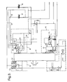
- FIG. 1 there is shown a hoisting apparatus of conventional type, provided with a control console 2 for an operator controlling the braking action of the hoisting apparatus.
- the conventional hoisting apparatus 1 is equipped with an induction brake 3 (indicated by dotted lines) which is used together with a mechanical brake for controlling the lowering action of the hoisting apparatus.
- the operating console 2 comprises a plurality of operating means for controlling the hoisting apparatus.
- the induction brake 3 is replaced by a dynamic brake system 4 which is operated via a control unit 5 by an operator 6 who is preferably located in a cabin 7 with a view of the hoisting apparatus 1.
- the hydraulic brake 4 consists of a hydraulic brake 8 and a mechanical brake 9.
- the unit 4 also comprises an autodriller 10 for automatic adjustment of the weight on the bit and precision control of the raising and lowering action. From the dynamic brake there extends a shaft 11, connected to the hoisting drum.
- the operator 6 can in a simple way control both the releasing and retracting of the hoisting cable by the use of operating means, for example a so-called "joy-stick,” which can be coupled both to the braking function of the hoisting apparatus and to the motor which retracts the hoisting cable, so that actuating the operating means in one direction effects a controlled lowering, and actuating the means in the other direction effects a lifting movement.
- operating means for example a so-called "joy-stick”
- the mechanical brake 9 which is preferably a multi-plate brake, is prestressed by means of springs 12 for an on-position, so that the brake is automatically actuated if the hydraulic pressure disappears.
- hydraulic pressure is introduced from a feed line 13 through a two-way control valve 14 supplied from the existing main hydraulic system.
- the mechanical brake is cooled with oil.
- the hydraulic brake consists of a hydraulic pump 15 which also is supplied from the existing main hydraulic system via a line 16 through a two-way control valve 17.
- the hydraulic pressure applied via line 16 regulates the displacement of the hydraulic pump 15.
- a pressure-controlled valve 20 which provides a counter pressure on the pressure side of the pump is mounted in the ring line 19.
- the bearings of the pump 15 are provided with lubricant via a throttled line 22.
- Warm oil heated because of the high pressure from the braking action, is continuously discharged from the pump and ring line 19 via a discharge line 23 and a prestressed check valve leading back to the return line.
- the ring line 19 is continuously supplied with oil from the pressure side of the hydraulic system via a line 24 having an excess pressure of about 10 bar.
- the two control valves 14 and 17 are operated via the control system 5, providing automatic regulation of the braking effect of the two brake systems.
- the autodriller 10 consists of a motor 34 regulated via a three-way valve 35.
- the motor 34 is connected to the drum via a gear having a high gear ratio.
- the pump 34 is coupled to the drum by operating a coupling 36.
- the brakes 8 and 9 are then disconnected in that the pump 15 is positioned at zero displacement and the plates of the mechanical brake 9 are lifted out of the braking position.
- the motor 34 now drives the drill string up and down in small movements depending upon the weight on the drill bit.
- the motor 34 can be used for raising and lowering the drill string and for achieving accurate operation of the hoisting apparatus, for example in order to carry out a precision coupling.
- the system comprises all the other components which are necessary for any type of hydraulic system, such as hydraulic pumps for generating pressure in the system, return tank, filters, coolers, expansion tank, etc.
- the dynamic brake is shown as it appears in reality, with a number of mechanical friction brakes 29 positioned on one side of the transmission 30 and a number of hydraulic pumps 31 positioned on the other side of the transmission 30.
- the autodriller is designated by the reference numeral 32.
- a shaft 33 leads to the hoisting drum.
- the dynamic brake 4 can thus be mounted as a unit on the hoisting apparatus, possibly replacing a conventional induction brake.
- the present invention provides a braking system constituting one unit that in a simple manner can be mounted on an existing hoisting apparatus.
- the braking system gives unique possibilities for controlling, in a simple manner, the lowering operation.
- the dynamic brake constitutes, together with an appropriate control system, a complete system for lowering the drill string and controlling the weight on the bit.
Landscapes
- Engineering & Computer Science (AREA)
- Life Sciences & Earth Sciences (AREA)
- Geology (AREA)
- Mining & Mineral Resources (AREA)
- Mechanical Engineering (AREA)
- Physics & Mathematics (AREA)
- Environmental & Geological Engineering (AREA)
- Fluid Mechanics (AREA)
- General Life Sciences & Earth Sciences (AREA)
- Geochemistry & Mineralogy (AREA)
- Transportation (AREA)
- Braking Arrangements (AREA)
Applications Claiming Priority (2)
| Application Number | Priority Date | Filing Date | Title |
|---|---|---|---|
| NO943731 | 1994-10-05 | ||
| NO943731A NO306814B1 (no) | 1994-10-05 | 1994-10-05 | Brems for heisespill |
Publications (2)
| Publication Number | Publication Date |
|---|---|
| EP0708226A2 true EP0708226A2 (de) | 1996-04-24 |
| EP0708226A3 EP0708226A3 (de) | 1998-01-07 |
Family
ID=19897474
Family Applications (1)
| Application Number | Title | Priority Date | Filing Date |
|---|---|---|---|
| EP95850173A Withdrawn EP0708226A3 (de) | 1994-10-05 | 1995-10-03 | Bremse für Hebevorrichtung |
Country Status (3)
| Country | Link |
|---|---|
| US (1) | US5709285A (de) |
| EP (1) | EP0708226A3 (de) |
| NO (1) | NO306814B1 (de) |
Cited By (4)
| Publication number | Priority date | Publication date | Assignee | Title |
|---|---|---|---|---|
| GB2325207A (en) * | 1997-05-06 | 1998-11-18 | Eaton Corp | Winch control |
| WO2003072904A1 (de) * | 2002-02-27 | 2003-09-04 | Wirth Maschinen- und Bohrgeräte-Fabrik GmbH | Hebewerk |
| WO2013082584A1 (en) * | 2011-12-02 | 2013-06-06 | Schlumberger Canada Limited | Quick drum connect |
| CN115853933A (zh) * | 2022-10-11 | 2023-03-28 | 山东科技大学 | 一种制动器用热备双回路控制系统及方法 |
Families Citing this family (5)
| Publication number | Priority date | Publication date | Assignee | Title |
|---|---|---|---|---|
| US7026950B2 (en) * | 2003-03-12 | 2006-04-11 | Varco I/P, Inc. | Motor pulse controller |
| US7059427B2 (en) * | 2003-04-01 | 2006-06-13 | Noble Drilling Services Inc. | Automatic drilling system |
| CN103011003A (zh) * | 2012-12-17 | 2013-04-03 | 杨恩峰 | 双控制薄膜式钻机气控刹车控制方法及系统 |
| CN103277042B (zh) * | 2013-06-04 | 2015-10-28 | 上海中联重科桩工机械有限公司 | 钻机动力头的液压控制系统和钻机 |
| US11807493B1 (en) | 2018-10-15 | 2023-11-07 | Otis Elevator Company | Retrofitted hoist machine |
Citations (2)
| Publication number | Priority date | Publication date | Assignee | Title |
|---|---|---|---|---|
| US2159250A (en) | 1937-11-10 | 1939-05-23 | John E Brantly | Oil well hoist |
| US2563089A (en) | 1946-06-07 | 1951-08-07 | Wilson John Hart | Winch |
Family Cites Families (13)
| Publication number | Priority date | Publication date | Assignee | Title |
|---|---|---|---|---|
| US1746371A (en) * | 1926-11-30 | 1930-02-11 | Goodyear Tire & Rubber | Method of preserving rubber |
| US1992911A (en) * | 1932-03-26 | 1935-02-26 | Parkersburg Rig & Reel Co | Hydrodynamic brake for hoists and the like |
| US1992912A (en) * | 1933-06-07 | 1935-02-26 | Parkersburg Rig & Reel Co | Brake system for drilling equipment |
| US2883013A (en) * | 1954-10-25 | 1959-04-21 | Keith | Fluid coupled load braking apparatus |
| US4207969A (en) * | 1974-01-14 | 1980-06-17 | Robert Howell Industries | Wet disc friction device |
| US4043434A (en) * | 1974-08-29 | 1977-08-23 | Parmac, Inc. | Mechanically adjustable dual pocket hydromatic brake |
| US4324387A (en) * | 1980-01-30 | 1982-04-13 | Twin Disc, Incorporated | Power delivery system having a pressure modulated hydrodynamic retarder for controlling a load |
| GB2195157B (en) * | 1984-03-29 | 1989-09-06 | Armco Inc | Improvement in or relating to methods of braking rotating drums |
| US4542944A (en) * | 1984-04-12 | 1985-09-24 | American Standard Inc. | Multiple disk brake control |
| SU1344733A1 (ru) * | 1985-08-16 | 1987-10-15 | Уральский политехнический институт им.С.М.Кирова | Способ управлени предохранительным торможением кранового механизма с фрикционным тормозом |
| US4875530A (en) * | 1987-09-24 | 1989-10-24 | Parker Technology, Inc. | Automatic drilling system |
| DE3809646A1 (de) * | 1988-03-22 | 1989-10-05 | Delmag Maschinenfabrik | Freifall-steuereinrichtung |
| AU7728394A (en) * | 1993-09-15 | 1995-04-03 | Gregory Rig Service & Sales, Inc. | Brake system for drilling equipment |
-
1994
- 1994-10-05 NO NO943731A patent/NO306814B1/no not_active IP Right Cessation
-
1995
- 1995-10-03 US US08/538,218 patent/US5709285A/en not_active Expired - Fee Related
- 1995-10-03 EP EP95850173A patent/EP0708226A3/de not_active Withdrawn
Patent Citations (2)
| Publication number | Priority date | Publication date | Assignee | Title |
|---|---|---|---|---|
| US2159250A (en) | 1937-11-10 | 1939-05-23 | John E Brantly | Oil well hoist |
| US2563089A (en) | 1946-06-07 | 1951-08-07 | Wilson John Hart | Winch |
Cited By (8)
| Publication number | Priority date | Publication date | Assignee | Title |
|---|---|---|---|---|
| GB2325207A (en) * | 1997-05-06 | 1998-11-18 | Eaton Corp | Winch control |
| GB2325207B (en) * | 1997-05-06 | 2000-09-27 | Eaton Corp | Force transmitting apparatus |
| WO2003072904A1 (de) * | 2002-02-27 | 2003-09-04 | Wirth Maschinen- und Bohrgeräte-Fabrik GmbH | Hebewerk |
| US7232113B2 (en) | 2002-02-27 | 2007-06-19 | Wirth Maschinen- und Bohrgeräte-Fabrik GmbH | Draw works |
| CN1325752C (zh) * | 2002-02-27 | 2007-07-11 | 维尔特机器和钻孔工具制造厂有限公司 | 提升装置 |
| NO330088B1 (no) * | 2002-02-27 | 2011-02-14 | Aker Wirth Gmbh | Borevinsj |
| WO2013082584A1 (en) * | 2011-12-02 | 2013-06-06 | Schlumberger Canada Limited | Quick drum connect |
| CN115853933A (zh) * | 2022-10-11 | 2023-03-28 | 山东科技大学 | 一种制动器用热备双回路控制系统及方法 |
Also Published As
| Publication number | Publication date |
|---|---|
| NO943731L (no) | 1996-04-09 |
| US5709285A (en) | 1998-01-20 |
| NO306814B1 (no) | 1999-12-27 |
| NO943731D0 (no) | 1994-10-05 |
| EP0708226A3 (de) | 1998-01-07 |
Similar Documents
| Publication | Publication Date | Title |
|---|---|---|
| DE60008588T2 (de) | Systemdruckregelung für fahrzeuggetriebe | |
| KR930002505B1 (ko) | 유압식 승강장치 | |
| EP0708226A2 (de) | Bremse für Hebevorrichtung | |
| DE60215855T2 (de) | Stufenloses Getriebe und sein Steuerverfahren | |
| US4938296A (en) | Drill rig assembly | |
| JPS58146702A (ja) | 油圧制御システム | |
| DE2240940B2 (de) | Hydrostatisches Getriebe, insbesondere für Winden, Hubwinden, Wippwerkswinden od.dgl | |
| US5069394A (en) | Drive unit for the reel-up of a paper machine or paper finishing machine | |
| CA2049238C (en) | Direct drive hydraulic wireline winch assembly | |
| KR100932713B1 (ko) | 조절 가능한 파워 트랜스미션 클러치 및 선박용 트랜스미션 | |
| US3804268A (en) | Marine platform structure | |
| DE102007041411B3 (de) | Hydraulische, verzögerungsgeregelte Scheibenbremseinheit | |
| CA1185592A (en) | Freefall winch system and method of operation | |
| US4257578A (en) | Oil well service rig | |
| US3991787A (en) | Modulation control valve for hydraulically operated winch | |
| US4441691A (en) | Hoisting winch mounted on crane or the like | |
| CA1062234A (en) | Brake-one way winch | |
| US3463278A (en) | Transmission and brake for cable drum with modulating valve | |
| JPS58137660A (ja) | 液圧システム | |
| US4350091A (en) | Crank press with hydraulic transmission | |
| CA1044988A (en) | Winch valve drag brake control | |
| DE3404190C2 (de) | ||
| DE602004007336T2 (de) | System für das Regeln der Leistungsversorgung eines Bremssystems | |
| JP3944969B2 (ja) | 油圧ウィンチの制御装置 | |
| DE3536619A1 (de) | Drehmomentuebertragung und steuersystem dafuer |
Legal Events
| Date | Code | Title | Description |
|---|---|---|---|
| PUAI | Public reference made under article 153(3) epc to a published international application that has entered the european phase |
Free format text: ORIGINAL CODE: 0009012 |
|
| AK | Designated contracting states |
Kind code of ref document: A2 Designated state(s): AT BE CH DE DK ES FR GB GR IE IT LI LU MC NL PT SE |
|
| PUAL | Search report despatched |
Free format text: ORIGINAL CODE: 0009013 |
|
| AK | Designated contracting states |
Kind code of ref document: A3 Designated state(s): AT BE CH DE DK ES FR GB GR IE IT LI LU MC NL PT SE |
|
| 17P | Request for examination filed |
Effective date: 19980617 |
|
| 17Q | First examination report despatched |
Effective date: 20020821 |
|
| STAA | Information on the status of an ep patent application or granted ep patent |
Free format text: STATUS: THE APPLICATION IS DEEMED TO BE WITHDRAWN |
|
| 18D | Application deemed to be withdrawn |
Effective date: 20030301 |