EP0708254B1 - Druckmittelbetätigter Arbeitszylinder - Google Patents
Druckmittelbetätigter Arbeitszylinder Download PDFInfo
- Publication number
- EP0708254B1 EP0708254B1 EP95307196A EP95307196A EP0708254B1 EP 0708254 B1 EP0708254 B1 EP 0708254B1 EP 95307196 A EP95307196 A EP 95307196A EP 95307196 A EP95307196 A EP 95307196A EP 0708254 B1 EP0708254 B1 EP 0708254B1
- Authority
- EP
- European Patent Office
- Prior art keywords
- piston
- motion
- tube
- rod
- bore
- Prior art date
- Legal status (The legal status is an assumption and is not a legal conclusion. Google has not performed a legal analysis and makes no representation as to the accuracy of the status listed.)
- Expired - Lifetime
Links
- 238000007789 sealing Methods 0.000 claims abstract description 16
- 230000006835 compression Effects 0.000 claims description 8
- 238000007906 compression Methods 0.000 claims description 8
- 239000012530 fluid Substances 0.000 claims description 7
- 125000006850 spacer group Chemical group 0.000 claims description 3
- 230000000694 effects Effects 0.000 description 3
- 238000000034 method Methods 0.000 description 2
- 238000013459 approach Methods 0.000 description 1
- 230000001419 dependent effect Effects 0.000 description 1
Images


Classifications
-
- F—MECHANICAL ENGINEERING; LIGHTING; HEATING; WEAPONS; BLASTING
- F15—FLUID-PRESSURE ACTUATORS; HYDRAULICS OR PNEUMATICS IN GENERAL
- F15B—SYSTEMS ACTING BY MEANS OF FLUIDS IN GENERAL; FLUID-PRESSURE ACTUATORS, e.g. SERVOMOTORS; DETAILS OF FLUID-PRESSURE SYSTEMS, NOT OTHERWISE PROVIDED FOR
- F15B15/00—Fluid-actuated devices for displacing a member from one position to another; Gearing associated therewith
- F15B15/20—Other details, e.g. assembly with regulating devices
- F15B15/22—Other details, e.g. assembly with regulating devices for accelerating or decelerating the stroke
- F15B15/223—Other details, e.g. assembly with regulating devices for accelerating or decelerating the stroke having a piston with a piston extension or piston recess which completely seals the main fluid outlet as the piston approaches its end position
-
- F—MECHANICAL ENGINEERING; LIGHTING; HEATING; WEAPONS; BLASTING
- F15—FLUID-PRESSURE ACTUATORS; HYDRAULICS OR PNEUMATICS IN GENERAL
- F15B—SYSTEMS ACTING BY MEANS OF FLUIDS IN GENERAL; FLUID-PRESSURE ACTUATORS, e.g. SERVOMOTORS; DETAILS OF FLUID-PRESSURE SYSTEMS, NOT OTHERWISE PROVIDED FOR
- F15B15/00—Fluid-actuated devices for displacing a member from one position to another; Gearing associated therewith
- F15B15/20—Other details, e.g. assembly with regulating devices
- F15B15/22—Other details, e.g. assembly with regulating devices for accelerating or decelerating the stroke
Definitions
- This invention relates to fluid-powered cylinders especially, but not exclusively, pneumatic cylinders.
- a fluid-powered cylinder comprising a body having a bore therein, a piston longitudinally reciprocable in the bore and having a motion transfer element secured thereto, a main fluid exhaust passageway and an auxiliary fluid exhaust passageway located at each end of the bore, and sealing means carried by, and to each side of, the piston for closing off the respective main exhaust passageway at a predetermined stage during motion of the piston towards either end of the bore whereby, during further motion of the piston towards either end of the bore, fluid can exhaust only through the respective auxiliary exhaust passageway thus cushioning said further motion of the piston, each sealing means, during uncushioned motion of the piston, being urged by respective compression springs into a position remote from the piston whereby, during said further cushioned motion of the piston, the springs become compressed thereby permitting the piston to further travel towards either end of the bore, characterised in that each sealing means is fixedly supported by, and at one end of, respective rigid, elongate support means that extend longitudinally of, and slid
- the fluid inlet passageway and the main exhaust passageway will usually be defined by one and the same passageway, its function at any particular time being controlled as appropriate by a directional control valve in accordance with well-established practice.
- the motion transfer element may be a piston rod or the transfer element of a so-called rodless cylinder.
- the auxiliary exhaust passageway has a much smaller cross-sectional area than the main exhaust passageway and is in the nature of a bleed passageway preferably provided with an adjustable throttle device.
- the length of the piston stroke during which cushioning is effected may be much greater than in conventional designs where it is effected only fractionally before the end of each stroke.
- a greater degree of cushioning is obtainable by virtue of the elongate support means being telescopically engagable with one another.
- the extended degree of cushioning is useful in a number of applications, including for example pneumatically operated railway carriage doors.
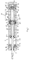
- the cylinder comprises a cylindrical body 1 which is closed at each end by respective end caps 2 and 3.
- a piston 4 is axially slidably located in the bore of the body 1 and has a piston rod 5 secured to it.
- An air-tight seal is formed between the external cylindrical surface of the piston 4 and the bore wall of the body 1 by means of a series of annular sealing rings 6, 7 and 8 located in annular grooves formed in the piston 4.
- the piston rod 5 extends through a bore 9 formed in the end cap 2 in which is located an annular bearing member 10 and an annular seal 11.
- the inner end of the bore 9 is enlarged at 12 so as to define, about the piston rod 5, an annular passageway 13 which communicates with a threaded main inlet/exhaust port 14 formed in the end cap 2.
- the end cap 2 is further formed with an auxiliary bleed passageway 15 that communicates with the annular passageway 13 via an adjustable, tapered throttle screw 16.
- the end cap 3 is similarly provided with corresponding passageways 13' and 15', a main inlet/exhaust port 14' and an adjustable throttle screw 16'.
- means are provided for affording cushioning over an extended part of each stroke.
- a sealing member 20 and associated O-ring 21 are mounted on a spigot 35 secured to a guide member 22.
- the guide member 22 has secured to it one end of a tie rod 36 and one end of a tube 37.
- the other ends of the tie rod 36 and tube 37 are telescopically engaged with, respectively, a second tube 38 and a second tie rod 39 on the respective ends of which, remote from the guide member 22, is mounted a sealing member 27 having an associated O-ring 28.
- the tubes 37 and 38 are slidably mounted in bores 40, 41 formed in the piston 4. However, rightwards movement of the tube 37 relative to the piston 4, and leftwards movement of the tube 38 relative to the piston 4, are limited by virtue of the tube ends being flared at 37' and 38' respectively.
- Each of the tubes 37, 38 houses, and each tie rod 36, 39 is surrounded by, respective identical compression springs, 42, 43, 44 and 45.
- the adjacent ends of the springs 43 and 44 abut a cylindrical spacer 46 slidably mounted on the tie rod 36 and in the tube 38, whereas the adjacent ends of the springs 42 and 45 abut a like spacer 47 slidably mounted on the tie rod 39 and in the tube 37.
- the cylinder executes its in-stroke at its full, desired velocity until it eventually reaches the position shown in Fig 1 in which both sealing members 20 and 27 are urged into their fully extended positions by the compression springs 42 to 45 and, in particular, the sealing member 20/seal 21 closes off the main entrance to the passageway 13'.
- the piston 4 Upon continued supply of compressed air to the chamber 29 the piston 4 continues its in-stroke, in cushioned fashion, for the distance marked A, during which air in the chamber 30 can exhaust through the port 14' only via the bleed passageway 15'/throttle screw 16'.
- the velocity of the piston 4 thereby reduces by an amount dependent upon the setting of the screw 16'.
- Fig 3 shows the arrangement at the commencement of cushioning during the out-stroke.
- the sealing members 20 and 27 are both in their fully extended positions but upon continued supply of compressed air to the chamber 30, the piston 4 continues its out-stroke, in cushioned fashion, over the distance A', during which air in the chamber 29 can exhaust through the port 14 only via the bleed passageway 15/throttle screw 16.
- the tie rods 36 and 39 eventually become fully telescoped within the tubes 38 and 37 respectively and the springs 42 and 45 become equally compressed.
- cushioning is afforded over an extended length (A or A') of each stroke of the cylinder and this may be varied by varying the lengths of the tubes 37 and 38 and the tie rods 36 and 39.
- Figs 1 to 3 provides for extended cushioning of a subsequent stroke even if the previous stroke is not completed. This feature is useful in the context of passenger railway carriage doors actuated by cylinders of the invention where, because of an obstruction by a passenger during closing of the doors, they are caused to re-open and then close once the passenger is clear of the doors.
Landscapes
- Engineering & Computer Science (AREA)
- Physics & Mathematics (AREA)
- Fluid Mechanics (AREA)
- Mechanical Engineering (AREA)
- General Engineering & Computer Science (AREA)
- Actuator (AREA)
- Vehicle Body Suspensions (AREA)
- Engine Equipment That Uses Special Cycles (AREA)
- Gear-Shifting Mechanisms (AREA)
Claims (3)
- Flüssigkeitsbetriebener Zylinder, der ein Gehäuse (1) mit einer Bohrung durch dieses aufweist, einen Kolben (4), der sich in Längsrichtung in der Bohrung hin und her bewegen kann und ein daran befestigtes Bewegungsübertragungselement (5) aufweist, einen Hauptflüssigkeitsauslauf (14, 14') und einen Nebenflüssigkeitsauslauf (15, 15'), die an jedem Ende der Bohrung angeordnet sind und jeweilige Dichtungen (20, 21, 27, 28), die an jeder Seite des Kolbens (4) sitzen, um den jeweiligen Hauptauslauf (14, 14') an einem vorbestimmten Punkt während der Bewegung des Kolbens (4) auf die Enden zu, schliessen, wobei bei weiterer Bewegung des Kolbens auf die Enden zu, Flüssigkeit nur durch den jeweiligen Nebenauslauf (15, 15') austreten kann und somit die weitere Bewegung des Kolbens (4) gedämpft wird, wobei jede Dichtung (20, 21, 27, 28) während der ungedämpften Bewegung des Kolbens (4) durch die jeweiligen Druckfedern (42, 43, 44, 45) in eine vom Kolben (4) entfernte Position gedrückt wird, wobei während der genannten weiteren gedämpften Bewegung des Kolbens (4) die Federn (42, 43, 44, 45) zusammengedrückt werden und es somit dem Kolben (4) ermöglicht wird, sich weiter hin zu einem der Enden der Bohrung zu bewegen, dadurch gekennzeichnet, dass jede Dichtung (20, 21, 27, 28) fest und an einem Ende der jeweiligen starren länglichen Halterungen (36, 37, 38, 39) gehalten wird, die in Längsrichtung zu dem Kolben (4) verlaufen und durch diesen bewegbar. sind, wobei die Halterungen (36, 37, 38, 39) teleskopisch ineinander eingreifen können.
- Flüssigkeitsbetriebener Zylinder, gemäss Anspruch 1, wobei jede der genannten Halterungen (36, 37, 38, 39) aus einer Stange (36, 39) und einem Rohr (37, 38) besteht, wobei die Stange (36, 39) von jeder Halterung mit dem Rohr (37, 38) der anderen Halterung ausgerichtet und von dieser teleskopisch aufgenommen werden kann.
- Flüssigkeitsbetriebener Zylinder, gemäss Anspruch 2, wobei jede Stange (36, 39) von einer ersten Druckfeder (44, 45) umschlossen ist und sich in jedem Rohr (37, 38) eine zweite Druckfeder (42, 43) befindet, wobei die erste und zweite Druckfedern (44, 43; 45, 42) einer jeden teleskopisch ineinander eingreifenden Stange und Röhre (36, 38; 39, 37) aneinander stossen und durch ein zylindrisches Distanzstück (46, 47), das bewegbar auf der Stange und in der Röhre angeordnet ist getrennt werden, wobei die Druckfedern während der ungedämpften Bewegung des Kolbens, die teleskopisch ineinander eingreifende Stange und Röhre in axial verlängerte Stellungen bewegen und somit jede Dichtung in eine vom Kolben (4) entfernte Stellung bewegen, wobei diese jedoch während der gedämpften Bewegung des Kolbens (4) zunehmend zusammengedrückt werden während die Stange und das Rohr zunehmend teleskopisch ineinander eingreifen.
Applications Claiming Priority (2)
| Application Number | Priority Date | Filing Date | Title |
|---|---|---|---|
| GB9421002A GB9421002D0 (en) | 1994-10-18 | 1994-10-18 | Fluid powered cylinder |
| GB9421002 | 1994-10-18 |
Publications (3)
| Publication Number | Publication Date |
|---|---|
| EP0708254A2 EP0708254A2 (de) | 1996-04-24 |
| EP0708254A3 EP0708254A3 (de) | 1998-03-25 |
| EP0708254B1 true EP0708254B1 (de) | 2001-12-05 |
Family
ID=10763033
Family Applications (1)
| Application Number | Title | Priority Date | Filing Date |
|---|---|---|---|
| EP95307196A Expired - Lifetime EP0708254B1 (de) | 1994-10-18 | 1995-10-11 | Druckmittelbetätigter Arbeitszylinder |
Country Status (7)
| Country | Link |
|---|---|
| US (1) | US5692429A (de) |
| EP (1) | EP0708254B1 (de) |
| CN (1) | CN1071856C (de) |
| AT (1) | ATE210248T1 (de) |
| DE (1) | DE69524360T2 (de) |
| ES (1) | ES2168339T3 (de) |
| GB (1) | GB9421002D0 (de) |
Families Citing this family (17)
| Publication number | Priority date | Publication date | Assignee | Title |
|---|---|---|---|---|
| JPH10169612A (ja) * | 1996-12-06 | 1998-06-23 | Smc Corp | 流体圧シリンダ |
| US6173938B1 (en) | 1998-09-22 | 2001-01-16 | Applied Materials, Inc. | Two speed air cylinder for slit valve motion control |
| US7351288B2 (en) * | 2003-12-22 | 2008-04-01 | Asml Holding N.V. | Shock absorbing fluidic actuator |
| US7337885B2 (en) * | 2004-12-28 | 2008-03-04 | Smc Corporation Of America | Telescoping cylinder |
| CA2507149A1 (en) * | 2005-05-12 | 2006-11-12 | P & M Design & Consulting Ltd. | Pneumatic cylinder |
| DE102005032853B3 (de) * | 2005-07-14 | 2007-02-08 | Norgren Gmbh | Arbeitszylinder mit Endlagendämpfung |
| US20070101861A1 (en) * | 2005-10-20 | 2007-05-10 | Danny Turner | Two-speed cylinder |
| JP5360564B2 (ja) * | 2009-06-03 | 2013-12-04 | Smc株式会社 | 空気圧シリンダのエアクッション機構 |
| CN102691695B (zh) * | 2011-03-23 | 2013-04-24 | 三一重工股份有限公司 | 缓冲液压缸及其控制方法、工程机械 |
| CN102162479B (zh) * | 2011-05-06 | 2013-01-02 | 浙江浦大液压机械有限公司 | 一种复合式增力油缸 |
| CN103557201B (zh) * | 2013-11-18 | 2015-12-09 | 徐州徐工液压件有限公司 | 压力缸 |
| CN104389849B (zh) * | 2014-10-13 | 2016-08-17 | 中国运载火箭技术研究院 | 一种适用于气体作动的缓冲作动装置 |
| US11215256B2 (en) * | 2018-05-14 | 2022-01-04 | Russ Wernimont | Multi-stage shock absorber and method for using the same |
| FR3096097B1 (fr) * | 2019-05-13 | 2021-09-24 | Safran Landing Systems | Vérin hydraulique equipé d’un dispositif de ralentissement de fin de course |
| CN112648304B (zh) * | 2019-10-11 | 2024-08-23 | 舍弗勒技术股份两合公司 | 密封装置及液压活塞装置 |
| CN112483510B (zh) * | 2020-12-14 | 2025-06-10 | 湖南联诚轨道装备有限公司 | 低地板有轨电车防折弯系统用缓冲缸 |
| CN114754041B (zh) * | 2022-04-08 | 2024-08-09 | 宁波悦威液压科技有限公司 | 一种行程可控的精准去刺油缸 |
Family Cites Families (10)
| Publication number | Priority date | Publication date | Assignee | Title |
|---|---|---|---|---|
| GB746801A (en) * | 1953-04-02 | 1956-03-21 | Neville Rupert Anderson | Improvements in or relating to fluid operated power cylinders |
| GB774289A (en) * | 1954-01-22 | 1957-05-08 | Us Metallic Packing Company Lt | Improvements in or relating to double-acting engine piston and cylinder assemblies |
| US2870744A (en) * | 1956-02-16 | 1959-01-27 | Hanna Engineering Works | Cushioning device for cylinders |
| US3054385A (en) * | 1961-03-20 | 1962-09-18 | Hanna Engineering Works | Fluid actuator having cushioned stop |
| US3136225A (en) * | 1962-01-29 | 1964-06-09 | Harold K Rader | Piston cushioning structure |
| GB1536417A (en) * | 1975-06-19 | 1978-12-20 | Emhart Ind | Cylinder and piston assemblies |
| DE2925885A1 (de) * | 1979-06-27 | 1981-01-22 | Wabco Fahrzeugbremsen Gmbh | Pneumatischer tuerzylinder |
| US4373427A (en) * | 1980-01-31 | 1983-02-15 | Tol-O-Matic, Inc. | Fluid pressure cylinder |
| CA1260360A (en) * | 1986-09-05 | 1989-09-26 | Alan G. Dry | Rodless cylinder |
| DE3818833A1 (de) * | 1988-06-03 | 1989-02-02 | Dimter Erwin | Kolben fuer druckluftzylinder, insbesondere fuer kolbenstangenlose zylinder |
-
1994
- 1994-10-18 GB GB9421002A patent/GB9421002D0/en active Pending
-
1995
- 1995-10-11 AT AT95307196T patent/ATE210248T1/de not_active IP Right Cessation
- 1995-10-11 ES ES95307196T patent/ES2168339T3/es not_active Expired - Lifetime
- 1995-10-11 DE DE69524360T patent/DE69524360T2/de not_active Expired - Lifetime
- 1995-10-11 EP EP95307196A patent/EP0708254B1/de not_active Expired - Lifetime
- 1995-10-17 CN CN95119946A patent/CN1071856C/zh not_active Expired - Lifetime
- 1995-10-18 US US08/544,641 patent/US5692429A/en not_active Expired - Lifetime
Also Published As
| Publication number | Publication date |
|---|---|
| DE69524360D1 (de) | 2002-01-17 |
| CN1129291A (zh) | 1996-08-21 |
| EP0708254A2 (de) | 1996-04-24 |
| EP0708254A3 (de) | 1998-03-25 |
| DE69524360T2 (de) | 2002-07-18 |
| GB9421002D0 (en) | 1994-12-07 |
| ATE210248T1 (de) | 2001-12-15 |
| ES2168339T3 (es) | 2002-06-16 |
| US5692429A (en) | 1997-12-02 |
| CN1071856C (zh) | 2001-09-26 |
Similar Documents
| Publication | Publication Date | Title |
|---|---|---|
| EP0708254B1 (de) | Druckmittelbetätigter Arbeitszylinder | |
| AU616015B2 (en) | A gas spring having a plurality of pressure chambers arranged one behind another | |
| KR830008070A (ko) | 공기압 완충기 및 그 완충방법 | |
| EP0318671A3 (de) | Pneumatischer Stossdämpfer | |
| CN114829786B (zh) | 气缸 | |
| US4955282A (en) | Uniform flow hydraulic system | |
| IT1247263B (it) | Testa di pressa pneumo-idraulica ad elevata velocita' di azionamento. | |
| US3824898A (en) | Energy conserving directional valve-cylinder combination | |
| US6536327B2 (en) | Double acting cylinder with integral end position volume chambers | |
| ITMI20002225A1 (it) | Cilindro pneumatico compatto con dispositivo di ammortizzazione | |
| WO1992011463A1 (en) | Cushioning means for pistons in fluid power systems | |
| EP1574722A2 (de) | Dämpfungsvorrichtung | |
| EP0723083B1 (de) | Druckmittelbetätigter Arbeitszylinder | |
| EP1026421A3 (de) | Gasfeder | |
| SE8202348L (sv) | Pneumatisk arbetscylinder med tre instellningslegen, foretredesvis for manover av vexellador | |
| GB1091431A (en) | Improvements in or relating to a pneumatic motor of the reciprocable type | |
| GB713242A (en) | Improvements in and relating to hydraulic buffers and draw-gear | |
| US5954315A (en) | Hydraulic spring compressor | |
| US6408739B1 (en) | Pneumatic cylinder with internal liquid dampening means | |
| GB2039996A (en) | A compressed air cylinder provided with a damping arrangement | |
| EP0119726B2 (de) | Ventil für ein hydraulisches Schlaggerät | |
| FR2288895A1 (fr) | Verin a mecanisme detecteur de fins de course incorpore | |
| SU985467A1 (ru) | Поршневой гидро(пневмо)привод двойного действи | |
| SU1479726A1 (ru) | Пневмоцилиндр | |
| JPH05280505A (ja) | シリンダ装置 |
Legal Events
| Date | Code | Title | Description |
|---|---|---|---|
| PUAI | Public reference made under article 153(3) epc to a published international application that has entered the european phase |
Free format text: ORIGINAL CODE: 0009012 |
|
| AK | Designated contracting states |
Kind code of ref document: A2 Designated state(s): AT BE CH DE DK ES FR GB IT LI NL PT SE |
|
| PUAL | Search report despatched |
Free format text: ORIGINAL CODE: 0009013 |
|
| AK | Designated contracting states |
Kind code of ref document: A3 Designated state(s): AT BE CH DE DK ES FR GB IT LI NL PT SE |
|
| 17P | Request for examination filed |
Effective date: 19980916 |
|
| 17Q | First examination report despatched |
Effective date: 20000218 |
|
| GRAG | Despatch of communication of intention to grant |
Free format text: ORIGINAL CODE: EPIDOS AGRA |
|
| GRAG | Despatch of communication of intention to grant |
Free format text: ORIGINAL CODE: EPIDOS AGRA |
|
| GRAH | Despatch of communication of intention to grant a patent |
Free format text: ORIGINAL CODE: EPIDOS IGRA |
|
| GRAH | Despatch of communication of intention to grant a patent |
Free format text: ORIGINAL CODE: EPIDOS IGRA |
|
| GRAA | (expected) grant |
Free format text: ORIGINAL CODE: 0009210 |
|
| AK | Designated contracting states |
Kind code of ref document: B1 Designated state(s): AT BE CH DE DK ES FR GB IT LI NL PT SE |
|
| PG25 | Lapsed in a contracting state [announced via postgrant information from national office to epo] |
Ref country code: NL Free format text: LAPSE BECAUSE OF FAILURE TO SUBMIT A TRANSLATION OF THE DESCRIPTION OR TO PAY THE FEE WITHIN THE PRESCRIBED TIME-LIMIT Effective date: 20011205 Ref country code: IT Free format text: LAPSE BECAUSE OF FAILURE TO SUBMIT A TRANSLATION OF THE DESCRIPTION OR TO PAY THE FEE WITHIN THE PRESCRIBED TIME-LIMIT;WARNING: LAPSES OF ITALIAN PATENTS WITH EFFECTIVE DATE BEFORE 2007 MAY HAVE OCCURRED AT ANY TIME BEFORE 2007. THE CORRECT EFFECTIVE DATE MAY BE DIFFERENT FROM THE ONE RECORDED. Effective date: 20011205 |
|
| REF | Corresponds to: |
Ref document number: 210248 Country of ref document: AT Date of ref document: 20011215 Kind code of ref document: T |
|
| REG | Reference to a national code |
Ref country code: CH Ref legal event code: NV Representative=s name: E. BLUM & CO. PATENTANWAELTE Ref country code: CH Ref legal event code: EP |
|
| REG | Reference to a national code |
Ref country code: GB Ref legal event code: IF02 |
|
| REF | Corresponds to: |
Ref document number: 69524360 Country of ref document: DE Date of ref document: 20020117 |
|
| PG25 | Lapsed in a contracting state [announced via postgrant information from national office to epo] |
Ref country code: SE Free format text: LAPSE BECAUSE OF FAILURE TO SUBMIT A TRANSLATION OF THE DESCRIPTION OR TO PAY THE FEE WITHIN THE PRESCRIBED TIME-LIMIT Effective date: 20020305 Ref country code: PT Free format text: LAPSE BECAUSE OF FAILURE TO SUBMIT A TRANSLATION OF THE DESCRIPTION OR TO PAY THE FEE WITHIN THE PRESCRIBED TIME-LIMIT Effective date: 20020305 Ref country code: DK Free format text: LAPSE BECAUSE OF FAILURE TO SUBMIT A TRANSLATION OF THE DESCRIPTION OR TO PAY THE FEE WITHIN THE PRESCRIBED TIME-LIMIT Effective date: 20020305 |
|
| ET | Fr: translation filed | ||
| NLV1 | Nl: lapsed or annulled due to failure to fulfill the requirements of art. 29p and 29m of the patents act | ||
| REG | Reference to a national code |
Ref country code: ES Ref legal event code: FG2A Ref document number: 2168339 Country of ref document: ES Kind code of ref document: T3 |
|
| PLBE | No opposition filed within time limit |
Free format text: ORIGINAL CODE: 0009261 |
|
| STAA | Information on the status of an ep patent application or granted ep patent |
Free format text: STATUS: NO OPPOSITION FILED WITHIN TIME LIMIT |
|
| 26N | No opposition filed | ||
| REG | Reference to a national code |
Ref country code: CH Ref legal event code: PFA Owner name: IMI NORGREN GMBH Free format text: IMI NORGREN GMBH#POSTFACH 1120#46515 ALPEN/NIEDERRHEIN (DE) -TRANSFER TO- IMI NORGREN GMBH#POSTFACH 1120#46515 ALPEN/NIEDERRHEIN (DE) |
|
| REG | Reference to a national code |
Ref country code: CH Ref legal event code: PUE Owner name: NORGREN GMBH Free format text: IMI NORGREN GMBH#POSTFACH 1120#46515 ALPEN/NIEDERRHEIN (DE) -TRANSFER TO- NORGREN GMBH#BRUCKSTRASSE 93#46519 ALPEN (DE) Ref country code: CH Ref legal event code: NV Representative=s name: KIRKER & CIE S.A. |
|
| PGFP | Annual fee paid to national office [announced via postgrant information from national office to epo] |
Ref country code: CH Payment date: 20081016 Year of fee payment: 14 |
|
| PGFP | Annual fee paid to national office [announced via postgrant information from national office to epo] |
Ref country code: AT Payment date: 20081013 Year of fee payment: 14 |
|
| PGFP | Annual fee paid to national office [announced via postgrant information from national office to epo] |
Ref country code: BE Payment date: 20081009 Year of fee payment: 14 |
|
| REG | Reference to a national code |
Ref country code: FR Ref legal event code: TP Ref country code: FR Ref legal event code: CD |
|
| BERE | Be: lapsed |
Owner name: NORGREN G.M.B.H. Effective date: 20091031 |
|
| REG | Reference to a national code |
Ref country code: CH Ref legal event code: PL |
|
| PG25 | Lapsed in a contracting state [announced via postgrant information from national office to epo] |
Ref country code: AT Free format text: LAPSE BECAUSE OF NON-PAYMENT OF DUE FEES Effective date: 20091011 |
|
| PG25 | Lapsed in a contracting state [announced via postgrant information from national office to epo] |
Ref country code: LI Free format text: LAPSE BECAUSE OF NON-PAYMENT OF DUE FEES Effective date: 20091031 Ref country code: CH Free format text: LAPSE BECAUSE OF NON-PAYMENT OF DUE FEES Effective date: 20091031 Ref country code: BE Free format text: LAPSE BECAUSE OF NON-PAYMENT OF DUE FEES Effective date: 20091031 |
|
| PGFP | Annual fee paid to national office [announced via postgrant information from national office to epo] |
Ref country code: ES Payment date: 20140911 Year of fee payment: 20 |
|
| PGFP | Annual fee paid to national office [announced via postgrant information from national office to epo] |
Ref country code: DE Payment date: 20141007 Year of fee payment: 20 Ref country code: GB Payment date: 20141008 Year of fee payment: 20 Ref country code: FR Payment date: 20141008 Year of fee payment: 20 |
|
| REG | Reference to a national code |
Ref country code: DE Ref legal event code: R071 Ref document number: 69524360 Country of ref document: DE |
|
| REG | Reference to a national code |
Ref country code: GB Ref legal event code: PE20 Expiry date: 20151010 |
|
| REG | Reference to a national code |
Ref country code: ES Ref legal event code: FD2A Effective date: 20160126 |
|
| PG25 | Lapsed in a contracting state [announced via postgrant information from national office to epo] |
Ref country code: GB Free format text: LAPSE BECAUSE OF EXPIRATION OF PROTECTION Effective date: 20151010 |
|
| PG25 | Lapsed in a contracting state [announced via postgrant information from national office to epo] |
Ref country code: ES Free format text: LAPSE BECAUSE OF EXPIRATION OF PROTECTION Effective date: 20151012 |