EP0708341B1 - Procédé de réglage et d'ajustement en fréquence, notamment de ponts hyperfréquences, et dispositif mettant en oeuvre un tel procédé - Google Patents
Procédé de réglage et d'ajustement en fréquence, notamment de ponts hyperfréquences, et dispositif mettant en oeuvre un tel procédé Download PDFInfo
- Publication number
- EP0708341B1 EP0708341B1 EP95440064A EP95440064A EP0708341B1 EP 0708341 B1 EP0708341 B1 EP 0708341B1 EP 95440064 A EP95440064 A EP 95440064A EP 95440064 A EP95440064 A EP 95440064A EP 0708341 B1 EP0708341 B1 EP 0708341B1
- Authority
- EP
- European Patent Office
- Prior art keywords
- radiation
- source
- frequency
- resonator
- microwave
- Prior art date
- Legal status (The legal status is an assumption and is not a legal conclusion. Google has not performed a legal analysis and makes no representation as to the accuracy of the status listed.)
- Expired - Lifetime
Links
- 238000000034 method Methods 0.000 title claims description 21
- 230000005855 radiation Effects 0.000 claims description 136
- 230000002238 attenuated effect Effects 0.000 claims description 15
- 239000002131 composite material Substances 0.000 claims description 14
- 238000004458 analytical method Methods 0.000 claims description 13
- 238000005259 measurement Methods 0.000 claims description 13
- 238000001514 detection method Methods 0.000 claims description 12
- 238000001228 spectrum Methods 0.000 claims description 8
- 238000006467 substitution reaction Methods 0.000 claims description 7
- 238000010521 absorption reaction Methods 0.000 claims description 6
- 239000003550 marker Substances 0.000 claims description 6
- 230000000694 effects Effects 0.000 claims description 4
- 230000005291 magnetic effect Effects 0.000 claims description 4
- 239000000203 mixture Substances 0.000 claims description 4
- 230000008569 process Effects 0.000 claims description 4
- 230000000737 periodic effect Effects 0.000 claims description 3
- 238000010408 sweeping Methods 0.000 claims description 3
- 238000012546 transfer Methods 0.000 claims description 3
- 230000001276 controlling effect Effects 0.000 claims 3
- 230000000712 assembly Effects 0.000 claims 1
- 238000000429 assembly Methods 0.000 claims 1
- 230000001105 regulatory effect Effects 0.000 claims 1
- 238000012800 visualization Methods 0.000 description 5
- 150000001875 compounds Chemical class 0.000 description 4
- 230000003595 spectral effect Effects 0.000 description 3
- 238000004611 spectroscopical analysis Methods 0.000 description 3
- 238000002474 experimental method Methods 0.000 description 2
- VONKRKBGTZDZNV-UHFFFAOYSA-N CC=C1CCCC1 Chemical compound CC=C1CCCC1 VONKRKBGTZDZNV-UHFFFAOYSA-N 0.000 description 1
- BGPVFRJUHWVFKM-UHFFFAOYSA-N N1=C2C=CC=CC2=[N+]([O-])C1(CC1)CCC21N=C1C=CC=CC1=[N+]2[O-] Chemical compound N1=C2C=CC=CC2=[N+]([O-])C1(CC1)CCC21N=C1C=CC=CC1=[N+]2[O-] BGPVFRJUHWVFKM-UHFFFAOYSA-N 0.000 description 1
- 230000004913 activation Effects 0.000 description 1
- 230000008878 coupling Effects 0.000 description 1
- 238000010168 coupling process Methods 0.000 description 1
- 238000005859 coupling reaction Methods 0.000 description 1
- 125000004122 cyclic group Chemical group 0.000 description 1
- 230000003247 decreasing effect Effects 0.000 description 1
- 238000000804 electron spin resonance spectroscopy Methods 0.000 description 1
- 238000012986 modification Methods 0.000 description 1
- 230000004048 modification Effects 0.000 description 1
- 238000012544 monitoring process Methods 0.000 description 1
- 230000005298 paramagnetic effect Effects 0.000 description 1
- 230000010363 phase shift Effects 0.000 description 1
- 230000011514 reflex Effects 0.000 description 1
- 230000003068 static effect Effects 0.000 description 1
- 230000007704 transition Effects 0.000 description 1
- 230000000007 visual effect Effects 0.000 description 1
Images

Classifications
-
- G—PHYSICS
- G01—MEASURING; TESTING
- G01R—MEASURING ELECTRIC VARIABLES; MEASURING MAGNETIC VARIABLES
- G01R33/00—Arrangements or instruments for measuring magnetic variables
- G01R33/20—Arrangements or instruments for measuring magnetic variables involving magnetic resonance
- G01R33/60—Arrangements or instruments for measuring magnetic variables involving magnetic resonance using electron paramagnetic resonance
-
- G—PHYSICS
- G01—MEASURING; TESTING
- G01R—MEASURING ELECTRIC VARIABLES; MEASURING MAGNETIC VARIABLES
- G01R33/00—Arrangements or instruments for measuring magnetic variables
- G01R33/20—Arrangements or instruments for measuring magnetic variables involving magnetic resonance
- G01R33/28—Details of apparatus provided for in groups G01R33/44 - G01R33/64
- G01R33/32—Excitation or detection systems, e.g. using radio frequency signals
- G01R33/36—Electrical details, e.g. matching or coupling of the coil to the receiver
- G01R33/3628—Tuning/matching of the transmit/receive coil
-
- G—PHYSICS
- G01—MEASURING; TESTING
- G01R—MEASURING ELECTRIC VARIABLES; MEASURING MAGNETIC VARIABLES
- G01R33/00—Arrangements or instruments for measuring magnetic variables
- G01R33/20—Arrangements or instruments for measuring magnetic variables involving magnetic resonance
- G01R33/44—Arrangements or instruments for measuring magnetic variables involving magnetic resonance using nuclear magnetic resonance [NMR]
- G01R33/48—NMR imaging systems
- G01R33/58—Calibration of imaging systems, e.g. using test probes, Phantoms; Calibration objects or fiducial markers such as active or passive RF coils surrounding an MR active material
- G01R33/583—Calibration of signal excitation or detection systems, e.g. for optimal RF excitation power or frequency
Definitions
- the present invention relates generally to methods of agreement between transmitter and receiver (s), in particular in the field of paramagnetic resonance spectroscopy electronics (RPE), and more particularly the techniques and means of developing the devices before measuring the characteristics of samples, and relates to a method of adjustment and overall frequency adjustment of the type transmitter / receiver, in particular of microwave bridges in electron paramagnetic resonance spectroscopy and a device implementing such a method.
- RPE paramagnetic resonance spectroscopy electronics
- RPE spectroscopy consists in simultaneously submitting a sample to be studied and characterized, to magnetic fields static (or permanent) created by an electromagnet and microwave existing in a measurement resonator and to be analyzed the microwave radiation reflected by said resonator measurement under certain conditions, called resonance, of said sample.
- microwave bridge The apparatus for generating and applying to a sample of a such microwave radiation and detection and analysis of radiation reflected by said resonator is generally called microwave bridge.
- the latter essentially consists, on the one hand, of a microwave source whose radiation can be coupled to a measurement resonator, placed in a permanent magnetic field (air gap of a magnet) in which a sample can be mounted analyze, on the other hand, attenuation and phase shift devices of said radiation and, finally, of means for detecting radiation thoughtful and analysis and / or visualization of the latter.
- said microwave bridge also includes a module, called a circulator, applying the incident radiation to resonator or to the sample / resonator assembly and collecting the radiation reflected by the latter to bring it to said means detection.
- a module called a circulator
- microwave source is of a type that can be electronically tuned over a sufficient frequency range, by example of the type known as "klystron reflex", this scanning and adjusting operation can be carried out without difficulty particular.
- some of these narrow-band sources have high reliability and spectral purity qualities, such as in particular the Gunn diode oscillators, causing their activation more and more frequent in microwave bridges.
- the scanning width obtained is not very important and it is not possible when adjusting or setting the frequency of the microwave source, whether the adjustment must be carried out a priori towards increasing values or decreasing in frequency.
- the object of the present invention is to overcome the drawbacks above and allow rapid, directed and controlled adjustment of the frequency, by carrying out a sweep of a width much greater than those that can be reached by the aforementioned known devices, this while implementing a simple structure that is easy to handle.
- the present invention relates to a method of tuning and frequency adjustment of sets of the type transmitter / receiver, in particular microwave bridges essentially comprising a main microwave source, the radiation can be coupled to a resonator arranged in a field permanent magnetic and intended to receive a sample, characterized in that it consists in subjecting the resonator to the radiation from a secondary microwave source sweeping a wide frequency band including in particular the frequency of radiation delivered by the microwave source main, said radiation from the microwave source secondary possibly mixed before application to resonator, radiant, strongly attenuated, from the source main microwave, to detect the radiation reflected by said resonator and possibly composite radiation above, to identify the relative positions in the frequency spectrum, on the one hand, the frequency of the main source, in the form of a marker or of a beat and, on the other hand, of the resonant frequency (s) of said resonator, in the form of a peak absorption by resonant frequency, to vary the frequency of the radiation delivered by the main microwave source in monitoring,
- It also relates to a device for adjusting the frequency of microwave radiation generating devices and detection and analysis of absorbed or reflected radiation resulting, adapted to the implementation of the method described above and comprising on the one hand, a secondary microwave source having a wide band of radiation frequencies, on the other part, substitution means substituting, during the adjustment operation, for radiation delivered by said main microwave source of the microwave bridge, the radiation generated by the source secondary, i.e.
- a bridge microwave is, in general, mainly constituted by a powerful, good quality microwave source 1 spectral and narrow frequency tuning band, which we will designate by main microwave source herein, by a module 2, called a circulator, which transmits the radiation microwave to a resonator 3 arranged in the air gap of a magnet 4 and in which can be mounted a sample 5 to be analyzed, by detection means 6 receiving the reflected radiation transmitted by circulator 2 and by means of display 7 and analysis 8 of the incident and / or reflected radiation, which can be used separately or simultaneously.
- a module 2 called a circulator, which transmits the radiation microwave to a resonator 3 arranged in the air gap of a magnet 4 and in which can be mounted a sample 5 to be analyzed
- detection means 6 receiving the reflected radiation transmitted by circulator 2 and by means of display 7 and analysis 8 of the incident and / or reflected radiation, which can be used separately or simultaneously.
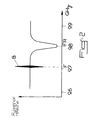
- the method of adjusting and frequency adjustment consists, in particular for a bridge microwave as described above, to submit the resonator 3 to radiation delivered by a secondary microwave source 10 sweeping a wide frequency band including in particular the frequency F of radiation delivered by the microwave source main 1, said radiation from the microwave source secondary 10 being optionally mixed, before application to resonator 3, radiant, strongly attenuated, from the source main microwave 1, to detect the radiation reflected by said resonator 3 and possibly the composite radiation above, to identify the relative positions in the frequency spectrum, the frequency F in the form of a marker or a beat B, and the resonance frequency (s) Fr of said resonator 3, under the shape of a peak or "dip" of absorption by resonant frequency, at vary the frequency F of the radiation delivered by the source main microwave 1 by controlling, in real time, the effect of this variation on the relative positions of the frequencies F and Fr above and, finally, to submit, for measurement purposes, at least one sample 5 / resonator 3 set with delivered radiation, not atten
- the source secondary 10 is also frequency controlled at source main 1 during the setting phase so that the frequency F of said main source 1 is always located at middle of the frequency band swept by the secondary source 10.
- the process can advantageously consist in slaving the display means 7, reflected and / or incident radiation at the level (s) resonator (s) 3, at main source 1, such that the frequency F of radiation from main source 1 occupies always a particular predetermined position, preferably the central position, of the frequency spectrum displayed.
- the setting of the frequency F of the main source 1 is summarizes in a simple visual adjustment of the positions of the "dip” 3 resonators or by simply centering the "dip” or absorption peak of the resonator 3 at the screen of the display means 7, displaying the signal representing the power or the amplitude of the radiation reflected by said resonator 3 as a function of the frequency, determined by the incident radiation.
- the process according to the invention may also be used to match the frequency F of the main source 1 with the frequencies Fr of a resonator 3, so to adjust the coupling of the resonance modes of the resonator 3 in such a way that they are substantially identical for the different resonances.
- the relative positions of the frequencies F and Fr can be influenced and modified by acting either on the main source 1, either on the resonator (s) 3 (which may be relatively tricky to do), or both.
- the signal corresponding to the radiation composite incident is superimposed on the signal corresponding to the reflected radiation, at the display means 7, with concordance of the frequency spectra.
- the radiation from the main microwave source 1, strongly attenuated and whose frequency is fixed, is therefore mixed radiation, not attenuated, delivered by the microwave source secondary 1 (), controlled so as to deliver radiation whose variable frequency periodically runs through all or at least part of the possible frequency range for this source 1 () and comprising in particular the frequencies F and Fr, the means 7 for viewing the reflected radiation and, where appropriate, incident, operating in accordance with said periodic scanning.
- the resonant frequency Fr of the resonator 3 is displayed by a negative peak (directed downwards), showing the absorption of incident radiation by the resonator 3 for this frequency, and the frequency F of the main microwave source 1 is identified by a marker or beat B, caused by a phenomenon of mixing and detected at the level of the detection means 6 (diode of modulation functioning as a mixer) of the radiation reflected following the application of the above-mentioned compound radiation or level of the mixing means 15 (diode), when the radiation superimposed constituting said compound radiation have very close frequencies.
- the secondary source 10, as well as a coupler circuit 11, optionally comprising a mixing means 15, may be grouped in a specific box and be mounted on a bridge microwave, removably, during the adjustment phase.
- a module for selection 12 linked by one of its inputs to the source output main microwave 1, to pass the microwave bridge, reversibly, in a first configuration, suitable for setting, in which the radiation delivered by the source main microwave 1 is used to control the means of display 7 and / or the secondary microwave source 10 and is, possibly, brought to a coupler circuit 11 to be superimposed, after strong attenuation, to radiation from the source secondary microwave 10, the radiation from said source secondary 10 or, where appropriate, the resulting compound radiation above being coupled to the resonator 3 and the radiation reflected by this the latter being displayed, in a second configuration, adapted to the measurement and analysis of the characteristics of a sample 5, in which the radiation delivered by the microwave source main 1 and having a frequency F identical to the frequency of resonance Fr of resonator 3, is applied, alone and without attenuation, to the sample 5 / resonator 3 assembly, the reflected radiation being analyzed to determine different characteristics of sample 5.
- the subject of the invention is also, as shown in the figure 1 of the accompanying drawings, a device for adjusting the frequency of microwave bridges, implementing the method described above and comprising, on the one hand, a secondary microwave source 10 having a wide band of radiation frequencies, on the other part, means 11, 12 to replace, during the operation of adjustment, to the radiation delivered by said microwave source main 1 of the microwave bridge, i.e.
- the radiation generated by the secondary source 10 ie a composite radiation formed by the mixture of radiation from microwave sources secondary 10 and primary 1, primary source 1 being significantly attenuated, and, finally, means 6, 7, 15 of detection, analysis and / or visualization of the radiation reflected by the resonator 3 and, where appropriate, radiation coupled to said resonator 3, making it possible to identify the relative positions of the frequency F of main source 1 and the resonant frequency (at least one) of the resonator 3.
- the secondary source 10 can advantageously be frequency controlled at source main 1 during the setting phase so that the frequency F of said main source 1 is always located at middle of the frequency band swept by the secondary source 10, the display means used, if applicable, which can also be slaved to primary source 1.
- the secondary microwave source 10 may consist of a broadband oscillator, associated with control means 13 allowing periodic scanning of all or part of the range of possible radiation frequencies, can be delivered by said oscillator, said means of control 13 can also control the means of visualization 7 allowing to visually locate the positions relative in the frequency spectrum, of the frequency F of the source main microwave I and the resonance frequency Fr of the resonator 3 at least present.
- the secondary microwave source 10 which is not works only during the adjustment phase of the microwave bridge, will not have to present the same spectral purity performances, stability and power than the main microwave source 1 intended for measurement and analysis, and can therefore be of high quality and at a lower price.
- the control means 13 may consist of a ramp generator will, therefore, provide a uniform and cyclic frequency sweep by the source secondary microwave 10.
- the means of substitution essentially consist of a coupler circuit 11 intended to apply to the resonator 3 the composite radiation or the radiation from the secondary source 10 and comprising, if applicable if necessary, a mixing means 15 making it possible to mix said composite radiation and possibly by a module of selection 12 of the radiation applied to the resonator 3 or to the sample 5 / resonator 3 assembly.
- the latter may advantageously be in the form of a relay of transfer, which is reversibly switchable, from a first state, suitable for adjusting the microwave bridge and in which the resonator 3 is subjected to radiation constituted by the radiation from secondary source 10 or by the superposition of radiation from main microwave sources I and secondary 10, in a second state, suitable for measuring characteristics of sample 5 and in which the set sample 5 / resonator 3 is subjected to the radiation delivered, not attenuated, by the main microwave source 1, the coupler 11 and the secondary microwave source 10 then being isolated from the microwave bridge.
- a relay of transfer which is reversibly switchable
- Figure 1 shows schematically the configurations of the transfer relay 12 in setting mode (broken lines between pads A and C / B and D) and in measurement / analysis mode (solid lines between studs A and B / C and D).
- the adjusting device according to the invention can be implemented so particularly advantageous when the microwave source main 1 is narrow band, especially when it occurs in the form of a Gunn diode oscillator mounted in a cavity resonant.
- Said adjustment device is preferably made of such that the secondary microwave source 10 and the substitution means 11, 12 (when provided) are fitted in an independent box 14, which can be mounted in series in a microwave bridge, between microwave source 1 of it and the circulator module 2.
- the device used is of simple structure and inexpensive, easy to use and install in bridges Existing and space-saving microwave.
Landscapes
- Physics & Mathematics (AREA)
- Condensed Matter Physics & Semiconductors (AREA)
- General Physics & Mathematics (AREA)
- Control Of Motors That Do Not Use Commutators (AREA)
- Measurement Of Resistance Or Impedance (AREA)
- Investigating Or Analysing Materials By Optical Means (AREA)
- Geophysics And Detection Of Objects (AREA)
Description
Claims (13)
- Procédé de réglage et d'ajustement en fréquence d'ensembles du type émetteur/récepteur, notamment de ponts hyperfréquence comprenant essentiellement une source hyperfréquence principale dont le rayonnement peut être couplé à un résonateur disposé dans un champ magnétique permanent et destiné à recevoir un échantillon, caractérisé en ce qu'il consiste à soumettre le résonateur (3) au rayonnement délivré par une source hyperfréquence secondaire (10) balayant une large bande de fréquences comprenant notamment la fréquence (F) de rayonnement délivré par la source hyperfréquence principale (1), ledit rayonnement de la source hyperfréquence secondaire (10) étant éventuellement mélangé, avant application au résonateur (3), au rayonnement, fortement atténué, de la source hyperfréquence principale (1), à détecter le rayonnement réfléchi par ledit résonateur (3) et éventuellement le rayonnement composite précité, à repérer les positions relatives, dans le spectre fréquentiel, de la fréquence (F), sous la forme d'un marqueur ou battement, et de la ou des fréquence(s) de résonance (Fr) dudit résonateur (3), sous la forme d'un pic d'absorption par fréquence de résonance, à faire varier la fréquence (F) du rayonnement délivré par la source hyperfréquence principale (1) en contrôlant, en temps réel, l'effet de cette variation sur les positions relatives des fréquences (F et Fr) précitées et, enfin, à soumettre, à des fins de mesure, au moins un ensemble échantillon (5)/résonateur (3) au rayonnement délivré, de manière non atténuée, par la source hyperfréquence principale (1), ce après réglage de la fréquence (F) sur la ou par rapport aux fréquence(s) de résonance (Fr) dudit résonateur (3).
- Procédé selon la revendication 1, caractérisé en ce que la source secondaire (10) est asservie en fréquence à la source principale (1) pendant la phase de réglage de telle manière que la fréquence (F) de ladite source principale (1) soit toujours située au milieu de la bande de fréquences balayée par la source secondaire (10).
- Procédé selon l'une quelconque des revendications 1 et 2, caractérisé en ce qu'il consiste à asservir les moyens de visualisation (7), du rayonnement réfléchi et/ou incident au niveau du résonateur (3), à la source principale (1), de telle manière que la fréquence (F) du rayonnement de la source principale (1) occupe toujours une position particulière prédéterminée, préférentiellement la position centrale, du spectre fréquentiel visualisé.
- Procédé selon l'une quelconque des revendications 1 à 3, caractérisé en ce qu'il consiste à appliquer au résonateur (3) un rayonnement incident composite constitué par la superposition, d'une part, du rayonnement délivré, en étant sensiblement atténué, par la source hyperfréquence principale (1) du pont hyperfréquence et, d'autre part, du rayonnement délivré par la source hyperfréquence secondaire (10), et à repérer, en vue du réglage, dans le(s) rayonnement(s) réfléchi et/ou incident visualisé(s), un battement (B) formant marqueur et caractérisant la fréquence (F) de la source hyperfréquence principale (1) au niveau des moyens de visualisation (7), ledit battement (B) résultant d'un phénomène de mélange dû à la combinaison des rayonnements issus des sources hyperfréquence principales (1) et secondaire (10), lorsque les fréquences de ces deux sources sont très voisines, et pouvant être relevé au niveau des moyens de détection (6) du rayonnement réfléchi ou au niveau du moyen mélangeur (15) du rayonnement incident.
- Procédé selon l'une quelconque des revendications 1 à 4, caractérisé en ce qu'il consiste à commander la source hyperfréquence secondaire (10) en vue de délivrer un rayonnement dont la fréquence variable parcourt périodiquement la totalité ou une partie au moins de la plage de fréquences de rayonnement possibles, pouvant être délivrées par ladite source (10), les moyens de visualisation (7) du rayonnement réfléchi et, le cas échéant, incident fonctionnant en accord avec ledit balayage périodique.
- Procédé selon l'une quelconque des revendications 1 à 5, caractérisé en ce qu'il consiste, au moyen d'un module de sélection (12) relié par l'une de ses entrées à la sortie de la source hyperfréquence principale (1), à faire passer le pont hyperfréquence, d'une manière réversible, d'une première configuration, adaptée au réglage, dans laquelle le rayonnement délivré par la source hyperfréquence principale (1) est utilisé pour asservir les moyens de visualisation (7) et/ou la source hyperfréquence secondaire (10) et est, éventuellement, amené à un circuit coupleur (11) pour être superposé, après une forte atténuation, au rayonnement issu de la source hyperfréquence secondaire (10), le rayonnement de ladite source secondaire (10) ou, le cas échéant, le rayonnement résultant composé précité étant couplé au résonateur (3) et le rayonnement réfléchi par ce dernier étant visualisé, à une seconde configuration, adaptée à la mesure et à l'analyse des caractéristiques d'un échantillon (5), dans laquelle le rayonnement délivré par la source hyperfréquence principale (1) et ayant une fréquence (F) identique à la fréquence de résonance (Fr) du résonateur (3), est appliqué, seul et sans atténuation, à l'ensemble échantillon (5)/résonateur (3), le rayonnement réfléchi étant analysé en vue de déterminer différentes caractéristiques de l'échantillon (5).
- Dispositif pour le réglage en fréquence d'appareils de génération de rayonnement hyperfréquence et de détection et d'analyse du rayonnement absorbé ou réfléchi résultant, notamment du type pont hyperfréquence, adapté à la mise en oeuvre du procédé selon l'une quelconque des revendications 1 à 6, caractérisé en ce qu'il comprend d'une part, une source hyperfréquence secondaire (10) présentant une large bande de fréquences de rayonnement, d'autre part, des moyens (11, 12) de substitution substituant, durant l'opération de réglage, au rayonnement délivré par ladite source hyperfréquence principale (1) du pont hyperfréquence, soit le rayonnement généré par la source secondaire (10), soit un rayonnement composite formé par le mélange des rayonnements issus des sources hyperfréquences secondaire (10) et principale (1), cette dernière étant sensiblement atténuée, et, enfin, des moyens (6, 7, 15) de détection, d'analyse et/ou de visualisation du rayonnement réfléchi par le résonateur (3) et, le cas échéant, du rayonnement couplé audit résonateur (3), les moyens de détection, d'analyse et/ou de visualisation indiquant la ou les fréquence(s) de résonance (Fr) du résonateur et la fréquence du rayonnement délivré par la source hyperfréquence principale de telle sorte qu'on peut repérer, en temps réel, les positions relatives de la fréquence (F) de la source principale (1) et de la (ou des) fréquence(s) de résonance du résonateur (3).
- Dispositif selon la revendication 7, caractérisé en ce que la source secondaire (10) est asservie en fréquence à la source principale (1) pendant la phase de réglage de telle manière que la fréquence (F) de ladite source principale (1) soit toujours située au milieu de la bande de fréquences balayée par la source secondaire (10), les moyens de visualisation (7) mis en oeuvre éventuellement pouvant également être asservis à ladite source principale (1).
- Dispositif selon l'une quelconque des revendications 7 et 8, caractérisé en ce que la source hyperfréquence secondaire (10) consiste en un oscillateur large bande, associé à des moyens de commande (13) permettant d'effectuer périodiquement un balayage de la totalité ou d'une partie de la plage de fréquences de rayonnement possibles, pouvant être délivrées par ledit oscillateur, lesdits moyens de commande (13) pouvant également contrôler les moyens de visualisation (7) permettant de repérer visuellement les positions relatives dans le spectre fréquentiel, de la fréquence (F) de la source hyperfréquence principale (1) et de la fréquence de résonance (Fr) du résonateur (3) au moins présent.
- Dispositif selon l'une quelconque des revendications 7 à 9, caractérisé en ce que les moyens de substitution sont essentiellement constitués par un circuit coupleur (11) destiné à appliquer au résonateur (3) le rayonnement composite ou le rayonnement issu de la source secondaire (10) et comprenant, le cas échéant, un moyen mélangeur (15) permettant de mélanger ledit rayonnement composite et, éventuellement, par un module de sélection (12) du rayonnement appliqué au résonateur (3) ou à l'ensemble échantillon (5)/résonateur (3).
- Dispositif selon la revendication 10, caractérisé en ce que le module de sélection (12) se présente sous la forme d'un relais de transfert, qui est commutable, de manière réversible, d'un premier état, adapté au réglage du pont hyperfréquence et dans lequel le résonateur (3) est soumis à un rayonnement constitué par le rayonnement de la source secondaire (10) ou par la superposition des rayonnements délivrés par les sources hyperfréquences principale (1) et secondaire (10), en un second état, adapté à la mesure des caractéristiques de l'échantillon (5) et dans lequel l'ensemble échantillon (5)/résonateur (3) est soumis au rayonnement délivré, de manière non atténuée, par la source hyperfréquence principale (1), le coupleur (11) et la source hyperfréquence secondaire (10) étant alors isolés du pont hyperfréquence.
- Dispositif selon l'une quelconque des revendications 7 à 11, caractérisé en ce qu'il est adapté à la mise en oeuvre du procédé lorsque la source hyperfréquence principale (1) se présente sous la forme d'un oscillateur à diode Gunn montée dans une cavité résonante.
- Dispositif selon l'une quelconque des revendications 7 à 12, caractérisé en ce que la source hyperfréquence secondaire (10) et les moyens de substitution (11, 12) sont montés dans un boítier indépendant (14), pouvant être monté en série dans un pont hyperfréquence.
Applications Claiming Priority (2)
| Application Number | Priority Date | Filing Date | Title |
|---|---|---|---|
| FR9412652 | 1994-10-19 | ||
| FR9412652A FR2726088B1 (fr) | 1994-10-19 | 1994-10-19 | Procede de reglage et d'ajustement en frequence, notamment de ponts hyperfrequences, et dispositif mettant en oeuvre un tel procede |
Publications (2)
| Publication Number | Publication Date |
|---|---|
| EP0708341A1 EP0708341A1 (fr) | 1996-04-24 |
| EP0708341B1 true EP0708341B1 (fr) | 2000-11-15 |
Family
ID=9468115
Family Applications (1)
| Application Number | Title | Priority Date | Filing Date |
|---|---|---|---|
| EP95440064A Expired - Lifetime EP0708341B1 (fr) | 1994-10-19 | 1995-10-06 | Procédé de réglage et d'ajustement en fréquence, notamment de ponts hyperfréquences, et dispositif mettant en oeuvre un tel procédé |
Country Status (5)
| Country | Link |
|---|---|
| US (1) | US5629625A (fr) |
| EP (1) | EP0708341B1 (fr) |
| JP (1) | JP3629312B2 (fr) |
| DE (2) | DE708341T1 (fr) |
| FR (1) | FR2726088B1 (fr) |
Families Citing this family (2)
| Publication number | Priority date | Publication date | Assignee | Title |
|---|---|---|---|---|
| DE10011163A1 (de) * | 2000-02-28 | 2001-09-13 | Ew Handels & Consulting Gmbh | Verfahren zur Diagnose und/oder Überwachung physiologischer oder pathologischer Veränderungen im menschlichen oder tierischen Körper und ESR-Spektrometer zur Durchführung des Verfahrens |
| JP4041900B2 (ja) * | 2005-06-28 | 2008-02-06 | 国立大学法人山形大学 | 電子スピン共鳴測定装置の自動制御装置 |
Family Cites Families (8)
| Publication number | Priority date | Publication date | Assignee | Title |
|---|---|---|---|---|
| US3879653A (en) * | 1974-02-06 | 1975-04-22 | Varian Associates | Microwave spectrometer employing a bimodal cavity resonator |
| US4803624A (en) * | 1986-09-19 | 1989-02-07 | Pilbrow John R | Electron spin resonance spectrometer |
| JPS6410652U (fr) * | 1987-07-08 | 1989-01-20 | ||
| US4888554A (en) * | 1988-08-02 | 1989-12-19 | Mcw Research Foundation, Inc. | Electron paramagnetic resonance (EPR) spectrometer |
| GB2237645B (en) * | 1989-08-17 | 1994-05-04 | Orbit Radical Instr And Equipm | Electron spin resonance spectrometers |
| DE4125592C2 (de) * | 1991-08-02 | 1994-12-08 | Bruker Analytische Messtechnik | Verfahren und Vorrichtung zum Abstimmen einer Mikrowellen-Quelle |
| JP3281007B2 (ja) * | 1991-12-06 | 2002-05-13 | 住友特殊金属株式会社 | 電子スピン共鳴装置 |
| JP3322688B2 (ja) * | 1992-04-23 | 2002-09-09 | 住友特殊金属株式会社 | 電子スピン共鳴装置 |
-
1994
- 1994-10-19 FR FR9412652A patent/FR2726088B1/fr not_active Expired - Fee Related
-
1995
- 1995-10-06 EP EP95440064A patent/EP0708341B1/fr not_active Expired - Lifetime
- 1995-10-06 DE DE0708341T patent/DE708341T1/de active Pending
- 1995-10-06 DE DE69519413T patent/DE69519413T2/de not_active Expired - Fee Related
- 1995-10-19 US US08/545,100 patent/US5629625A/en not_active Expired - Lifetime
- 1995-10-19 JP JP27154595A patent/JP3629312B2/ja not_active Expired - Lifetime
Also Published As
| Publication number | Publication date |
|---|---|
| FR2726088A1 (fr) | 1996-04-26 |
| JP3629312B2 (ja) | 2005-03-16 |
| US5629625A (en) | 1997-05-13 |
| JPH08210999A (ja) | 1996-08-20 |
| EP0708341A1 (fr) | 1996-04-24 |
| DE708341T1 (de) | 1997-04-10 |
| FR2726088B1 (fr) | 1997-01-24 |
| DE69519413D1 (de) | 2000-12-21 |
| DE69519413T2 (de) | 2001-06-28 |
Similar Documents
| Publication | Publication Date | Title |
|---|---|---|
| EP3213093B1 (fr) | Système et procédé d'analyse d'un signal hyperfréquence par imagerie | |
| US20210063243A1 (en) | Dual-comb spectroscopy | |
| EP1442282B1 (fr) | Dispositif a laser couple a une cavite par retroaction optique pour la detection de traces de gaz | |
| EP1075651B1 (fr) | Procede d'excitation d'une cavite optique pour la detection de gaz a l'etat de traces | |
| EP0077739B1 (fr) | Dispositif de mesure d'un courant ionique produit par un faisceau d'ions | |
| FR2586481A1 (fr) | Appareil pour mesurer le bruit hyperfrequence | |
| US20140306101A1 (en) | Device and method for measuring the distribution of physical quantities in an optical fiber | |
| EP1801939B1 (fr) | Dispositif de rayonnement de lumiere infrarouge, dispositif de detection de lumiere infrarouge, spectrometre a impulsions de conversion de serie chronologique, et procede de rayonnement de lumiere infrarouge | |
| FR2680248A1 (fr) | Procede et systeme de mesure de signaux electrique a haute frequence par effet electro-optique. | |
| EP0708341A1 (fr) | Procédé de réglage et d'ajustement en fréquence, notamment de ponts hyperfréquences, et dispositif mettant en oeuvre un tel procédé | |
| US6411388B1 (en) | System and method for frequency domain interferometric second harmonic spectroscopy | |
| EP0015830A1 (fr) | Appareillage de mesure du module de la fonction de transfert d'une fibre optique et son utilisation | |
| CH283102A (fr) | Dispositif permettant de faire apparaître, sur une courbe rendue visible sur l'écran d'un tube cathodique, un repère correspondant à une fréquence déterminée. | |
| EP0248737B1 (fr) | Circuit d'analyse d'un signal électrique modulé en amplitude, comprenant un transposeur de fréquence | |
| FR3122741A1 (fr) | Procédé et dispositif d’analyse de modulation térahertz à cadence rapide, profonde et large bande | |
| FR2621396A1 (fr) | Appareil de mesure de l'impedance electrique | |
| EP0913948B1 (fr) | Procédé de contrôle de l'amplitude du signal micro-onde appliqué à une horloge atomique et dispositif d'asservissement pour la mise en oeuvre de ce procédé | |
| FR2994276A1 (fr) | Procede de mesure de parametres s en mode pulse | |
| EP1227331A2 (fr) | Circuit d'excitation et de récupération du signal émis par une sonde dans un appareil de spectrométrie RMN | |
| Armstrong et al. | Demonstration of a frequency-modulated, pulsed optical parametric oscillator | |
| FR2739451A1 (fr) | Dispositif d'analyse d'un signal hyperfrequence | |
| WO2024044859A1 (fr) | Spectroscopie térahertz sélective en fréquence | |
| WO2025012308A1 (fr) | Procédé de mesure photoacoustique avec accordage en longueur d'onde d'une source de lumière | |
| FR2839151A1 (fr) | Dispositif et procede de determination du"chirp" d'un modulateur electro-optique du type mach-zehnder | |
| WO2002093118A2 (fr) | Caracterisation d'impulsions courtes faible puissance |
Legal Events
| Date | Code | Title | Description |
|---|---|---|---|
| PUAI | Public reference made under article 153(3) epc to a published international application that has entered the european phase |
Free format text: ORIGINAL CODE: 0009012 |
|
| AK | Designated contracting states |
Kind code of ref document: A1 Designated state(s): BE CH DE GB LI |
|
| 17P | Request for examination filed |
Effective date: 19961014 |
|
| GBC | Gb: translation of claims filed (gb section 78(7)/1977) | ||
| DET | De: translation of patent claims | ||
| RAP1 | Party data changed (applicant data changed or rights of an application transferred) |
Owner name: BRUKER SA |
|
| GRAG | Despatch of communication of intention to grant |
Free format text: ORIGINAL CODE: EPIDOS AGRA |
|
| RTI1 | Title (correction) |
Free format text: METHOD FOR FREQUENCY REGULATION AND ADJUSTMENT, IN PARTICULAR OF MICROWAVE BRIDGES, AND DEVICE FOR CARRYING OUT THIS METHOD |
|
| RTI1 | Title (correction) |
Free format text: METHOD FOR FREQUENCY REGULATION AND ADJUSTMENT, IN PARTICULAR OF MICROWAVE BRIDGES, AND DEVICE FOR CARRYING OUT THIS METHOD |
|
| 17Q | First examination report despatched |
Effective date: 20000218 |
|
| GRAG | Despatch of communication of intention to grant |
Free format text: ORIGINAL CODE: EPIDOS AGRA |
|
| GRAH | Despatch of communication of intention to grant a patent |
Free format text: ORIGINAL CODE: EPIDOS IGRA |
|
| GRAH | Despatch of communication of intention to grant a patent |
Free format text: ORIGINAL CODE: EPIDOS IGRA |
|
| GRAA | (expected) grant |
Free format text: ORIGINAL CODE: 0009210 |
|
| AK | Designated contracting states |
Kind code of ref document: B1 Designated state(s): BE CH DE GB LI |
|
| REG | Reference to a national code |
Ref country code: CH Ref legal event code: NV Representative=s name: WERNER FENNER PATENTANWALT Ref country code: CH Ref legal event code: EP |
|
| REF | Corresponds to: |
Ref document number: 69519413 Country of ref document: DE Date of ref document: 20001221 |
|
| GBT | Gb: translation of ep patent filed (gb section 77(6)(a)/1977) |
Effective date: 20010110 |
|
| PLBE | No opposition filed within time limit |
Free format text: ORIGINAL CODE: 0009261 |
|
| STAA | Information on the status of an ep patent application or granted ep patent |
Free format text: STATUS: NO OPPOSITION FILED WITHIN TIME LIMIT |
|
| 26N | No opposition filed | ||
| REG | Reference to a national code |
Ref country code: GB Ref legal event code: IF02 |
|
| REG | Reference to a national code |
Ref country code: CH Ref legal event code: PFA Free format text: BRUKER SA TRANSFER- BRUKER BIOSPIN SA |
|
| PGFP | Annual fee paid to national office [announced via postgrant information from national office to epo] |
Ref country code: GB Payment date: 20080912 Year of fee payment: 14 |
|
| PGFP | Annual fee paid to national office [announced via postgrant information from national office to epo] |
Ref country code: DE Payment date: 20081025 Year of fee payment: 14 |
|
| PGFP | Annual fee paid to national office [announced via postgrant information from national office to epo] |
Ref country code: BE Payment date: 20081029 Year of fee payment: 14 |
|
| PGFP | Annual fee paid to national office [announced via postgrant information from national office to epo] |
Ref country code: CH Payment date: 20090123 Year of fee payment: 14 |
|
| REG | Reference to a national code |
Ref country code: CH Ref legal event code: PCAR Free format text: WERNER FENNER PATENTANWALT;HOFACHER 1;5425 SCHNEISINGEN (CH) |
|
| BERE | Be: lapsed |
Owner name: S.A. *BRUKER BIOSPIN Effective date: 20091031 |
|
| REG | Reference to a national code |
Ref country code: CH Ref legal event code: PL |
|
| PG25 | Lapsed in a contracting state [announced via postgrant information from national office to epo] |
Ref country code: DE Free format text: LAPSE BECAUSE OF NON-PAYMENT OF DUE FEES Effective date: 20100501 |
|
| PG25 | Lapsed in a contracting state [announced via postgrant information from national office to epo] |
Ref country code: LI Free format text: LAPSE BECAUSE OF NON-PAYMENT OF DUE FEES Effective date: 20091031 Ref country code: CH Free format text: LAPSE BECAUSE OF NON-PAYMENT OF DUE FEES Effective date: 20091031 Ref country code: BE Free format text: LAPSE BECAUSE OF NON-PAYMENT OF DUE FEES Effective date: 20091031 |
|
| PG25 | Lapsed in a contracting state [announced via postgrant information from national office to epo] |
Ref country code: GB Free format text: LAPSE BECAUSE OF NON-PAYMENT OF DUE FEES Effective date: 20091006 |