EP0708384A2 - Entwickler-Behälter mit niedrigem Öffnungs/Verschluss-Widerstand - Google Patents
Entwickler-Behälter mit niedrigem Öffnungs/Verschluss-Widerstand Download PDFInfo
- Publication number
- EP0708384A2 EP0708384A2 EP95307311A EP95307311A EP0708384A2 EP 0708384 A2 EP0708384 A2 EP 0708384A2 EP 95307311 A EP95307311 A EP 95307311A EP 95307311 A EP95307311 A EP 95307311A EP 0708384 A2 EP0708384 A2 EP 0708384A2
- Authority
- EP
- European Patent Office
- Prior art keywords
- shutter
- developer container
- developer
- container according
- opening
- Prior art date
- Legal status (The legal status is an assumption and is not a legal conclusion. Google has not performed a legal analysis and makes no representation as to the accuracy of the status listed.)
- Granted
Links
- 229920001971 elastomer Polymers 0.000 claims description 5
- 239000005060 rubber Substances 0.000 claims description 4
- 230000005484 gravity Effects 0.000 claims description 3
- 229920003225 polyurethane elastomer Polymers 0.000 claims 3
- 239000000758 substrate Substances 0.000 claims 2
- 238000003384 imaging method Methods 0.000 claims 1
- 239000000463 material Substances 0.000 description 34
- 238000007789 sealing Methods 0.000 description 20
- XUIMIQQOPSSXEZ-UHFFFAOYSA-N Silicon Chemical compound [Si] XUIMIQQOPSSXEZ-UHFFFAOYSA-N 0.000 description 16
- 239000010703 silicon Substances 0.000 description 16
- 229910052710 silicon Inorganic materials 0.000 description 16
- 239000003921 oil Substances 0.000 description 15
- 239000011248 coating agent Substances 0.000 description 9
- 238000000576 coating method Methods 0.000 description 9
- -1 polyethylene Polymers 0.000 description 9
- 230000001603 reducing effect Effects 0.000 description 7
- 239000004743 Polypropylene Substances 0.000 description 6
- 229920001155 polypropylene Polymers 0.000 description 6
- JOYRKODLDBILNP-UHFFFAOYSA-N Ethyl urethane Chemical compound CCOC(N)=O JOYRKODLDBILNP-UHFFFAOYSA-N 0.000 description 5
- 239000000853 adhesive Substances 0.000 description 5
- 230000001070 adhesive effect Effects 0.000 description 5
- 238000005452 bending Methods 0.000 description 5
- 238000001746 injection moulding Methods 0.000 description 5
- 239000011247 coating layer Substances 0.000 description 4
- 238000009826 distribution Methods 0.000 description 4
- 238000009863 impact test Methods 0.000 description 4
- 230000002093 peripheral effect Effects 0.000 description 4
- 239000011347 resin Substances 0.000 description 4
- 229920005989 resin Polymers 0.000 description 4
- 239000004698 Polyethylene Substances 0.000 description 3
- 230000000694 effects Effects 0.000 description 3
- 239000013013 elastic material Substances 0.000 description 3
- 238000000034 method Methods 0.000 description 3
- 239000000088 plastic resin Substances 0.000 description 3
- 229920000573 polyethylene Polymers 0.000 description 3
- 230000008569 process Effects 0.000 description 3
- 238000000926 separation method Methods 0.000 description 3
- 230000003746 surface roughness Effects 0.000 description 3
- 239000001993 wax Substances 0.000 description 3
- 239000004793 Polystyrene Substances 0.000 description 2
- 229920005830 Polyurethane Foam Polymers 0.000 description 2
- 229920000122 acrylonitrile butadiene styrene Polymers 0.000 description 2
- 239000004676 acrylonitrile butadiene styrene Substances 0.000 description 2
- 230000000052 comparative effect Effects 0.000 description 2
- 150000001875 compounds Chemical class 0.000 description 2
- 230000006835 compression Effects 0.000 description 2
- 238000007906 compression Methods 0.000 description 2
- 239000006260 foam Substances 0.000 description 2
- 239000002783 friction material Substances 0.000 description 2
- 239000003365 glass fiber Substances 0.000 description 2
- 239000010410 layer Substances 0.000 description 2
- 238000004519 manufacturing process Methods 0.000 description 2
- 239000007769 metal material Substances 0.000 description 2
- 229920002223 polystyrene Polymers 0.000 description 2
- 239000011496 polyurethane foam Substances 0.000 description 2
- 239000000843 powder Substances 0.000 description 2
- 238000003825 pressing Methods 0.000 description 2
- 229920002379 silicone rubber Polymers 0.000 description 2
- 229910001220 stainless steel Inorganic materials 0.000 description 2
- 239000010935 stainless steel Substances 0.000 description 2
- ZOXJGFHDIHLPTG-UHFFFAOYSA-N Boron Chemical compound [B] ZOXJGFHDIHLPTG-UHFFFAOYSA-N 0.000 description 1
- 239000004677 Nylon Substances 0.000 description 1
- 239000004952 Polyamide Substances 0.000 description 1
- 229920006311 Urethane elastomer Polymers 0.000 description 1
- 230000015572 biosynthetic process Effects 0.000 description 1
- 229910052796 boron Inorganic materials 0.000 description 1
- 238000004140 cleaning Methods 0.000 description 1
- 238000005336 cracking Methods 0.000 description 1
- 230000002542 deteriorative effect Effects 0.000 description 1
- 239000000428 dust Substances 0.000 description 1
- 239000000806 elastomer Substances 0.000 description 1
- 239000004744 fabric Substances 0.000 description 1
- 238000002347 injection Methods 0.000 description 1
- 239000007924 injection Substances 0.000 description 1
- 230000001788 irregular Effects 0.000 description 1
- 238000005259 measurement Methods 0.000 description 1
- 238000012986 modification Methods 0.000 description 1
- 230000004048 modification Effects 0.000 description 1
- 229920001778 nylon Polymers 0.000 description 1
- 239000002245 particle Substances 0.000 description 1
- 229920002647 polyamide Polymers 0.000 description 1
- 229920000728 polyester Polymers 0.000 description 1
- 229920000642 polymer Polymers 0.000 description 1
- 229920002635 polyurethane Polymers 0.000 description 1
- 239000004814 polyurethane Substances 0.000 description 1
- 230000002035 prolonged effect Effects 0.000 description 1
- 230000009467 reduction Effects 0.000 description 1
- 230000004044 response Effects 0.000 description 1
- 239000002356 single layer Substances 0.000 description 1
- 238000005507 spraying Methods 0.000 description 1
- 239000000057 synthetic resin Substances 0.000 description 1
- 229920003002 synthetic resin Polymers 0.000 description 1
Images


Classifications
-
- G—PHYSICS
- G03—PHOTOGRAPHY; CINEMATOGRAPHY; ANALOGOUS TECHNIQUES USING WAVES OTHER THAN OPTICAL WAVES; ELECTROGRAPHY; HOLOGRAPHY
- G03G—ELECTROGRAPHY; ELECTROPHOTOGRAPHY; MAGNETOGRAPHY
- G03G15/00—Apparatus for electrographic processes using a charge pattern
- G03G15/06—Apparatus for electrographic processes using a charge pattern for developing
- G03G15/08—Apparatus for electrographic processes using a charge pattern for developing using a solid developer, e.g. powder developer
- G03G15/0822—Arrangements for preparing, mixing, supplying or dispensing developer
- G03G15/0877—Arrangements for metering and dispensing developer from a developer cartridge into the development unit
- G03G15/0881—Sealing of developer cartridges
- G03G15/0886—Sealing of developer cartridges by mechanical means, e.g. shutter, plug
-
- G—PHYSICS
- G03—PHOTOGRAPHY; CINEMATOGRAPHY; ANALOGOUS TECHNIQUES USING WAVES OTHER THAN OPTICAL WAVES; ELECTROGRAPHY; HOLOGRAPHY
- G03G—ELECTROGRAPHY; ELECTROPHOTOGRAPHY; MAGNETOGRAPHY
- G03G15/00—Apparatus for electrographic processes using a charge pattern
- G03G15/06—Apparatus for electrographic processes using a charge pattern for developing
- G03G15/08—Apparatus for electrographic processes using a charge pattern for developing using a solid developer, e.g. powder developer
- G03G15/0822—Arrangements for preparing, mixing, supplying or dispensing developer
- G03G15/0848—Arrangements for testing or measuring developer properties or quality, e.g. charge, size, flowability
- G03G15/0849—Detection or control means for the developer concentration
- G03G15/0855—Detection or control means for the developer concentration the concentration being measured by optical means
-
- G—PHYSICS
- G03—PHOTOGRAPHY; CINEMATOGRAPHY; ANALOGOUS TECHNIQUES USING WAVES OTHER THAN OPTICAL WAVES; ELECTROGRAPHY; HOLOGRAPHY
- G03G—ELECTROGRAPHY; ELECTROPHOTOGRAPHY; MAGNETOGRAPHY
- G03G15/00—Apparatus for electrographic processes using a charge pattern
- G03G15/06—Apparatus for electrographic processes using a charge pattern for developing
- G03G15/08—Apparatus for electrographic processes using a charge pattern for developing using a solid developer, e.g. powder developer
- G03G15/0822—Arrangements for preparing, mixing, supplying or dispensing developer
- G03G15/0865—Arrangements for supplying new developer
-
- G—PHYSICS
- G03—PHOTOGRAPHY; CINEMATOGRAPHY; ANALOGOUS TECHNIQUES USING WAVES OTHER THAN OPTICAL WAVES; ELECTROGRAPHY; HOLOGRAPHY
- G03G—ELECTROGRAPHY; ELECTROPHOTOGRAPHY; MAGNETOGRAPHY
- G03G2215/00—Apparatus for electrophotographic processes
- G03G2215/06—Developing structures, details
- G03G2215/066—Toner cartridge or other attachable and detachable container for supplying developer material to replace the used material
- G03G2215/0692—Toner cartridge or other attachable and detachable container for supplying developer material to replace the used material using a slidable sealing member, e.g. shutter
Definitions
- Figure 7 is an enlarged sectional view of a portion of the refill developer container.
- FIGs 1, 2 and 3 illustrate the first embodiment of the refill developer container of the sliding shutter type in accordance with the present invention.
- Figure 4 shows the seal member and sliding cap member, that is, the essential portions of the first embodiment of the present invention.
- a refill developer container C has an opening la for refilling developer into a developer hopper 6 of the copying machine main assembly P, and comprises an actual container portion 1 for containing developer 5, a shutter member 3 for exposing or covering the opening la, and a cap member 4 as guiding means for guiding and supporting the shutter member 3 so that the shutter member 3 can take a closed position where it seals the opening 1a, and an open position to which it retracts from the closed position in order to expose the opening 1a.
- On the shutter member surface 3a facing the opening an elastic seal member 4 is pasted.
- the cap member 2 has- shutter guide portions 2c for guiding the shutter member 3 in the direction indicated by an arrow mark A in Figure 2. They are disposed on both lateral sides of the cap member 3, relative to the sliding direction of the shutter member 3.
- the seal member 4 covers the area from the edge of the opening 1a to guide member 2c.
- the recessed portion 2d of the uneven flange surface 2d is preferred to be continuous and is connected to either the opening la of the actual container portion 1 or the external edge of the cap member 2, or both.
- the recessed portion illustrated in Figure 4(a) is constituted of a groove.
- a large number of grooves are arranged substantially in parallel to the opening/closing direction of the shutter member 3.
- Provision of plural recess portions substantially in parallel to the shutter opening/closing direction is very preferable in terms of reducing the shutter operating force, and simplifying the formation of the cap member 2.
- Figure 4(b, c and d) show other examples of the recessed portion of the uneven flange surface 2d: (b) radial grooves radiating from the developer refilling opening 2a of the cap member 2; (c) curved grooves; and (d) recessed portions connected among a large number of projections (islands) 2d-1 erected from the flat flange surface.
- the seal member 4 is formed of soft elastic material. It is required to continue to seal between the cap member 2 and shutter member 3, so that the developer 5 contained in the actual container portion 1 is prevented from leaking from between the cap member 2 and shutter member 3 when the refill developer container is subjected to impact such as the one generated during the impact test or the like, and to reduce the opening/closing resistance of the shutter member 3 so that the shutter member 3 can slide with low resistance on the flange surface 2b of the cap member 2, which has the developer refilling opening 2a. More specifically, as the material for the seal member 4, sponge of silicon rubber, urethane, or the like, are usable.
- a preferable material would be high density polyurethane foam which has a hardness of 20° to 70°, a permanent compressive deformation ratio of 4% or less, a friction coefficient of 0.8 or less, a cell size of 60 ⁇ m to 300 ⁇ m, and a specific gravity of 0.2 to 0.5. It is preferable that such high density urethane foam is compressed by 5% to 50%, more preferably, 10% to 30%, when used.
- the cap member 2 is attached to the actual container portion 1. It has the opening 2a for refilling the developer 5 from the actual container portion 1 into the developer hopper 6 of the copying machine main assembly, and a U-shaped shutter guide portion 2c for guiding the opening/closing movement of the shutter member 3. Also, the cap member must be structured to keep the joint between itself and the actual container portion 1 sealed. As for the material for the chap member 2, the same material as the shutter member 3 can be considered.
- the results reveal that the shutter opening/closing resistance is more effectively reduced when the average peak-to-peak distance Sm is no less than 100 ⁇ m; the center line average height Ra is no less than 2 ⁇ m; the ten point average height Rz is no less than 20 ⁇ m; and the maximum height Rmax is no less than 30 ⁇ m.
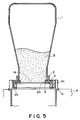
- the developer refilling opening diameter can be increased by approximately 10 mm, compared to when the seal member 4 is pasted on the cap member 2 as shown in Figure 5.
- the time it takes to empty the developer 5 from the refill developer container C into the developer hopper 6, drops to approximately 15 seconds, making it possible to finish refilling the developer 5 into the copying machine main assembly P in half the time it takes in the case of the conventional container.
- the continuous recessed portions 2d were formed at the same time when the cap member 2 was molded using the injection molding method, and were arranged in parallel to the shutter opening/closing direction, as shown in Figure 4(a), the average peak-to-peak distance Sm being 170 ⁇ m; the center line average height Ra.being 2.7 ⁇ m; the ten point average height Rz being 27 ⁇ m; and the maximum height Rmax being approximately 165 ⁇ m.
- the shutter opening/closing resistance was approximately 3.3 kgf to 3.7 kgf, and the developer 5 in the refill developer container C could be refilled into the developer hopper 6, leaving almost none in the container C.
- the refill developer container in accordance with the present invention was subjected to a vibration test, a low pressure test, a drop test, and a high temperature/high humidity test, as a product distribution test.
- a vibration test was conducted using 10 refill developer containers C.
- An anomaly such as a developer leak or the like could not be observed in any of the above tests.
- the containers C were subjected to an image forming test, but no problem occurred; picture quality was excellent.
- Figure 3 illustrates how the developer 5 is refilled into the developer hopper 6 of the copying machine main assembly P, using the refill developer container C in accordance with the present invention.
- the opening la is exposed so that the developer 5 in the actual container portion 1 drops through the opening la to refill the developer hopper 6.
- the operator closes the opening la by grasping the knob 3c of the shutter member 3 and moving the shutter member 3 in the direction opposite to the arrow A direction.
- the opening la is sealed by the seal member 4 pasted in such a manner as to seal the joint between the shutter member 4 and cap member 2, preventing the developer 5 from leaking and scattering. Further, when the refill developer container C was separated from the developer hopper 6 after the developer 5 was refilled into the developer hopper 6 and the shutter member 3 was closed as described above, scattering of the developer 5 or the like could not be observed.
- Figure 1 is a longitudinal section of a comparative refill developer container, illustrating its structure.
- the seal member 4 was pasted on the cap member 4, at the bottom periphery portion of the developer refilling opening 2a, which required allowance for the pasting margin.
- the developer refilling opening became smaller by approximately 10 mm than the one in the first embodiment. Consequently, developer discharge efficiency was reduced, which resulted in prolonged developer discharge time. Further, the amount of the developer to be filled in the refill developer container had to be reduced by approximately 10% because of the longer filling time.
- urethane rubber was used as the material for the seal member 4, and the seal member 4 was attached to the shutter member 3 by means of integrally forming the seal member 4 and the shutter member 3 using the two color injection molding method. Otherwise, this embodiment was the same as the first embodiment.
- the seal member 4 is pasted to the shutter member 3 when assembling the refill developer container C, the seal member 4 is compressed along the peripheral edge of the developer refilling opening 1a, that is, the edge between the opening 2a of the cap member 2, and the flange surface 2b, being elastically deformed by the edge which presses into the sealing member 4; therefore, sealing properties are further improved.
- the seal member 4 is formed of soft elastic material. It is required to keep the joint between the cap member 2 and shutter member 3 sealed, so that the developer 5 in the refill developer container C is prevented from leaking out upon impact generated during the drop test or the like. At the same time, it is required to generate as small a frictional resistance as possible when it slides on the flange surface 2b of the cap member flange, which has the developer refilling opening 2a, so that the opening/closing resistance of the shutter member 3 can be reduced.
- sponge of silicon rubber, urethane, or the like is used as the material for the seal member 4.
- it is compressible low density polyurethane foam which has a hardness of 20° to 70°, a permanent compression deformation of no more than 4%, a friction coefficient of no more than 0.8, a cell size of 60 ⁇ m to 300 ⁇ m, and a specific gravity of 0.2 to 0.5.
- the compression of the seal member 4 it is preferable to increase compressibility and compressive stress to maintain a high level of sealing properties, in response to a recent tendency to increase the capacity of the refill developer container.
- compressibility is small
- compressive stress is also small, failing to provide satisfactory sealing properties; therefore, the developer 5 leaks during the drop impact test or the like.
- the shutter member 3 are liable to deform upon drop impact or the like. Therefore, if the set value for the compressibility of the seal member 4 is small, sealing properties is liable to be instantly lost.
- the compressibility of the seal member 4 is preferred to be within a range of 5% to 50%, more preferably, a range of 20% to 40%.
- the compressive stress of the seal member 4 it is preferred to be within a range of 0.1 kg/cm to 2.0 kg/cm, more preferably, a range of 0.6 kg/cm to 1.5 kg/cm (refer to JIS-K7220).
- the surface of the seal member 4 that is, the surface which slides on the opposing member as the shutter is opened or closed, is preferred to be flat and have as small a frictional resistance as possible.
- a single layer film made of polyester, polypropylene, polyamide (commercial name: nylon), polyethylene, fluoro-resin, or the like, or a compound layer film made of the preceding materials was applied to the surface of the shutter member 4, the smoothness of the sliding surface was improved, whereby the shutter opening/closing resistance was effectively reduced.
- the aforementioned sliding film surface was coated with silicon oil, silicon wax, silicon coating, or the like in order to reduce the frictional resistance, the shutter opening/closing resistance could be further reduced.
- the thickness of the film used in this embodiment is preferred to be no less than 4 ⁇ m and no more than 100 ⁇ m. When it exceeds 100 ⁇ m, the elasticity of the seal member 4 is liable to be suppressed by the rigidity of the film, failing to deliver satisfactory sealing properties. In terms of making the best use of the elasticity of the seal member 4, the film thickness is preferred to be no more than 50 ⁇ m. However, in terms of film production, it is rather difficult to produce, with consistency, film with a thickness of no more than 4 ⁇ m. Thus, in consideration of the above concern, as well as adhesiveness to the seal member, and film strength relative to sliding friction or the like, the film thickness is preferred to be no less than 10 ⁇ m.
- the thickness of the layer of silicon oil or silicon wax coated on the film surface to reduce frictional resistance is preferred to be within a range of 0.05 ⁇ m to 2.00 ⁇ m. This is due to the following reasons. When the coating layer thickness is no more than 0.05 ⁇ m, the coating layer is not stable enough to function effectively, and when it is no less than 2 ⁇ m, it shows a tendency to be partially peeled by friction. Therefore, in order to deliver reliable friction reducing effects, and to prevent the separation of the coating layer, the coating layer thickness is preferable to be within a range of 0.1 ⁇ m to 0.5 ⁇ m.
- the bending elasticity modulus of the shutter member 3 is also desired to be kept within a proper range. More specifically, it is preferable to be within a range of 20,000 kg/cm to 100,000 kg/cm, more preferably, a range of 50,000 kg/cm to 80,000 kg/cm (refer to JIS-7203).
- the structure of the refill developer container C in this embodiment limits the choice of materials which can be coated on the surface of the seal member 4 in order to reduce its frictional resistance, since the surface of the seal member 4 remains directly in contact with the developer 5 until refilling occurs.
- the seal member 4 is liable to become deformed, delivering unsatisfactory sealing properties. Therefore, it is more desirable that the frictional resistance of the shutter surface 3d, which is the surface opposite to the surface 3a on which the seal member 4 is pasted, is reduced.
- such material as silicon oil, silicon resin, fluoro-resin, paraffinic waxes, ultra-high polymer polyethylene, or the like, is coated on the shutter surface 3d using means such as coating, pasting, spraying, or the like.
- silicon oil, which is coated, and silicic coating film, which is pasted, are preferable as easily processable low cost materials.
- the amount of the coating material when it is excessively small, a satisfactory oil film cannot be formed; therefore, the shutter opening/closing resistance cannot be effectively reduced. Contrarily, when the amount of the coating material is too much, the coated surface becomes sticky, allowing dust or developer to stick thereto.
- the amount of the coating material is preferable to be within a range of 0.01 mg/cm to 0.5 mg/cm, more preferably, 0.05 mg/cm to 0.1 mg/cm.
- the same continuous recessed portions 2d as those in the first embodiment were formed, being aligned in parallel, in the opening/closing direction of the shutter member 3, as illustrated in Figure 4(a).
- the average peak-to-peak distance Sm was 170 ⁇ m; the center line average height Ra, 2.7 ⁇ m; the ten point average height Rz, 27 ⁇ m; and the maximum height Rmax was approximately 165 ⁇ m.
- the same material as Embodiment 1 was used.
- a film was pasted, which was constituted of a 40 ⁇ m thick drawn polypropylene base film, and 0.2 ⁇ m thick silicic coat applied on the base film.
- silicon oil was applied on the shutter surface 3d, which was the surface opposite to the surface on which the seal member was pasted. Its viscosity was 3,000 cSt, and the coated amount was approximately 0.1 mg/cm.
- the shutter opening/closing resistance was measured using 20 refill developer containers C structured as described above. It was approximately 2.0 kgf to 2.5 kgf.
- the shutter surface 3d which is the surface opposite to the surface 3a on which the seal member 4 was pasted, was not treated at all. Otherwise, the structure was the same as the preceding one. Twenty such refill developer containers C were produced to measure the shutter opening/closing resistance. It was approximately 2.5 kgf to 3.5 kgf.
- a positioning jig is used to keep the positional accuracy within a range of ⁇ 0.1 mm.
- a predetermined amount of silicon oil is uniformly coated, using cloth, paper, or the like, on the shutter member 4, on the surface 3d, which is the surface opposite to the side where the seal member 4 has been pasted.
- it is important to uniformly apply the oil so that the oil does not collect at the peripheral edges, apexes of the irregular surface, and the like, of the shutter member 3.
- the silicon oil was applied after the seal member 4 was pasted on the shutter member 3. However, there will be no problem even if the seal member 4 is pasted after the silicon oil is coated on the shutter member 3.
- the next step is a step in which the shutter member 3 is assembled into the shutter guide portion 2c of the cap member 2.
- a pressing jig is used to prevent the surface of the seal member 4 from being damaged, or to prevent the film pasted on the seal member surface from being damaged on the surface or edges, or being peeled.
- the pressing jig is manipulated through the opening 2a which is located between the cap member 2 and actual container portion 1. As the shutter member 2 is inserted all the way into the cap member 2, a cap unit is completed.
- the surface roughness in the embodiments of the present invention was measured using the following apparatus set to the specifications given below.
- the hardness of the seal member in the embodiments of the present invention which was measured using the urethane foam hardness test (JIS K6401), was spring type A hardness.
Landscapes
- Physics & Mathematics (AREA)
- General Physics & Mathematics (AREA)
- Dry Development In Electrophotography (AREA)
- Electrophotography Configuration And Component (AREA)
Applications Claiming Priority (3)
| Application Number | Priority Date | Filing Date | Title |
|---|---|---|---|
| JP27846594 | 1994-10-18 | ||
| JP6278465A JP3031829B2 (ja) | 1994-10-18 | 1994-10-18 | 現像剤補給容器 |
| JP278465/94 | 1994-10-18 |
Publications (3)
| Publication Number | Publication Date |
|---|---|
| EP0708384A2 true EP0708384A2 (de) | 1996-04-24 |
| EP0708384A3 EP0708384A3 (de) | 1997-01-22 |
| EP0708384B1 EP0708384B1 (de) | 2001-09-26 |
Family
ID=17597714
Family Applications (1)
| Application Number | Title | Priority Date | Filing Date |
|---|---|---|---|
| EP95307311A Expired - Lifetime EP0708384B1 (de) | 1994-10-18 | 1995-10-16 | Entwickler-Behälter mit niedrigem Öffnungs/Verschluss-Widerstand |
Country Status (6)
| Country | Link |
|---|---|
| US (1) | US5649270A (de) |
| EP (1) | EP0708384B1 (de) |
| JP (1) | JP3031829B2 (de) |
| KR (1) | KR0164000B1 (de) |
| CN (1) | CN1067774C (de) |
| DE (1) | DE69522886T2 (de) |
Cited By (1)
| Publication number | Priority date | Publication date | Assignee | Title |
|---|---|---|---|---|
| EP2450752A1 (de) * | 2010-11-09 | 2012-05-09 | Oki Data Corporation | Aufbewahrungskörper für Entwickler, Bilderzeugungseinheit und Bilderzeugungsvorrichtung |
Families Citing this family (7)
| Publication number | Priority date | Publication date | Assignee | Title |
|---|---|---|---|---|
| JP3658081B2 (ja) * | 1996-03-27 | 2005-06-08 | キヤノン株式会社 | トナー補給容器 |
| JPH10198163A (ja) * | 1996-11-12 | 1998-07-31 | Minolta Co Ltd | 現像装置 |
| US7128380B2 (en) * | 2002-04-10 | 2006-10-31 | Canon Kabushiki Kaisha | Recording liquid container, ink jet recording apparatus, and cartridge collecting apparatus |
| WO2008085126A1 (en) * | 2007-01-08 | 2008-07-17 | Tfm Sweden Aktiebolag | Method and device for refilling of toner powder |
| JP6083954B2 (ja) | 2011-06-06 | 2017-02-22 | キヤノン株式会社 | 現像剤補給容器及び現像剤補給システム |
| JP6066281B2 (ja) * | 2012-12-04 | 2017-01-25 | 株式会社リコー | 粉体収容器、現像ユニット、プロセスユニット及び画像形成装置 |
| JP7206856B2 (ja) * | 2018-11-30 | 2023-01-18 | 株式会社リコー | トナー搬送装置、現像装置、プロセスカートリッジ、及び、画像形成装置 |
Family Cites Families (3)
| Publication number | Priority date | Publication date | Assignee | Title |
|---|---|---|---|---|
| JPH0273382A (ja) * | 1988-09-09 | 1990-03-13 | Seiko Epson Corp | トナー受け渡し部接続分離機構 |
| JP2565575B2 (ja) * | 1989-12-08 | 1996-12-18 | 三田工業株式会社 | トナーカートリッジ |
| JP3210175B2 (ja) * | 1993-06-10 | 2001-09-17 | キヤノン株式会社 | 現像剤補給容器及び前記容器の組み立て方法 |
-
1994
- 1994-10-18 JP JP6278465A patent/JP3031829B2/ja not_active Expired - Fee Related
-
1995
- 1995-10-16 US US08/543,619 patent/US5649270A/en not_active Expired - Lifetime
- 1995-10-16 DE DE69522886T patent/DE69522886T2/de not_active Expired - Lifetime
- 1995-10-16 EP EP95307311A patent/EP0708384B1/de not_active Expired - Lifetime
- 1995-10-18 KR KR1019950035910A patent/KR0164000B1/ko not_active Expired - Lifetime
- 1995-10-18 CN CN95118703A patent/CN1067774C/zh not_active Expired - Fee Related
Cited By (2)
| Publication number | Priority date | Publication date | Assignee | Title |
|---|---|---|---|---|
| EP2450752A1 (de) * | 2010-11-09 | 2012-05-09 | Oki Data Corporation | Aufbewahrungskörper für Entwickler, Bilderzeugungseinheit und Bilderzeugungsvorrichtung |
| US8655236B2 (en) | 2010-11-09 | 2014-02-18 | Oki Data Corporation | Developer storage body, image forming unit and image forming apparatus |
Also Published As
| Publication number | Publication date |
|---|---|
| CN1131286A (zh) | 1996-09-18 |
| US5649270A (en) | 1997-07-15 |
| KR960015114A (ko) | 1996-05-22 |
| CN1067774C (zh) | 2001-06-27 |
| DE69522886D1 (de) | 2001-10-31 |
| JPH08119350A (ja) | 1996-05-14 |
| EP0708384B1 (de) | 2001-09-26 |
| JP3031829B2 (ja) | 2000-04-10 |
| DE69522886T2 (de) | 2002-04-11 |
| KR0164000B1 (ko) | 1999-03-20 |
| EP0708384A3 (de) | 1997-01-22 |
Similar Documents
| Publication | Publication Date | Title |
|---|---|---|
| KR0134307B1 (ko) | 현상제 공급용기 및 그 조립 방법 | |
| US6094550A (en) | Developing apparatus | |
| US5282003A (en) | Copier and printer toner hopper sealing device | |
| EP0708384B1 (de) | Entwickler-Behälter mit niedrigem Öffnungs/Verschluss-Widerstand | |
| JPH0762777B2 (ja) | 粉体現像剤収納容器 | |
| US7076186B1 (en) | Tear-strip seal and tear-seal assembly using a pre-cut tear initialization and a toner hopper, toner cartridge and image forming apparatus using same and method of manufacturing same seal, toner hopper and toner cartridge assembly | |
| JP3492222B2 (ja) | 現像剤補給容器 | |
| US5933692A (en) | Developer regulating member with elastic layer supporting section having high elastic limit value and developing apparatus using the same | |
| JP3320300B2 (ja) | 現像剤補給容器 | |
| JP3054323B2 (ja) | 現像剤補給容器 | |
| JP3514402B2 (ja) | 現像剤補給容器 | |
| EP1239340A2 (de) | Walze | |
| JPH08146734A (ja) | 現像剤補給容器 | |
| US5079590A (en) | Sealing mechanism for toner handling apparatus | |
| JP2001027844A (ja) | 現像装置、プロセスカートリッジ、画像形成装置 | |
| US5842092A (en) | Toner cartridge and toner leakage preventing tape | |
| JPH11143202A (ja) | トナー供給容器 | |
| JPH08123176A (ja) | 現像剤補給容器 | |
| JP2002072650A (ja) | 現像剤収納容器および画像形成装置 | |
| JPS63202771A (ja) | 現像装置 | |
| JP5326726B2 (ja) | 封鎖構造、現像装置、清掃装置、および画像形成装置 | |
| JP3514400B2 (ja) | 現像剤補給容器 | |
| JPH01178985A (ja) | 現像装置 | |
| JP3814430B2 (ja) | トナー補給容器 | |
| JPH0720683Y2 (ja) | 現像装置 |
Legal Events
| Date | Code | Title | Description |
|---|---|---|---|
| PUAI | Public reference made under article 153(3) epc to a published international application that has entered the european phase |
Free format text: ORIGINAL CODE: 0009012 |
|
| AK | Designated contracting states |
Kind code of ref document: A2 Designated state(s): DE FR GB IT |
|
| PUAL | Search report despatched |
Free format text: ORIGINAL CODE: 0009013 |
|
| AK | Designated contracting states |
Kind code of ref document: A3 Designated state(s): DE FR GB IT |
|
| 17P | Request for examination filed |
Effective date: 19970604 |
|
| 17Q | First examination report despatched |
Effective date: 19990706 |
|
| GRAG | Despatch of communication of intention to grant |
Free format text: ORIGINAL CODE: EPIDOS AGRA |
|
| GRAG | Despatch of communication of intention to grant |
Free format text: ORIGINAL CODE: EPIDOS AGRA |
|
| GRAG | Despatch of communication of intention to grant |
Free format text: ORIGINAL CODE: EPIDOS AGRA |
|
| GRAH | Despatch of communication of intention to grant a patent |
Free format text: ORIGINAL CODE: EPIDOS IGRA |
|
| GRAH | Despatch of communication of intention to grant a patent |
Free format text: ORIGINAL CODE: EPIDOS IGRA |
|
| GRAA | (expected) grant |
Free format text: ORIGINAL CODE: 0009210 |
|
| AK | Designated contracting states |
Kind code of ref document: B1 Designated state(s): DE FR GB IT |
|
| REF | Corresponds to: |
Ref document number: 69522886 Country of ref document: DE Date of ref document: 20011031 |
|
| ET | Fr: translation filed | ||
| REG | Reference to a national code |
Ref country code: GB Ref legal event code: IF02 |
|
| PLBE | No opposition filed within time limit |
Free format text: ORIGINAL CODE: 0009261 |
|
| STAA | Information on the status of an ep patent application or granted ep patent |
Free format text: STATUS: NO OPPOSITION FILED WITHIN TIME LIMIT |
|
| 26N | No opposition filed | ||
| PGFP | Annual fee paid to national office [announced via postgrant information from national office to epo] |
Ref country code: IT Payment date: 20071019 Year of fee payment: 13 |
|
| PGFP | Annual fee paid to national office [announced via postgrant information from national office to epo] |
Ref country code: FR Payment date: 20071022 Year of fee payment: 13 |
|
| REG | Reference to a national code |
Ref country code: FR Ref legal event code: ST Effective date: 20090630 |
|
| PG25 | Lapsed in a contracting state [announced via postgrant information from national office to epo] |
Ref country code: IT Free format text: LAPSE BECAUSE OF NON-PAYMENT OF DUE FEES Effective date: 20081016 |
|
| PG25 | Lapsed in a contracting state [announced via postgrant information from national office to epo] |
Ref country code: FR Free format text: LAPSE BECAUSE OF NON-PAYMENT OF DUE FEES Effective date: 20081031 |
|
| PGFP | Annual fee paid to national office [announced via postgrant information from national office to epo] |
Ref country code: GB Payment date: 20131018 Year of fee payment: 19 Ref country code: DE Payment date: 20131031 Year of fee payment: 19 |
|
| REG | Reference to a national code |
Ref country code: DE Ref legal event code: R119 Ref document number: 69522886 Country of ref document: DE |
|
| GBPC | Gb: european patent ceased through non-payment of renewal fee |
Effective date: 20141016 |
|
| PG25 | Lapsed in a contracting state [announced via postgrant information from national office to epo] |
Ref country code: GB Free format text: LAPSE BECAUSE OF NON-PAYMENT OF DUE FEES Effective date: 20141016 Ref country code: DE Free format text: LAPSE BECAUSE OF NON-PAYMENT OF DUE FEES Effective date: 20150501 |