EP0708466A1 - Poignée d'interrupteur avec arrangement de réglage - Google Patents
Poignée d'interrupteur avec arrangement de réglage Download PDFInfo
- Publication number
- EP0708466A1 EP0708466A1 EP95116200A EP95116200A EP0708466A1 EP 0708466 A1 EP0708466 A1 EP 0708466A1 EP 95116200 A EP95116200 A EP 95116200A EP 95116200 A EP95116200 A EP 95116200A EP 0708466 A1 EP0708466 A1 EP 0708466A1
- Authority
- EP
- European Patent Office
- Prior art keywords
- switch knob
- opening
- projecting pieces
- knob
- grooves
- Prior art date
- Legal status (The legal status is an assumption and is not a legal conclusion. Google has not performed a legal analysis and makes no representation as to the accuracy of the status listed.)
- Granted
Links
- 230000008878 coupling Effects 0.000 description 5
- 238000010168 coupling process Methods 0.000 description 5
- 238000005859 coupling reaction Methods 0.000 description 5
- 230000004044 response Effects 0.000 description 3
- 230000009118 appropriate response Effects 0.000 description 2
- 238000000465 moulding Methods 0.000 description 2
- 239000011347 resin Substances 0.000 description 2
- 229920005989 resin Polymers 0.000 description 2
- 238000005452 bending Methods 0.000 description 1
Images


Classifications
-
- H—ELECTRICITY
- H01—ELECTRIC ELEMENTS
- H01H—ELECTRIC SWITCHES; RELAYS; SELECTORS; EMERGENCY PROTECTIVE DEVICES
- H01H15/00—Switches having rectilinearly-movable operating part or parts adapted for actuation in opposite directions, e.g. slide switch
- H01H15/02—Details
-
- H—ELECTRICITY
- H01—ELECTRIC ELEMENTS
- H01H—ELECTRIC SWITCHES; RELAYS; SELECTORS; EMERGENCY PROTECTIVE DEVICES
- H01H15/00—Switches having rectilinearly-movable operating part or parts adapted for actuation in opposite directions, e.g. slide switch
- H01H15/02—Details
- H01H15/06—Movable parts; Contacts mounted thereon
-
- H—ELECTRICITY
- H01—ELECTRIC ELEMENTS
- H01H—ELECTRIC SWITCHES; RELAYS; SELECTORS; EMERGENCY PROTECTIVE DEVICES
- H01H9/00—Details of switching devices, not covered by groups H01H1/00 - H01H7/00
- H01H9/02—Bases, casings, or covers
- H01H9/06—Casing of switch constituted by a handle serving a purpose other than the actuation of the switch, e.g. by the handle of a vacuum cleaner
- H01H2009/068—Casing of switch constituted by a handle serving a purpose other than the actuation of the switch, e.g. by the handle of a vacuum cleaner with switches mounted on a handlebar, e.g. for motorcycles, fork lift trucks, etc.
-
- H—ELECTRICITY
- H01—ELECTRIC ELEMENTS
- H01H—ELECTRIC SWITCHES; RELAYS; SELECTORS; EMERGENCY PROTECTIVE DEVICES
- H01H9/00—Details of switching devices, not covered by groups H01H1/00 - H01H7/00
- H01H9/02—Bases, casings, or covers
- H01H9/06—Casing of switch constituted by a handle serving a purpose other than the actuation of the switch, e.g. by the handle of a vacuum cleaner
-
- Y—GENERAL TAGGING OF NEW TECHNOLOGICAL DEVELOPMENTS; GENERAL TAGGING OF CROSS-SECTIONAL TECHNOLOGIES SPANNING OVER SEVERAL SECTIONS OF THE IPC; TECHNICAL SUBJECTS COVERED BY FORMER USPC CROSS-REFERENCE ART COLLECTIONS [XRACs] AND DIGESTS
- Y10—TECHNICAL SUBJECTS COVERED BY FORMER USPC
- Y10T—TECHNICAL SUBJECTS COVERED BY FORMER US CLASSIFICATION
- Y10T74/00—Machine element or mechanism
- Y10T74/20—Control lever and linkage systems
- Y10T74/20576—Elements
- Y10T74/20636—Detents
Definitions
- the present invention relates to an apparatus for positioning a switch knob, and more specifically, to an apparatus for positioning a switch knob used for controlling on/off or the like of a battery feeded head lamp attached on a bicycle or the like.
- Fig. 7 is a side view showing a head lamp 1 employing a conventional positioning apparatus, attached on a handle 7 of a bicycle 43.
- Fig. 8 shows a specific structure of the head lamp 1 attached on a handle 7 of Fig. 7
- Fig. 9 is a front view
- Fig. 10 is a rear view thereof.
- an attachment part 2 consists of an upper member 9 and a lower member 11 which are rotatable around a pin 45.
- attachment screw 17 When attached to handle 7 of a bicycle, attachment screw 17 is removed, upper member 9 and lower member 11 are rotated about the pin 45 with their end portions expanded, and attachment part 2 is attached on the handle 7 of a bicycle with a rubber 47 wound around the handle 7. Thereafter, attachment screw 17 is fastened, so that a force gripping handle 7 is applied to the upper and lower members 9 and 11, and hence the attachment part 2 is firmly attached on handle 7 with rubber 47 interposed.
- a switch knob 3 for controlling on/off of the lamp is provided, which is operated referring to an indication mark 5.
- An attachment part 13 is attached on a lower portion of head lamp 1 by means of an attachment screw or the like.
- a lever 15 used for attachment/detachment to and from the attachment part 2 is provided.
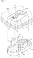
- Fig. 11 is a perspective view of switch knob 3 of Fig. 10 separated from lamp body 25 and a portion of the lamp body 25 viewed from the inside of the head lamp 1.
- Opening 19 has opposing sidewalls 60a and 60b, the sidewall 60a is provided with two vertical grooves 61a and the sidewall 60b is provided with two vertical grooves 61b, which grooves each has semi-circular cross section and extending in thickness direction of the plate of the lamp body 25.
- a switch plate 49 having a bent portion, and a terminal plate 51 positioned above a tip end of switch plate 49 are provided.
- a pair of first projecting pieces 53a, 53b and a pair of second projecting pieces 57a and 57b are attached on the inner surface of a knob body 27 of switch knob 3.
- the space between the first projecting piece 53a and the second projecting piece 57b, and the distance between the first projecting piece 53b and the second projecting piece 57a correspond to the space between opposing sidewalls 60a and 60b of the opening 19.
- first projecting pieces 53a and 53b On the outer surfaces of the first projecting pieces 53a and 53b, semi-spherical projections 55a (not shown) and 55b are provided respectively.
- guide portions 37a and 37b having a triangular cross section are formed in a direction parallel to the upper surface of the knob body 27.
- a third projecting piece 59 facing toward the switch plate 49 is attached.
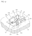
- Fig. 12 is a perspective view showing the switch knob 3 fitted in the opening 19, from the state of Fig. 11.
- guide portions 37a and 37b formed at the second projecting pieces 57a and 57b respectively are engaged with the inner surface of lamp body 25 at the edges of opening 19, and guide sliding operation of switch knob 3 in the direction of the arrow.
- switch knob 3 is positioned corresponding to a power off state. When the switch knob 3 slides in the direction of the arrow from this state, each of the projections 55a and 55b move to and engage with vertical grooves which are next to the vertical grooves with which the projections have been engaged, and the position of the switch knob 3 is stabilized.
- the third projecting piece 59 projecting from the central portion of knob body 27 to the direction of the switch plate 49 also moves in the direction of the arrow, pushes up the tip end of switch plate 49, so that the tip end is brought into contact with the terminal plate 51. Therefore, the power is turned on and light is emitted from the head lamp 1.
- projections 55a and 55b cannot be fitted with high precision in the vertical grooves 61a and 61b, and the projections cannot apply appropriate pressing force. As a result, good response of clicking cannot be obtained by the positioning apparatus.
- the present invention was made to solve the above described problems, and its object is to provide an apparatus for positioning a switch knob which can surely provides appropriate click response.
- the apparatus for positioning a switch knob in accordance with the present invention including a body, on which the switch knob is attached, having an opening corresponding to the switch knob; at least two grooves provided in the thickness direction of the body, at a portion of a sidewall of the opening; a switch knob body which is a main portion of the switch knob and having a shape appropriate for covering the opening; a pair of projecting pieces provided projecting from one surface of the switch knob body and spaced from each other by such a distance that allows the projecting pieces to be in contact with the sidewalls of the opening; a beam portion having opposing ends supported, formed in at least one of the pair of projecting pieces; and a projection formed at the beam portion and which can be fitted in one of the grooves.
- a beam portion having opposing ends supported is provided on a pair of projecting pieces provided projecting from one surface of the switch knob body, and a projection formed at the beam portion engages with the groove, so that stable engagement between the groove and the projection is realized, and satisfactory response can be obtained when the switch knob is positioned.
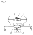
- Fig. 1 shows how a head lamp incorporating the apparatus for positioning a switch knob in accordance with one embodiment of the present invention is attached.
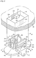
- Fig. 2 is a perspective view of a switch knob 3 separated from a lamp body 25 and a portion of a lamp body 25 viewed from the inside of the head lamp 1 of Fig. 1.
- Fig. 3 is a cross section taken along the line III-III of Fig. 2.
- Fig. 4 is a cross section taken along the line IV-IV of Fig. 2.
- Fig. 5 shows a state when switch knob 3 is fitted in the opening 19 of lamp body 25, from the state of Fig. 2.
- Fig. 6 is a cross section taken along the line VI-VI of Fig. 5.
- Fig. 7 is a side view showing the head lamp employing the conventional positioning apparatus attached on a handle of a bicycle.
- Fig. 8 shows a specific structure of head lamp 1 attached to handle 7 of Fig. 7.
- Fig. 9 is a front view of the head lamp 1 in the state of Fig. 8.
- Fig. 10 is a rear view of the head lamp 1 in the state of Fig. 8.
- Fig. 11 is a perspective view showing a switch knob 3 of Fig. 10 separated from lamp body 25 and a portion of lamp body 25 viewed from the inside of head lamp 1.
- Fig. 12 is a perspective view showing the switch knob 3 fitted in opening 19 of lamp body 25, from the state of Fig. 11.
- Fig. 1 is a rear view showing how a head lamp incorporating the apparatus for positioning a switch knob in accordance with one embodiment of the present invention is attached, which corresponds to Fig. 10 of the prior art.
- a switch knob 3 for changing, in three steps, the state of electrical connection of the lamp, by sliding in lateral direction with reference to an indication mark 5.
- Other portions are similar to those of the prior art shown in Fig. 10. Therefore, description thereof is not repeated.
- Fig. 2 is a perspective view showing switch knob 3 of Fig. 1 separated from lamp body 25 and a portion of lamp body 25 viewed from the inside of head lamp 1.
- Fig. 3 is a cross section taken along the line III-III of Fig. 2
- Fig. 4 is a cross section taken along the line IV-IV of Fig. 2.
- Opening 19 has opposing sidewalls 20a and 20b, and the sidewall 20a has three vertical grooves 21a at the central portion and sidewall 20b has three vertical grooves 21b at the central portion, which groove each have semi-circular cross section and extending in the thickness direction of the opening 19.
- a switch coupling portion 23 connected to a terminal is positioned at a central portion of opening 19.
- knob body 27 On an outer surface of knob body 27 which is the main portion of switch knob 3, a knob piece 29 is provided, so as to facilitate sliding operation of switch knob 3.
- a pair of first projecting pieces 31a and 31b are formed spaced from each other by such a distance that allows the projecting pieces to be in contact with the opposing sidewalls 20a and 20b of opening 19.
- elongate holes 32a, 32b and elongate holes 34a and 34b are provided parallel to each other and to the surface of the knob body 27, and by the provision of these holes, there are beam portions 33a and 33b formed with opposing ends supported.
- projections 35a and 35b having semi-circular cross section are formed.
- guide portions 37a and 37b having triangular cross sections are formed parallel to the upper surface of the knob body 27.
- a pair of plate shaped second projecting pieces 39a and 39b are formed from the inner surface of knob body 27.
- support members 41a and 41b are attached, so as to reinforce the second projecting pieces 39a and 39b against bending.
- the switch knob 3 including the first and second projecting pieces is formed integrally by resin molding.
- Fig. 5 is a perspective view showing the switch knob 3 fitted in the opening 19 of lamp body 25, from the state of Fig. 2, and Fig. 6 is a cross section taken along the line VI-VI of Fig. 5.
- guide portions 37a and 37b of the first projecting pieces 31a and 31b engage the inner surface of lamp body 25 at the edges of opening 19, and guides movement of switch knob 3 in the direction of the arrow.
- the projections 35a and 35b formed at the beam portions 33a and 33b of the first projecting pieces 31a and 31b respectively engage with any of the three vertical grooves 21a and any of the three vertical grooves 21b formed on the sidewalls of opening 19.
- the projections 35a and 35b are shown engaged with the central one of the three vertical grooves 21a and of 21b.
- the pair of second projecting pieces 39a and 39b are positioned sandwiching a switch coupling portion 23.
- the switch knob 3 is slid in the direction of the arrow while it is engaged with the opening 19 of lamp body 25, projections 35a and 35b move from any of the grooves of the vertical grooves 21a and 21b with which the projections have been engaged to adjacent other groove and engaged therewith.
- projections 35a and 35b are provided at beam portions 33a and 33b which have opposing ends supported, the projections engage with the vertical grooves 21a and 21b with satisfactory resiliency. Therefore, appropriate response of clicking and stable movement and stopping of the switch knob 3 are ensured.
- the switch coupling portion 23 also moves in the direction of the arrow, sandwiched by the pair of second projecting pieces 39a and 39b.
- the position of the switch coupling portion 23 changes, electrical connection between the power supply and the lamp in the head lamp 1 changes, and thus on/off of the lamp can be controlled.
- the number of grooves may be two, four or more.
- the switch plate 49 and the terminal plate 51 of the prior art may be used.
- the switch knob may be slid with the projection provided on only one of the projections and the grooves provided only one of the sidewalls.
Landscapes
- Slide Switches (AREA)
- Lighting Device Outwards From Vehicle And Optical Signal (AREA)
- Tumbler Switches (AREA)
- Arrangements Of Lighting Devices For Vehicle Interiors, Mounting And Supporting Thereof, Circuits Therefore (AREA)
- Rotary Switch, Piano Key Switch, And Lever Switch (AREA)
- Switch Cases, Indication, And Locking (AREA)
Applications Claiming Priority (2)
| Application Number | Priority Date | Filing Date | Title |
|---|---|---|---|
| JP25201894A JPH08115636A (ja) | 1994-10-18 | 1994-10-18 | 切換つまみの位置決め装置 |
| JP252018/94 | 1994-10-18 |
Publications (2)
| Publication Number | Publication Date |
|---|---|
| EP0708466A1 true EP0708466A1 (fr) | 1996-04-24 |
| EP0708466B1 EP0708466B1 (fr) | 1998-01-07 |
Family
ID=17231445
Family Applications (1)
| Application Number | Title | Priority Date | Filing Date |
|---|---|---|---|
| EP95116200A Expired - Lifetime EP0708466B1 (fr) | 1994-10-18 | 1995-10-13 | Poignée d'interrupteur avec arrangement de mise en position |
Country Status (9)
| Country | Link |
|---|---|
| US (1) | US5862714A (fr) |
| EP (1) | EP0708466B1 (fr) |
| JP (1) | JPH08115636A (fr) |
| CN (1) | CN1039265C (fr) |
| AU (1) | AU690325B2 (fr) |
| CA (1) | CA2160280C (fr) |
| DE (1) | DE69501382T2 (fr) |
| DK (1) | DK0708466T3 (fr) |
| TW (1) | TW319748B (fr) |
Families Citing this family (11)
| Publication number | Priority date | Publication date | Assignee | Title |
|---|---|---|---|---|
| JP2000288960A (ja) * | 1999-04-01 | 2000-10-17 | Mobiletron Electronics Co Ltd | 電動工具の速度を変える制御機構 |
| US6380502B1 (en) * | 2001-05-25 | 2002-04-30 | S-B Power Tool Company | Detented slide switch mechanism |
| US6734376B2 (en) * | 2002-06-19 | 2004-05-11 | Shimano Inc. | Electrical switch device for bicycle |
| EP1455260A1 (fr) * | 2003-03-06 | 2004-09-08 | Hewlett-Packard Development Company, L.P. | Dispositifs de contrôle d'accès pour systèmes de traitement de données, boítiers et sous-ensembles |
| JP4409342B2 (ja) * | 2004-04-13 | 2010-02-03 | オリンパス株式会社 | 操作スイッチ機構 |
| US6998546B1 (en) * | 2005-02-18 | 2006-02-14 | Lear Corporation | Switch assembly for a vehicle |
| JP4784441B2 (ja) * | 2006-08-15 | 2011-10-05 | 日本電気株式会社 | 嵌合部材、レバー操作部材、スライドスイッチ部材、及びこれらの嵌合方法、並びに携帯電話機器 |
| US7728240B2 (en) * | 2007-11-08 | 2010-06-01 | Cooper Technologies Company | Electrical control device |
| JP5377485B2 (ja) * | 2008-07-10 | 2013-12-25 | 三菱電機株式会社 | エレベータの操作パネル装置 |
| JP6333060B2 (ja) * | 2014-05-19 | 2018-05-30 | 日本アンテナ株式会社 | 端子台 |
| CN113545874A (zh) * | 2021-09-07 | 2021-10-26 | 深圳市飞猫电器有限公司 | 防水冲牙器 |
Citations (3)
| Publication number | Priority date | Publication date | Assignee | Title |
|---|---|---|---|---|
| US3242297A (en) * | 1963-04-30 | 1966-03-22 | Cutler Hammer Inc | Electric switch superstructures |
| DE2900726A1 (de) * | 1978-01-17 | 1979-07-19 | Elettroplast Spa | Elastisches schnappsystem fuer elektrische schalter, insbesondere fuer schnurschalter, mit einem elastischen organ, das zusammen mit einem eine metallische kontaktbruecke tragenden laeufer als formteil ausgebildet ist |
| US4441000A (en) * | 1981-03-06 | 1984-04-03 | Canon Kabushiki Kaisha | Slide switch mechanism |
Family Cites Families (5)
| Publication number | Priority date | Publication date | Assignee | Title |
|---|---|---|---|---|
| US4190754A (en) * | 1978-11-20 | 1980-02-26 | Motorola, Inc. | Slide switch actuating apparatus |
| JPS5923125U (ja) * | 1982-08-03 | 1984-02-13 | アルプス電気株式会社 | スライドスイツチ |
| US4994636A (en) * | 1989-12-07 | 1991-02-19 | Duracraft Corporation | Electrical control device |
| US5147990A (en) * | 1991-04-01 | 1992-09-15 | Motorola, Inc. | Integral slide switch |
| US5315079A (en) * | 1993-01-04 | 1994-05-24 | Illinois Tool Works Inc. | PCB mounted 6PDT slide switch |
-
1994
- 1994-10-18 JP JP25201894A patent/JPH08115636A/ja active Pending
-
1995
- 1995-10-11 CA CA002160280A patent/CA2160280C/fr not_active Expired - Fee Related
- 1995-10-12 AU AU33195/95A patent/AU690325B2/en not_active Ceased
- 1995-10-13 DE DE69501382T patent/DE69501382T2/de not_active Expired - Fee Related
- 1995-10-13 DK DK95116200.7T patent/DK0708466T3/da active
- 1995-10-13 EP EP95116200A patent/EP0708466B1/fr not_active Expired - Lifetime
- 1995-10-14 TW TW084110831A patent/TW319748B/zh active
- 1995-10-18 CN CN95119950A patent/CN1039265C/zh not_active Expired - Fee Related
-
1997
- 1997-05-27 US US08/863,413 patent/US5862714A/en not_active Expired - Fee Related
Patent Citations (3)
| Publication number | Priority date | Publication date | Assignee | Title |
|---|---|---|---|---|
| US3242297A (en) * | 1963-04-30 | 1966-03-22 | Cutler Hammer Inc | Electric switch superstructures |
| DE2900726A1 (de) * | 1978-01-17 | 1979-07-19 | Elettroplast Spa | Elastisches schnappsystem fuer elektrische schalter, insbesondere fuer schnurschalter, mit einem elastischen organ, das zusammen mit einem eine metallische kontaktbruecke tragenden laeufer als formteil ausgebildet ist |
| US4441000A (en) * | 1981-03-06 | 1984-04-03 | Canon Kabushiki Kaisha | Slide switch mechanism |
Also Published As
| Publication number | Publication date |
|---|---|
| JPH08115636A (ja) | 1996-05-07 |
| TW319748B (fr) | 1997-11-11 |
| CN1039265C (zh) | 1998-07-22 |
| EP0708466B1 (fr) | 1998-01-07 |
| US5862714A (en) | 1999-01-26 |
| DE69501382D1 (de) | 1998-02-12 |
| CA2160280A1 (fr) | 1996-04-19 |
| HK1007244A1 (en) | 1999-04-01 |
| DK0708466T3 (da) | 1998-05-04 |
| AU690325B2 (en) | 1998-04-23 |
| DE69501382T2 (de) | 1998-06-04 |
| CA2160280C (fr) | 1999-12-21 |
| CN1129844A (zh) | 1996-08-28 |
| AU3319595A (en) | 1996-05-02 |
Similar Documents
| Publication | Publication Date | Title |
|---|---|---|
| EP0708466B1 (fr) | Poignée d'interrupteur avec arrangement de mise en position | |
| US5278372A (en) | Keyboard having connecting parts with downward open recesses | |
| US10768658B2 (en) | Multi-directional input device | |
| US6211474B1 (en) | Multi-input switch | |
| US6222144B1 (en) | Pushbutton switch | |
| US6669503B2 (en) | Connector having a function of reliably correcting the position of an object to be connected | |
| US6091033A (en) | Vehicle-mounted knob switch device | |
| US20060000699A1 (en) | Push switch | |
| US20160351355A1 (en) | Switch | |
| HK1007244B (en) | Switch knob with positioning arrangement | |
| EP0184185A2 (fr) | Interrupteur à bouton-poussoir | |
| US5698909A (en) | Multi-function switch | |
| EP1223594B1 (fr) | Interrupteur coulissant | |
| US4361739A (en) | Two-directional switch | |
| US7811114B2 (en) | Connector with improved latching mechanism | |
| GB2315306A (en) | Shift knob assembly | |
| US3959618A (en) | Switch actuator rocker handle | |
| JP4023884B2 (ja) | スイッチ装置の接点開閉機構 | |
| JPS6321285B2 (fr) | ||
| EP0018728B1 (fr) | Interrupteur électrique à levier d'actionnement pivotant | |
| US4812603A (en) | Dimmer switch | |
| JPH0280844A (ja) | 自動変速機のシフトレバー | |
| CN220180978U (zh) | 一种自适应调节结构 | |
| US20050095886A1 (en) | Card connector having an eject mechanism easy to operate and assuring reliable movement | |
| JPH021783Y2 (fr) |
Legal Events
| Date | Code | Title | Description |
|---|---|---|---|
| PUAI | Public reference made under article 153(3) epc to a published international application that has entered the european phase |
Free format text: ORIGINAL CODE: 0009012 |
|
| AK | Designated contracting states |
Kind code of ref document: A1 Designated state(s): BE CH DE DK FR GB IT LI LU NL |
|
| RIN1 | Information on inventor provided before grant (corrected) |
Inventor name: FUJIMOTO, TAKUYA |
|
| 17P | Request for examination filed |
Effective date: 19960515 |
|
| GRAG | Despatch of communication of intention to grant |
Free format text: ORIGINAL CODE: EPIDOS AGRA |
|
| 17Q | First examination report despatched |
Effective date: 19970507 |
|
| GRAG | Despatch of communication of intention to grant |
Free format text: ORIGINAL CODE: EPIDOS AGRA |
|
| GRAH | Despatch of communication of intention to grant a patent |
Free format text: ORIGINAL CODE: EPIDOS IGRA |
|
| GRAH | Despatch of communication of intention to grant a patent |
Free format text: ORIGINAL CODE: EPIDOS IGRA |
|
| GRAA | (expected) grant |
Free format text: ORIGINAL CODE: 0009210 |
|
| AK | Designated contracting states |
Kind code of ref document: B1 Designated state(s): BE CH DE DK FR GB IT LI LU NL |
|
| PG25 | Lapsed in a contracting state [announced via postgrant information from national office to epo] |
Ref country code: LI Free format text: LAPSE BECAUSE OF FAILURE TO SUBMIT A TRANSLATION OF THE DESCRIPTION OR TO PAY THE FEE WITHIN THE PRESCRIBED TIME-LIMIT Effective date: 19980107 Ref country code: IT Free format text: LAPSE BECAUSE OF FAILURE TO SUBMIT A TRANSLATION OF THE DESCRIPTION OR TO PAY THE FEE WITHIN THE PRE;WARNING: LAPSES OF ITALIAN PATENTS WITH EFFECTIVE DATE BEFORE 2007 MAY HAVE OCCURRED AT ANY TIME BEFORE 2007. THE CORRECT EFFECTIVE DATE MAY BE DIFFERENT FROM THE ONE RECORDED.SCRIBED TIME-LIMIT Effective date: 19980107 Ref country code: FR Free format text: LAPSE BECAUSE OF FAILURE TO SUBMIT A TRANSLATION OF THE DESCRIPTION OR TO PAY THE FEE WITHIN THE PRESCRIBED TIME-LIMIT Effective date: 19980107 Ref country code: CH Free format text: LAPSE BECAUSE OF FAILURE TO SUBMIT A TRANSLATION OF THE DESCRIPTION OR TO PAY THE FEE WITHIN THE PRESCRIBED TIME-LIMIT Effective date: 19980107 Ref country code: BE Free format text: LAPSE BECAUSE OF FAILURE TO SUBMIT A TRANSLATION OF THE DESCRIPTION OR TO PAY THE FEE WITHIN THE PRESCRIBED TIME-LIMIT Effective date: 19980107 |
|
| REG | Reference to a national code |
Ref country code: CH Ref legal event code: EP |
|
| REF | Corresponds to: |
Ref document number: 69501382 Country of ref document: DE Date of ref document: 19980212 |
|
| REG | Reference to a national code |
Ref country code: DK Ref legal event code: T3 |
|
| EN | Fr: translation not filed | ||
| REG | Reference to a national code |
Ref country code: CH Ref legal event code: PL |
|
| PG25 | Lapsed in a contracting state [announced via postgrant information from national office to epo] |
Ref country code: LU Free format text: LAPSE BECAUSE OF NON-PAYMENT OF DUE FEES Effective date: 19981013 |
|
| PLBE | No opposition filed within time limit |
Free format text: ORIGINAL CODE: 0009261 |
|
| STAA | Information on the status of an ep patent application or granted ep patent |
Free format text: STATUS: NO OPPOSITION FILED WITHIN TIME LIMIT |
|
| 26N | No opposition filed | ||
| REG | Reference to a national code |
Ref country code: GB Ref legal event code: IF02 |
|
| PGFP | Annual fee paid to national office [announced via postgrant information from national office to epo] |
Ref country code: DE Payment date: 20061005 Year of fee payment: 12 |
|
| PGFP | Annual fee paid to national office [announced via postgrant information from national office to epo] |
Ref country code: GB Payment date: 20061011 Year of fee payment: 12 |
|
| PGFP | Annual fee paid to national office [announced via postgrant information from national office to epo] |
Ref country code: DK Payment date: 20061013 Year of fee payment: 12 |
|
| PGFP | Annual fee paid to national office [announced via postgrant information from national office to epo] |
Ref country code: NL Payment date: 20061015 Year of fee payment: 12 |
|
| REG | Reference to a national code |
Ref country code: DK Ref legal event code: EBP |
|
| GBPC | Gb: european patent ceased through non-payment of renewal fee |
Effective date: 20071013 |
|
| NLV4 | Nl: lapsed or anulled due to non-payment of the annual fee |
Effective date: 20080501 |
|
| PG25 | Lapsed in a contracting state [announced via postgrant information from national office to epo] |
Ref country code: DE Free format text: LAPSE BECAUSE OF NON-PAYMENT OF DUE FEES Effective date: 20080501 |
|
| PG25 | Lapsed in a contracting state [announced via postgrant information from national office to epo] |
Ref country code: NL Free format text: LAPSE BECAUSE OF NON-PAYMENT OF DUE FEES Effective date: 20080501 Ref country code: DK Free format text: LAPSE BECAUSE OF NON-PAYMENT OF DUE FEES Effective date: 20071031 |
|
| PG25 | Lapsed in a contracting state [announced via postgrant information from national office to epo] |
Ref country code: GB Free format text: LAPSE BECAUSE OF NON-PAYMENT OF DUE FEES Effective date: 20071013 |