EP0708495B1 - Connecteur électrique - Google Patents
Connecteur électrique Download PDFInfo
- Publication number
- EP0708495B1 EP0708495B1 EP95307397A EP95307397A EP0708495B1 EP 0708495 B1 EP0708495 B1 EP 0708495B1 EP 95307397 A EP95307397 A EP 95307397A EP 95307397 A EP95307397 A EP 95307397A EP 0708495 B1 EP0708495 B1 EP 0708495B1
- Authority
- EP
- European Patent Office
- Prior art keywords
- contact
- housing
- contact member
- electrical connector
- members
- Prior art date
- Legal status (The legal status is an assumption and is not a legal conclusion. Google has not performed a legal analysis and makes no representation as to the accuracy of the status listed.)
- Expired - Lifetime
Links
- 239000000463 material Substances 0.000 claims description 3
- 238000004891 communication Methods 0.000 claims description 2
- 230000014759 maintenance of location Effects 0.000 description 2
- 238000004519 manufacturing process Methods 0.000 description 2
- 238000006073 displacement reaction Methods 0.000 description 1
- 238000003780 insertion Methods 0.000 description 1
- 230000037431 insertion Effects 0.000 description 1
- 230000013011 mating Effects 0.000 description 1
- 238000000034 method Methods 0.000 description 1
- 238000012986 modification Methods 0.000 description 1
- 230000004048 modification Effects 0.000 description 1
- 238000000465 moulding Methods 0.000 description 1
- 239000012811 non-conductive material Substances 0.000 description 1
- 230000000717 retained effect Effects 0.000 description 1
- 238000007790 scraping Methods 0.000 description 1
- 238000003466 welding Methods 0.000 description 1
Images


Classifications
-
- H—ELECTRICITY
- H01—ELECTRIC ELEMENTS
- H01R—ELECTRICALLY-CONDUCTIVE CONNECTIONS; STRUCTURAL ASSOCIATIONS OF A PLURALITY OF MUTUALLY-INSULATED ELECTRICAL CONNECTING ELEMENTS; COUPLING DEVICES; CURRENT COLLECTORS
- H01R43/00—Apparatus or processes specially adapted for manufacturing, assembling, maintaining, or repairing of line connectors or current collectors or for joining electric conductors
- H01R43/20—Apparatus or processes specially adapted for manufacturing, assembling, maintaining, or repairing of line connectors or current collectors or for joining electric conductors for assembling or disassembling contact members with insulating base, case or sleeve
-
- H—ELECTRICITY
- H01—ELECTRIC ELEMENTS
- H01R—ELECTRICALLY-CONDUCTIVE CONNECTIONS; STRUCTURAL ASSOCIATIONS OF A PLURALITY OF MUTUALLY-INSULATED ELECTRICAL CONNECTING ELEMENTS; COUPLING DEVICES; CURRENT COLLECTORS
- H01R13/00—Details of coupling devices of the kinds covered by groups H01R12/70 or H01R24/00 - H01R33/00
- H01R13/40—Securing contact members in or to a base or case; Insulating of contact members
- H01R13/405—Securing in non-demountable manner, e.g. moulding, riveting
- H01R13/41—Securing in non-demountable manner, e.g. moulding, riveting by frictional grip in grommet, panel or base
Definitions
- This invention relates generally to electrical connectors and pertains more particularly to simplified and less expensive methods of manufacturing electrical connectors.
- a widespread practice in electrical connector manufacture is to precisely dispose a plurality of contact members in positions mutually desired in the ultimate connector housing and then to precision mold the housing about the contact members. Given the precision in both the contact member disposition in the mold and in the precision of the mold itself, coplanarity of contact member contact portions relative to the housing in the ultimate connector is satisfactorily achieved.
- a simpler and less costly practice in use is molding the housing and then inserting contact members in contact member receiving channels in the housing.
- US-A-4860445 and EP-A-408451 which both describe an electrical connector comprising a housing of electrically insulative material and contact members resident in the housing, in contact member receiving channels.
- the contacts are pressed to the rearmost portion of the channels and set in place by ultrasonic welding.
- the contact members are press-fitted in the channels, the problem addressed being avoidance of scrapings during insertion which might prevent the contact members from reaching the channel bases.
- a problem attends achieving coplanarity of contact member contact portions, i.e., where the preformed housing exhibits warping or bowing.
- the housing typically defines stop positions for inserted contact members. Where warping or bowing is at hand, the stop positions are not coplanar and the inserted contact members accordingly do not exhibit coplanarity.
- the present invention has as its primary object the achievement of contact member coplanarity in the face of warping or bowing in preformed connector housings.
- the invention provides an electrical connector comprising a housing of electrically insulative material and contact members resident in said housing, said contact members defining contact portions and means for retaining said contact members in said housing, said housing having a plurality of channels, a distinct one of said contact members residing in each said channel, and first and second slots in communication with each said channel, said contact member retaining means being resident in said first and second slots and retentively engaged with a side wall of each of said first and second slots, to permit variable positioning of said contact member retaining means in the housing, whereby said contact member contact portions may be coplanarly positioned in said housing irrespective of warp present in the housing.
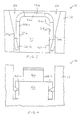
- connector 10 includes housing 12 comprised of electrically nonconductive material.
- Housing 12 defines a plurality of channels 14 opening into the upper surface of the housing, each channel being adapted for the receipt of contact member 16.
- Contact members 16 are electrically conductive and are formed with upper contact portion 16a, wing portion 16b, having wings 16b-1 and 16b-2, lower contact portion 16c and connecting portion 16d, which connects wing portion 16b and lower contact portion 16c.
- Housing 12 is open rearwardly for receipt of contact members 16.
- Wings 16b-1 and 16b-2 will be seen to progress through arcuate sections to extend orthogonally of the plane of the contact member, tapering downwardly to free ends which support retention barbs 16b-3 and 16b-4, which extend sidewardly outwardly of the planes of wings 16b-1 and 16b-2.
- Contact member portion 16c supports female contact member 18, one of its two mating contacts being indicated at 18a. Portion 16c and contact member 18 are mutually secured as indicated at 18b and 18c.
- slots 20 and 22 extend from wide openings at the rear of housing 12 to narrow width portions adjacent the front of housing 12, where they are bounded sidewardly by housing surface 22a and housing ledge surface 24a in the case of slot 20 and by housing surface 22b and housing ledge surface 24b in the case of slot 22.
- contact displacement plate 26 (Fig. 1), which has lower positioning fingers 26a, 26b.
- Contact members 16 are loaded into housing 12 rearwardly into channels 14 with wings 16b-1 and 16b-2 inserted into slots 20 and 22 at elevations such that all contact members can be engaged commonly atop contact portions 16a by plate fingers 26a, 26b.
- plate 26 With the contact members so retentively seated in the housing, plate 26 is placed such that plate fingers 26a, 26b. engage the tops of contact portions 16a and the plate is advanced downwardly.
- contact members 16 While retained in housing 12 by retention barbs 16b-3 and 16b-4, are forced further downwardly. Based on the geometry at hand, all tops of contact portions 16a are coplanar in disposition.
- the step of plate movement is such that plate 26 does not engage housing 12, whereby any warp or bowing in the housing does not affect coplanarity of the contact members.
Landscapes
- Engineering & Computer Science (AREA)
- Manufacturing & Machinery (AREA)
- Connector Housings Or Holding Contact Members (AREA)
- Coupling Device And Connection With Printed Circuit (AREA)
- Manufacturing Of Electrical Connectors (AREA)
Claims (6)
- Connecteur électrique (10) comprenant un boítier (12) formé d'un matériau électriquement isolant et d'éléments de contact (16) qui sont situés dans ledit boítier (12), lesdits éléments de contact (16) définissant des parties de contact (16a) et des moyens (16b-3, 16b-4) pour retenir lesdits éléments de contact (16) dans ledit boítier (12), ledit boítier (12) possédant une pluralité de canaux (14), un élément distinct faisant partie desdits éléments de contact (16) résidant dans chacun desdits canaux (14), et des première et seconde fentes (20, 22) en communication avec chacun desdits canaux, lesdits moyens (16b-3, 16b-4) de retenue des éléments de contact étant situés dans lesdites première et seconde fentes (20, 22) et coopérant d'une manière qui les retient engagés avec une paroi latérale de chacune desdites première et seconde fentes (20, 22) pur permettre un positionnement variable desdits moyens (16b-3, 16b-4) de retenue des éléments de contacts dans le boítier (12), ce qui a pour effet que lesdites parties de contact (16a) des éléments de contact peuvent être positionnées d'une manière coplanaire dans ledit boítier indépendamment d'une déformation présente dans le boítier.
- Connecteur électrique selon la revendication 1, dans lequel ladite partie de contact (16a) des éléments de contact est située sur une extrémité libre dudit élément de contact (16), ledit élément de contact (16) comprenant en outre une partie formant aile (16b) qui est distale par rapport à ladite extrémité libre des éléments de contact, ladite partie formant aile (16b) supportant lesdits moyens (16b-3, 16b-4) de retenue des éléments de contact sur leurs extrémités libres.
- Connecteur électrique selon la revendication 2, dans lequel lesdites parties formant ailes (16b) des éléments de contact incluent des première et seconde ailes (16b-1, 16b-2), lesdites première et seconde ailes (16b-1, 16b-2) étant situées respectivement dans lesdites première et seconde fentes (20, 22).
- Connecteur électrique selon la revendication 3, dans lequel lesdits moyens de retenue des éléments de contact comprennent des premier et second éléments en forme de barbes (16b-3, 16b-4) au niveau d'extrémités respectivement desdites première et seconde ailes (16b-1, 16b-2).
- Connecteur électrique selon l'une quelconque des revendications 2 à 4, dans lequel chacun desdits éléments de contact (16) comprend une autre partie de contact (16c) et une partie de connexion (16d) connectant ladite autre partie de contact (16c) à ladite partie formant aile (16b) de cet élément de contact.
- Connecteur électrique selon la revendication 5, dans lequel ladite autre partie de contact (16c) est disposée perpendiculairement à ladite partie de connexion (16d).
Applications Claiming Priority (2)
| Application Number | Priority Date | Filing Date | Title |
|---|---|---|---|
| US326177 | 1994-10-19 | ||
| US08/326,177 US5567185A (en) | 1994-10-19 | 1994-10-19 | Electrical connector and method of making same |
Publications (3)
| Publication Number | Publication Date |
|---|---|
| EP0708495A2 EP0708495A2 (fr) | 1996-04-24 |
| EP0708495A3 EP0708495A3 (fr) | 1997-10-29 |
| EP0708495B1 true EP0708495B1 (fr) | 2002-03-27 |
Family
ID=23271118
Family Applications (1)
| Application Number | Title | Priority Date | Filing Date |
|---|---|---|---|
| EP95307397A Expired - Lifetime EP0708495B1 (fr) | 1994-10-19 | 1995-10-18 | Connecteur électrique |
Country Status (5)
| Country | Link |
|---|---|
| US (1) | US5567185A (fr) |
| EP (1) | EP0708495B1 (fr) |
| CA (1) | CA2160624C (fr) |
| DE (1) | DE69526024T2 (fr) |
| ES (1) | ES2174903T3 (fr) |
Families Citing this family (7)
| Publication number | Priority date | Publication date | Assignee | Title |
|---|---|---|---|---|
| JPH1092532A (ja) * | 1996-09-17 | 1998-04-10 | Fujitsu Takamizawa Component Kk | コネクタとicカードコネクタ |
| US5984735A (en) * | 1998-08-28 | 1999-11-16 | Lucent Technologies Inc. | Material displacement type retention mechanism for connector terminals |
| US6302748B1 (en) * | 1999-12-22 | 2001-10-16 | Hon Hai Precision Ind. Co., Ltd. | Electrical connector having an improved housing with reliable contact receiving cavities |
| US6909049B2 (en) * | 2002-05-03 | 2005-06-21 | Fci Americas Technologies, Inc. | Electrical connector for angled conductors |
| US20090075528A1 (en) * | 2007-09-17 | 2009-03-19 | Thomas & Betts International, Inc. | 90-Degree ferrule and pin terminals |
| JP2010067432A (ja) * | 2008-09-10 | 2010-03-25 | Sumitomo Wiring Syst Ltd | コネクタ |
| CN113023343B (zh) * | 2021-03-03 | 2023-10-03 | 昆山市德来福工业自动化有限公司 | 一种定位爪裁切送料装置 |
Family Cites Families (12)
| Publication number | Priority date | Publication date | Assignee | Title |
|---|---|---|---|---|
| US3122604A (en) * | 1958-11-12 | 1964-02-25 | Steel City Electric Company | Ground clip for electrical outlet and switch boxes |
| US3535673A (en) * | 1968-03-08 | 1970-10-20 | Amp Inc | Electrical grounding terminal |
| US3686609A (en) * | 1971-04-13 | 1972-08-22 | Essex International Inc | Ground terminal |
| US4050777A (en) * | 1976-12-17 | 1977-09-27 | Walter Todd Peters | Solar energy reflecting apparatus with yieldably biased reflectors |
| GB2198599A (en) * | 1984-06-20 | 1988-06-15 | Trw Connectors | Insulation displacement connector |
| US4717354A (en) * | 1984-11-19 | 1988-01-05 | Amp Incorporated | Solder cup connector |
| JPH0416390Y2 (fr) * | 1986-04-30 | 1992-04-13 | ||
| US4909754A (en) * | 1988-11-25 | 1990-03-20 | Northern Telecom Limited | Connectors for telecommunications lines |
| US4860445A (en) * | 1989-02-09 | 1989-08-29 | Gte Products Corporation | Method of mounting electrical contacts in connector body |
| JP2542078Y2 (ja) * | 1989-07-14 | 1997-07-23 | 第一電子工業 株式会社 | 電気コネクタ |
| US5131872A (en) * | 1990-05-31 | 1992-07-21 | Amp Incorporated | Contact spring socket |
| JPH05299144A (ja) * | 1992-04-18 | 1993-11-12 | Molex Inc | 電気コネクタ |
-
1994
- 1994-10-19 US US08/326,177 patent/US5567185A/en not_active Expired - Lifetime
-
1995
- 1995-10-16 CA CA002160624A patent/CA2160624C/fr not_active Expired - Fee Related
- 1995-10-18 DE DE69526024T patent/DE69526024T2/de not_active Expired - Fee Related
- 1995-10-18 ES ES95307397T patent/ES2174903T3/es not_active Expired - Lifetime
- 1995-10-18 EP EP95307397A patent/EP0708495B1/fr not_active Expired - Lifetime
Also Published As
| Publication number | Publication date |
|---|---|
| US5567185A (en) | 1996-10-22 |
| EP0708495A3 (fr) | 1997-10-29 |
| CA2160624A1 (fr) | 1996-04-20 |
| DE69526024T2 (de) | 2002-08-29 |
| EP0708495A2 (fr) | 1996-04-24 |
| DE69526024D1 (de) | 2002-05-02 |
| CA2160624C (fr) | 2007-12-18 |
| ES2174903T3 (es) | 2002-11-16 |
Similar Documents
| Publication | Publication Date | Title |
|---|---|---|
| US9912106B2 (en) | Electrical connector having improved shielding shell | |
| US5535513A (en) | Method for making surface mountable connectors | |
| US3850497A (en) | Connector | |
| US4857017A (en) | Support device for wires in multi-contact connectors | |
| US5478253A (en) | Electrostatic discharge contacts for blind mating connectors | |
| US4824387A (en) | Biased floating connector | |
| US5161999A (en) | Surface mount electrical cohnnector and shield therefor | |
| US6071152A (en) | Electrical connector with inserted terminals | |
| US6050845A (en) | Electrical connector for terminating insulated conductors | |
| US6171126B1 (en) | Battery receptacle connector | |
| US5688143A (en) | Electrical connector for use with flexible printed circuit | |
| US6183315B1 (en) | Board-to-board connector assembly | |
| US4934943A (en) | Automated connector alignment assembly for connection of printed circuit boards | |
| US6210218B1 (en) | Electrical connector | |
| US5154634A (en) | Connector holding device | |
| US6482032B1 (en) | Electrical connector with board locks | |
| US6371790B1 (en) | Electrical assembly having anti-mismating device | |
| JPH08255658A (ja) | 雄型コンタクト、雌型コンタクトおよび一対の嵌合コンタクト | |
| US6926542B2 (en) | Electrical connector having improved terminals | |
| US4708416A (en) | Electrical connecting terminal for a connector | |
| US6478629B1 (en) | Audio jack having side mount grounding terminal | |
| US20040053540A1 (en) | Electrical connector and method of assembling the same | |
| US5131872A (en) | Contact spring socket | |
| US6890192B2 (en) | Sequential connection-type connector and additional contact used in the same | |
| US4372634A (en) | Tilt latch zero insertion force connector assembly |
Legal Events
| Date | Code | Title | Description |
|---|---|---|---|
| PUAI | Public reference made under article 153(3) epc to a published international application that has entered the european phase |
Free format text: ORIGINAL CODE: 0009012 |
|
| AK | Designated contracting states |
Kind code of ref document: A2 Designated state(s): BE CH DE ES FR GB IT LI LU NL SE |
|
| PUAL | Search report despatched |
Free format text: ORIGINAL CODE: 0009013 |
|
| AK | Designated contracting states |
Kind code of ref document: A3 Designated state(s): BE CH DE ES FR GB IT LI LU NL SE |
|
| 17P | Request for examination filed |
Effective date: 19980403 |
|
| 17Q | First examination report despatched |
Effective date: 19991026 |
|
| RTI1 | Title (correction) |
Free format text: ELECTRICAL CONNECTOR |
|
| GRAG | Despatch of communication of intention to grant |
Free format text: ORIGINAL CODE: EPIDOS AGRA |
|
| GRAG | Despatch of communication of intention to grant |
Free format text: ORIGINAL CODE: EPIDOS AGRA |
|
| GRAH | Despatch of communication of intention to grant a patent |
Free format text: ORIGINAL CODE: EPIDOS IGRA |
|
| GRAH | Despatch of communication of intention to grant a patent |
Free format text: ORIGINAL CODE: EPIDOS IGRA |
|
| REG | Reference to a national code |
Ref country code: GB Ref legal event code: IF02 |
|
| RAP1 | Party data changed (applicant data changed or rights of an application transferred) |
Owner name: THOMAS & BETTS CORPORATION |
|
| GRAA | (expected) grant |
Free format text: ORIGINAL CODE: 0009210 |
|
| AK | Designated contracting states |
Kind code of ref document: B1 Designated state(s): BE CH DE ES FR GB IT LI LU NL SE |
|
| REG | Reference to a national code |
Ref country code: CH Ref legal event code: EP |
|
| REG | Reference to a national code |
Ref country code: CH Ref legal event code: NV Representative=s name: BOVARD AG PATENTANWAELTE |
|
| REF | Corresponds to: |
Ref document number: 69526024 Country of ref document: DE Date of ref document: 20020502 |
|
| ET | Fr: translation filed | ||
| REG | Reference to a national code |
Ref country code: ES Ref legal event code: FG2A Ref document number: 2174903 Country of ref document: ES Kind code of ref document: T3 |
|
| PLBE | No opposition filed within time limit |
Free format text: ORIGINAL CODE: 0009261 |
|
| STAA | Information on the status of an ep patent application or granted ep patent |
Free format text: STATUS: NO OPPOSITION FILED WITHIN TIME LIMIT |
|
| 26N | No opposition filed |
Effective date: 20021230 |
|
| PGFP | Annual fee paid to national office [announced via postgrant information from national office to epo] |
Ref country code: LU Payment date: 20041001 Year of fee payment: 10 |
|
| PGFP | Annual fee paid to national office [announced via postgrant information from national office to epo] |
Ref country code: BE Payment date: 20041105 Year of fee payment: 10 |
|
| PG25 | Lapsed in a contracting state [announced via postgrant information from national office to epo] |
Ref country code: LU Free format text: LAPSE BECAUSE OF NON-PAYMENT OF DUE FEES Effective date: 20051031 Ref country code: BE Free format text: LAPSE BECAUSE OF NON-PAYMENT OF DUE FEES Effective date: 20051031 |
|
| BERE | Be: lapsed |
Owner name: *THOMAS & BETTS CORP. Effective date: 20051031 |
|
| PGFP | Annual fee paid to national office [announced via postgrant information from national office to epo] |
Ref country code: NL Payment date: 20071024 Year of fee payment: 13 Ref country code: ES Payment date: 20071026 Year of fee payment: 13 Ref country code: DE Payment date: 20071130 Year of fee payment: 13 |
|
| PGFP | Annual fee paid to national office [announced via postgrant information from national office to epo] |
Ref country code: CH Payment date: 20071030 Year of fee payment: 13 Ref country code: IT Payment date: 20071029 Year of fee payment: 13 |
|
| PGFP | Annual fee paid to national office [announced via postgrant information from national office to epo] |
Ref country code: SE Payment date: 20071029 Year of fee payment: 13 |
|
| PGFP | Annual fee paid to national office [announced via postgrant information from national office to epo] |
Ref country code: GB Payment date: 20071029 Year of fee payment: 13 Ref country code: FR Payment date: 20071017 Year of fee payment: 13 |
|
| REG | Reference to a national code |
Ref country code: CH Ref legal event code: PL |
|
| EUG | Se: european patent has lapsed | ||
| GBPC | Gb: european patent ceased through non-payment of renewal fee |
Effective date: 20081018 |
|
| NLV4 | Nl: lapsed or anulled due to non-payment of the annual fee |
Effective date: 20090501 |
|
| REG | Reference to a national code |
Ref country code: FR Ref legal event code: ST Effective date: 20090630 |
|
| PG25 | Lapsed in a contracting state [announced via postgrant information from national office to epo] |
Ref country code: NL Free format text: LAPSE BECAUSE OF NON-PAYMENT OF DUE FEES Effective date: 20090501 |
|
| PG25 | Lapsed in a contracting state [announced via postgrant information from national office to epo] |
Ref country code: IT Free format text: LAPSE BECAUSE OF NON-PAYMENT OF DUE FEES Effective date: 20081018 Ref country code: DE Free format text: LAPSE BECAUSE OF NON-PAYMENT OF DUE FEES Effective date: 20090501 |
|
| PG25 | Lapsed in a contracting state [announced via postgrant information from national office to epo] |
Ref country code: LI Free format text: LAPSE BECAUSE OF NON-PAYMENT OF DUE FEES Effective date: 20081031 Ref country code: FR Free format text: LAPSE BECAUSE OF NON-PAYMENT OF DUE FEES Effective date: 20081031 Ref country code: CH Free format text: LAPSE BECAUSE OF NON-PAYMENT OF DUE FEES Effective date: 20081031 |
|
| PG25 | Lapsed in a contracting state [announced via postgrant information from national office to epo] |
Ref country code: GB Free format text: LAPSE BECAUSE OF NON-PAYMENT OF DUE FEES Effective date: 20081018 |
|
| REG | Reference to a national code |
Ref country code: ES Ref legal event code: FD2A Effective date: 20081020 |
|
| PG25 | Lapsed in a contracting state [announced via postgrant information from national office to epo] |
Ref country code: ES Free format text: LAPSE BECAUSE OF NON-PAYMENT OF DUE FEES Effective date: 20081020 |
|
| PG25 | Lapsed in a contracting state [announced via postgrant information from national office to epo] |
Ref country code: SE Free format text: LAPSE BECAUSE OF NON-PAYMENT OF DUE FEES Effective date: 20081019 |