EP0708513B1 - Cellule avec disjoncteur auto-sectionneur - Google Patents
Cellule avec disjoncteur auto-sectionneur Download PDFInfo
- Publication number
- EP0708513B1 EP0708513B1 EP95402291A EP95402291A EP0708513B1 EP 0708513 B1 EP0708513 B1 EP 0708513B1 EP 95402291 A EP95402291 A EP 95402291A EP 95402291 A EP95402291 A EP 95402291A EP 0708513 B1 EP0708513 B1 EP 0708513B1
- Authority
- EP
- European Patent Office
- Prior art keywords
- support beam
- switchgear according
- portions
- rotating
- shaft
- Prior art date
- Legal status (The legal status is an assumption and is not a legal conclusion. Google has not performed a legal analysis and makes no representation as to the accuracy of the status listed.)
- Expired - Lifetime
Links
- 229910001220 stainless steel Inorganic materials 0.000 claims abstract description 4
- 239000010935 stainless steel Substances 0.000 claims abstract description 4
- 239000002184 metal Substances 0.000 claims description 5
- 229910052751 metal Inorganic materials 0.000 claims description 5
- XEEYBQQBJWHFJM-UHFFFAOYSA-N Iron Chemical compound [Fe] XEEYBQQBJWHFJM-UHFFFAOYSA-N 0.000 description 6
- 235000000396 iron Nutrition 0.000 description 4
- 229910052742 iron Inorganic materials 0.000 description 3
- 210000000056 organ Anatomy 0.000 description 3
- 239000012212 insulator Substances 0.000 description 2
- 238000004519 manufacturing process Methods 0.000 description 2
- 238000010276 construction Methods 0.000 description 1
- 238000006073 displacement reaction Methods 0.000 description 1
- 238000012423 maintenance Methods 0.000 description 1
- 238000004021 metal welding Methods 0.000 description 1
- 230000005405 multipole Effects 0.000 description 1
Images


Classifications
-
- H—ELECTRICITY
- H02—GENERATION; CONVERSION OR DISTRIBUTION OF ELECTRIC POWER
- H02B—BOARDS, SUBSTATIONS OR SWITCHING ARRANGEMENTS FOR THE SUPPLY OR DISTRIBUTION OF ELECTRIC POWER
- H02B13/00—Arrangement of switchgear in which switches are enclosed in, or structurally associated with, a casing, e.g. cubicle
- H02B13/02—Arrangement of switchgear in which switches are enclosed in, or structurally associated with, a casing, e.g. cubicle with metal casing
-
- H—ELECTRICITY
- H02—GENERATION; CONVERSION OR DISTRIBUTION OF ELECTRIC POWER
- H02B—BOARDS, SUBSTATIONS OR SWITCHING ARRANGEMENTS FOR THE SUPPLY OR DISTRIBUTION OF ELECTRIC POWER
- H02B11/00—Switchgear having carriage withdrawable for isolation
- H02B11/12—Switchgear having carriage withdrawable for isolation with isolation by horizontal withdrawal
- H02B11/173—Switchgear having carriage withdrawable for isolation with isolation by horizontal withdrawal drawer type
-
- H—ELECTRICITY
- H01—ELECTRIC ELEMENTS
- H01H—ELECTRIC SWITCHES; RELAYS; SELECTORS; EMERGENCY PROTECTIVE DEVICES
- H01H33/00—High-tension or heavy-current switches with arc-extinguishing or arc-preventing means
- H01H33/02—Details
Definitions
- the present invention relates to a cell medium voltage fitted with a self-disconnecting circuit breaker.
- a multi-pole self-disconnecting circuit breaker includes, for each pole, an insulating envelope enclosing a cut-off device such as a light bulb empty, the envelope having at one end a first contact connected to a first terminal of the organ cutout and intended to cooperate with a bar of a game bars, and at a second end a second contact connected to a second terminal of the breaking device and intended to cooperate with a cable from a set of cables, the envelopes of different poles being attached to the same metal profile along which a tree of maneuver common to the poles which is actuated by a control contained in a box secured to the profile, the profile being actuated in rotation to ensure the device sectioning function.
- a cut-off device such as a light bulb empty
- a medium voltage cubicle including a self-disconnecting circuit breaker placed in a sliding drawer in a box with support insulators for a game bars and support insulators for a cables, said circuit breaker being able, in the "off" position service ", and after a 90 degree rotation of all the poles, take place entirely in the drawer which can then optionally be removed from the box.
- An object of the present invention is to define a industrial embodiment of the cell drawer, simple and economical construction, and ensuring perfect operational safety and security for the maintenance staff.
- Another object of the invention is to specify the manual or automatic means allowing the rotation of all the poles for a racking-in operation or removal.
- the subject of the invention is a medium cell voltage including a self-disconnecting circuit breaker comprising for each pole, an insulating envelope containing cut-off devices, the different envelopes being carried by a common support beam attached to a control box for ordering simultaneous pole breaking devices, each pole being connected on the one hand by first connectors to a busbars and secondly by second connectors to a set of cables, the circuit breaker can be taken out of service by rotation of the support beam and, in the out of service position, be housed in a drawer which can be removed from the cell, characterized in that the drawer consists of a chassis formed by a bent stainless steel tube.
- the tube section is square, rectangular or circular.
- the chassis includes two horizontal portions parallel equipped with casters.
- Said horizontal portions are extended to a first end by two first portions vertical joined by a first horizontal portion bearing a first shaft element for the support beam.
- the horizontal portions are extended to a second end with second vertical portions to which U-shaped irons are attached.
- the U-shaped irons are connected by a first plate metal, located on the rear side of the cell, and a second plate, a second shaft element for the rotation of the beam passing through said plates.
- One of the second vertical portions is extended by portions forming so as to form an almost closed quadrilateral in a vertical plane parallel to the horizontal portions.
- a device for the rotation of the support beam is fixed on the one hand audited portions forming an almost closed quadrilateral and on the other hand to a second metal plate fixed to said U-shaped iron.
- the device for the rotation of the support beam comprises a first shaft of which the end can receive a crank and the other end rotates a second threaded shaft fitted with a nut having tenons and subject to stay fixed in rotation so that the rotation of the second shaft causes the translational movement of tenons, said tenons engaging in a fork secured to the support beam and the housing control and articulated to the second shaft element, the translational movement of the pins causing the fork rotation.
- the cell includes an electric motor for training the first tree.
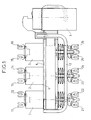
- Figure 1 shows, in elevation, a drawer of a medium voltage cubicle with self-disconnecting circuit breaker.
- the cell is represented from the side, its face front being to the right of the figure and the rear face to left of the figure.
- Figure 2 is the top view corresponding.
- the drawer in which the poles are placed 1 to 3 and the common support beam 4 consists of a chassis consisting of a curved tube 7, preferably in stainless steel; advantageously the chassis is consisting of a single tube.
- the tube section is square, which facilitates fixing the various organs necessary but it may alternatively be rectangular or circular.
- Figures 3 to 5 explain the shape of the tubular chassis.
- Figures 3 and 4 show, at reduced scale compared to figs 1 and 2, the chassis in the respective positions of FIGS. 1 and 2;
- Figure 5 shows, on the same scale as the figures 3 and 4, the chassis seen at the end.
- the chassis has two parallel portions horizontal 7A and 7B of the same length, constituting the bottom of the chassis, and in which are placed casters 31 to 34. These casters allow the whole tripolar to roll in horizontal translation at inside the cell on rails or slides not shown.
- the tube has two portions vertical 7C and 7D of equal heights and connected by a horizontal portion 7E.
- portion 7E In the middle of portion 7E is fixed a first horizontal shaft element 36 to which the pole support beam 5 will be articulated.
- the portion 7B of the chassis folds into a 7G vertical portion at which is fixed, preferably by riveting, a U-shaped iron 37 (or any appropriate angle element).
- the other portion 7A extends, front side of the cell, by a portion vertical 7H itself continued, in the same plane vertical, by a horizontal portion 7J followed by a vertical portion 7K towards the bottom of the drawer and finally ended with a short horizontal portion 7L in direction of the back of the drawer. So the portions 7H, 7J, 7K and 7 L draw a rectangle almost closed in a vertical plane parallel to portions 7A and 7B.
- a U-shaped iron 38 (or analogous element performing the same function); the irons 37 and 38 allow the attachment of a first plate 39, called back plate because it is located, by compared to the second plate described below towards the back of the drawer.
- This plate is mainly used for stiffening the chassis and maintaining the second shaft element for the beam, described later.
- Withdrawal can be carried out manually or at using an electric motor.
- the engine is referenced 42 in FIGS. 7 and 8, but we will first describe the elements for the manual removal.
- These include a tree 43 provided with an end allowing a connection with an operating crank. At the other end, the tree 43 carries a bevel gear 44 meshing on a pinion 45 disposed at one end of a shaft 46 disposed parallel to the plate 40 in a horizontal plane.
- the other end of the shaft is threaded and carries a nut 47 provided with pins 48A and 48B; the nut is subject to remain fixed in rotation so that a rotational movement of the shaft 46 communicates with the nut 47, so tenons 48A and 48B, a movement of translation.
- a stop 49 also serving as a bearing for the shaft 46, limits the travel of the nut 47.
- the shaft 43 can be driven by the motor 42 whose shaft carries a pinion 50 cooperating with a ring gear 51 wedged on the tree 43.
- Figure 9 shows in elevation the support beam 4 showing a second shaft element 60 for the rotation of the support beam.
- a fork comprising two parallel plates 61 and 62 is secured by brackets 63 and 64 to the housing of operation 6 and to the support beam 4 (see FIGS. 9 and 10).
- the pins 48A and 48B of the nut 47 engage in notches 65 and 66 of plates 61 and 62, so that the translational movement of the nut 47 produces a rotational movement of the circuit breaker assembly and the operating box 6.
- the invention is easy to implement and economical and applies to all ranges of cells medium voltage.
Landscapes
- Engineering & Computer Science (AREA)
- Power Engineering (AREA)
- Driving Mechanisms And Operating Circuits Of Arc-Extinguishing High-Tension Switches (AREA)
- Preparation Of Compounds By Using Micro-Organisms (AREA)
- Refuge Islands, Traffic Blockers, Or Guard Fence (AREA)
- Secondary Cells (AREA)
- Control Of Eletrric Generators (AREA)
- Patch Boards (AREA)
- Switch Cases, Indication, And Locking (AREA)
- Cable Accessories (AREA)
- Input Circuits Of Receivers And Coupling Of Receivers And Audio Equipment (AREA)
Applications Claiming Priority (2)
| Application Number | Priority Date | Filing Date | Title |
|---|---|---|---|
| FR9412354A FR2725843B1 (fr) | 1994-10-17 | 1994-10-17 | Cellule avec disjoncteur auto-sectionneur |
| FR9412354 | 1994-10-17 |
Publications (2)
| Publication Number | Publication Date |
|---|---|
| EP0708513A1 EP0708513A1 (fr) | 1996-04-24 |
| EP0708513B1 true EP0708513B1 (fr) | 1999-03-03 |
Family
ID=9467918
Family Applications (1)
| Application Number | Title | Priority Date | Filing Date |
|---|---|---|---|
| EP95402291A Expired - Lifetime EP0708513B1 (fr) | 1994-10-17 | 1995-10-13 | Cellule avec disjoncteur auto-sectionneur |
Country Status (6)
| Country | Link |
|---|---|
| EP (1) | EP0708513B1 (da) |
| AT (1) | ATE177256T1 (da) |
| DE (1) | DE69508032T2 (da) |
| DK (1) | DK0708513T3 (da) |
| ES (1) | ES2130551T3 (da) |
| FR (1) | FR2725843B1 (da) |
Families Citing this family (2)
| Publication number | Priority date | Publication date | Assignee | Title |
|---|---|---|---|---|
| FR2789798B1 (fr) * | 1999-02-15 | 2004-01-09 | Alstom | Module de disjoncteur auto-sectionneur, moyenne tension et poste de distribution d'energie correspondant |
| CN120854214B (zh) * | 2025-09-24 | 2026-02-10 | 君易电力科技有限公司 | 一种一二次融合成套柱上断路器 |
Family Cites Families (3)
| Publication number | Priority date | Publication date | Assignee | Title |
|---|---|---|---|---|
| FR1231725A (fr) * | 1959-04-11 | 1960-10-03 | Interrupteur haute tension pour cabine préfabriquée | |
| DE1515742A1 (de) * | 1965-12-11 | 1969-11-20 | Felten & Guilleaume Schaltanl | Um eine horizontale Achse schwenkbar angeordneter Leistungsschalter fuer Innenraumanlagen mit Doppelsammelschienensystem |
| FR2683939B1 (fr) * | 1991-11-20 | 1993-12-31 | Gec Alsthom Sa | Disjoncteur auto-sectionneur a moyenne tension et application a une cellule et a un poste a moyenne tension. |
-
1994
- 1994-10-17 FR FR9412354A patent/FR2725843B1/fr not_active Expired - Fee Related
-
1995
- 1995-10-13 DK DK95402291T patent/DK0708513T3/da active
- 1995-10-13 AT AT95402291T patent/ATE177256T1/de not_active IP Right Cessation
- 1995-10-13 EP EP95402291A patent/EP0708513B1/fr not_active Expired - Lifetime
- 1995-10-13 ES ES95402291T patent/ES2130551T3/es not_active Expired - Lifetime
- 1995-10-13 DE DE69508032T patent/DE69508032T2/de not_active Expired - Fee Related
Also Published As
| Publication number | Publication date |
|---|---|
| DK0708513T3 (da) | 1999-09-27 |
| ATE177256T1 (de) | 1999-03-15 |
| ES2130551T3 (es) | 1999-07-01 |
| DE69508032D1 (de) | 1999-04-08 |
| FR2725843B1 (fr) | 1996-12-20 |
| FR2725843A1 (fr) | 1996-04-19 |
| DE69508032T2 (de) | 1999-08-12 |
| EP0708513A1 (fr) | 1996-04-24 |
Similar Documents
| Publication | Publication Date | Title |
|---|---|---|
| EP0986153B1 (fr) | Appareillage électrique de coupure comportant un disjoncteur débrochable et des indicateurs de la position du disjoncteur dans son châssis | |
| EP0543683B1 (fr) | Disjoncteur auto-sectionneur à moyenne tension et application à une cellule et à un poste à moyenne tension | |
| EP0543682B1 (fr) | Disjoncteur auto-sectionneur à hexafluorure de soufre et applications aux cellules et aux postes et sous-stations préfabriqués | |
| EP0610143A1 (fr) | Dispositif de condamnation mécanique et électrique d'un bloc de télécommande pour disjoncteur modulaire | |
| EP0708513B1 (fr) | Cellule avec disjoncteur auto-sectionneur | |
| FR2575340A1 (fr) | Systeme et colonne de distribution pour appareils interrupteurs | |
| FR2691009A1 (fr) | Sectionneur à ouverture verticale et colonne oscillante. | |
| FR2782579A1 (fr) | Appareillage electrique de coupure comportant un disjoncteur embrochable et un dispositif indiquant l'etat du disjoncteur | |
| FR2744284A1 (fr) | Interrupteur ou disjoncteur multipolaire moyenne tension | |
| FR2647030A1 (fr) | Melangeur avec ecran mobile de protection | |
| EP0352149A1 (fr) | Dispositif de support pour appareils électriques | |
| BE880186A (fr) | Dispositif de recolte de pieces de monnaie | |
| FR2458505A3 (fr) | Dispositif de levage perfectionne en particulier pour la manutention de conteneurs | |
| EP0620625B1 (fr) | Châssis de débrochage pour un disjoncteur | |
| EP0731481A1 (fr) | Disjoncteur auto-sectionneur à sectionnement auto-verrouillé en position fermée des chambres de coupure | |
| FR2688339A1 (fr) | Disjoncteur auto-sectionneur a intensite nominale elevee et application a une cellule et a un poste a moyenne tension. | |
| FR2581242A1 (fr) | Dispositif de commande electrique adaptable a un dispositif de commutation a deux etats | |
| FR2541257A1 (fr) | Dispositif tendeur pour le transport de matieres en forme de bande | |
| EP0707330B1 (fr) | Disjoncteur auto-sectionneur | |
| FR2614514A1 (fr) | Support mobile destine a etre monte dans un meuble de cuisine pour permettre le rangement et/ou l'utilisation d'un appareil electromenager | |
| EP0750328B1 (fr) | Interrupteur auto-sectionneur | |
| FR2815476A1 (fr) | Dispositif de deplacement d'un mat mobile destine au support d'au moins une antenne | |
| CA2243612C (fr) | Sectionneur hybride de ligne et de mise a la terre | |
| FR3050330A1 (fr) | Cellule electrique a appareil debrochable comprenant un volet de protection | |
| FR2798011A1 (fr) | Poste a double jeu de barres et appareil de coupure et d'aiguillage destine a etre utilise dans ce poste |
Legal Events
| Date | Code | Title | Description |
|---|---|---|---|
| PUAI | Public reference made under article 153(3) epc to a published international application that has entered the european phase |
Free format text: ORIGINAL CODE: 0009012 |
|
| AK | Designated contracting states |
Kind code of ref document: A1 Designated state(s): AT BE CH DE DK ES GB IT LI NL SE |
|
| 17P | Request for examination filed |
Effective date: 19960912 |
|
| GRAG | Despatch of communication of intention to grant |
Free format text: ORIGINAL CODE: EPIDOS AGRA |
|
| 17Q | First examination report despatched |
Effective date: 19980622 |
|
| GRAG | Despatch of communication of intention to grant |
Free format text: ORIGINAL CODE: EPIDOS AGRA |
|
| GRAH | Despatch of communication of intention to grant a patent |
Free format text: ORIGINAL CODE: EPIDOS IGRA |
|
| GRAH | Despatch of communication of intention to grant a patent |
Free format text: ORIGINAL CODE: EPIDOS IGRA |
|
| GRAA | (expected) grant |
Free format text: ORIGINAL CODE: 0009210 |
|
| AK | Designated contracting states |
Kind code of ref document: B1 Designated state(s): AT BE CH DE DK ES GB IT LI NL SE |
|
| REF | Corresponds to: |
Ref document number: 177256 Country of ref document: AT Date of ref document: 19990315 Kind code of ref document: T |
|
| REG | Reference to a national code |
Ref country code: CH Ref legal event code: EP |
|
| REG | Reference to a national code |
Ref country code: CH Ref legal event code: NV Representative=s name: CABINET ROLAND NITHARDT CONSEILS EN PROPRIETE INDU |
|
| REF | Corresponds to: |
Ref document number: 69508032 Country of ref document: DE Date of ref document: 19990408 |
|
| GBT | Gb: translation of ep patent filed (gb section 77(6)(a)/1977) |
Effective date: 19990423 |
|
| REG | Reference to a national code |
Ref country code: ES Ref legal event code: FG2A Ref document number: 2130551 Country of ref document: ES Kind code of ref document: T3 |
|
| PGFP | Annual fee paid to national office [announced via postgrant information from national office to epo] |
Ref country code: SE Payment date: 19990920 Year of fee payment: 5 Ref country code: DK Payment date: 19990920 Year of fee payment: 5 |
|
| PGFP | Annual fee paid to national office [announced via postgrant information from national office to epo] |
Ref country code: NL Payment date: 19990923 Year of fee payment: 5 Ref country code: AT Payment date: 19990923 Year of fee payment: 5 |
|
| REG | Reference to a national code |
Ref country code: DK Ref legal event code: T3 |
|
| PGFP | Annual fee paid to national office [announced via postgrant information from national office to epo] |
Ref country code: BE Payment date: 19990929 Year of fee payment: 5 |
|
| PLBE | No opposition filed within time limit |
Free format text: ORIGINAL CODE: 0009261 |
|
| STAA | Information on the status of an ep patent application or granted ep patent |
Free format text: STATUS: NO OPPOSITION FILED WITHIN TIME LIMIT |
|
| 26N | No opposition filed | ||
| PG25 | Lapsed in a contracting state [announced via postgrant information from national office to epo] |
Ref country code: DK Free format text: LAPSE BECAUSE OF NON-PAYMENT OF DUE FEES Effective date: 20001013 Ref country code: AT Free format text: LAPSE BECAUSE OF NON-PAYMENT OF DUE FEES Effective date: 20001013 |
|
| PG25 | Lapsed in a contracting state [announced via postgrant information from national office to epo] |
Ref country code: SE Free format text: THE PATENT HAS BEEN ANNULLED BY A DECISION OF A NATIONAL AUTHORITY Effective date: 20001030 |
|
| PG25 | Lapsed in a contracting state [announced via postgrant information from national office to epo] |
Ref country code: BE Free format text: LAPSE BECAUSE OF NON-PAYMENT OF DUE FEES Effective date: 20001031 |
|
| BERE | Be: lapsed |
Owner name: S.A. GEC ALSTHOM T ET D Effective date: 20001031 |
|
| PG25 | Lapsed in a contracting state [announced via postgrant information from national office to epo] |
Ref country code: NL Free format text: LAPSE BECAUSE OF NON-PAYMENT OF DUE FEES Effective date: 20010501 |
|
| REG | Reference to a national code |
Ref country code: DK Ref legal event code: EBP |
|
| EUG | Se: european patent has lapsed |
Ref document number: 95402291.9 |
|
| NLV4 | Nl: lapsed or anulled due to non-payment of the annual fee |
Effective date: 20010501 |
|
| REG | Reference to a national code |
Ref country code: GB Ref legal event code: IF02 |
|
| PGFP | Annual fee paid to national office [announced via postgrant information from national office to epo] |
Ref country code: ES Payment date: 20051007 Year of fee payment: 11 |
|
| PGFP | Annual fee paid to national office [announced via postgrant information from national office to epo] |
Ref country code: GB Payment date: 20051012 Year of fee payment: 11 |
|
| PG25 | Lapsed in a contracting state [announced via postgrant information from national office to epo] |
Ref country code: IT Free format text: LAPSE BECAUSE OF NON-PAYMENT OF DUE FEES;WARNING: LAPSES OF ITALIAN PATENTS WITH EFFECTIVE DATE BEFORE 2007 MAY HAVE OCCURRED AT ANY TIME BEFORE 2007. THE CORRECT EFFECTIVE DATE MAY BE DIFFERENT FROM THE ONE RECORDED. Effective date: 20051013 |
|
| PGFP | Annual fee paid to national office [announced via postgrant information from national office to epo] |
Ref country code: CH Payment date: 20051025 Year of fee payment: 11 |
|
| PGFP | Annual fee paid to national office [announced via postgrant information from national office to epo] |
Ref country code: DE Payment date: 20051026 Year of fee payment: 11 |
|
| REG | Reference to a national code |
Ref country code: CH Ref legal event code: PFA Owner name: ALSTOM T & D S.A. Free format text: GEC ALSTHOM T ET D SA#38, AVENUE KLEBER#75016 PARIS (FR) -TRANSFER TO- ALSTOM T & D S.A.#25, AVENUE KLEBER#75116 PARIS (FR) |
|
| PG25 | Lapsed in a contracting state [announced via postgrant information from national office to epo] |
Ref country code: LI Free format text: LAPSE BECAUSE OF NON-PAYMENT OF DUE FEES Effective date: 20061031 Ref country code: CH Free format text: LAPSE BECAUSE OF NON-PAYMENT OF DUE FEES Effective date: 20061031 |
|
| PG25 | Lapsed in a contracting state [announced via postgrant information from national office to epo] |
Ref country code: DE Free format text: LAPSE BECAUSE OF NON-PAYMENT OF DUE FEES Effective date: 20070501 |
|
| REG | Reference to a national code |
Ref country code: CH Ref legal event code: PL |
|
| GBPC | Gb: european patent ceased through non-payment of renewal fee |
Effective date: 20061013 |
|
| PG25 | Lapsed in a contracting state [announced via postgrant information from national office to epo] |
Ref country code: GB Free format text: LAPSE BECAUSE OF NON-PAYMENT OF DUE FEES Effective date: 20061013 |
|
| REG | Reference to a national code |
Ref country code: ES Ref legal event code: FD2A Effective date: 20061014 |
|
| PG25 | Lapsed in a contracting state [announced via postgrant information from national office to epo] |
Ref country code: ES Free format text: LAPSE BECAUSE OF NON-PAYMENT OF DUE FEES Effective date: 20061014 |