EP0708559B1 - Sicherungssystem für die Spannungsversorgung in einem Fernsehkabelsystem - Google Patents
Sicherungssystem für die Spannungsversorgung in einem Fernsehkabelsystem Download PDFInfo
- Publication number
- EP0708559B1 EP0708559B1 EP95307383A EP95307383A EP0708559B1 EP 0708559 B1 EP0708559 B1 EP 0708559B1 EP 95307383 A EP95307383 A EP 95307383A EP 95307383 A EP95307383 A EP 95307383A EP 0708559 B1 EP0708559 B1 EP 0708559B1
- Authority
- EP
- European Patent Office
- Prior art keywords
- trunk
- supply
- relay
- voltage
- switching means
- Prior art date
- Legal status (The legal status is an assumption and is not a legal conclusion. Google has not performed a legal analysis and makes no representation as to the accuracy of the status listed.)
- Expired - Lifetime
Links
Images


Classifications
-
- H—ELECTRICITY
- H04—ELECTRIC COMMUNICATION TECHNIQUE
- H04N—PICTORIAL COMMUNICATION, e.g. TELEVISION
- H04N7/00—Television systems
- H04N7/10—Adaptations for transmission by electrical cable
- H04N7/102—Circuits therefor, e.g. noise reducers, equalisers, amplifiers
-
- H—ELECTRICITY
- H02—GENERATION; CONVERSION OR DISTRIBUTION OF ELECTRIC POWER
- H02J—ELECTRIC POWER NETWORKS; CIRCUIT ARRANGEMENTS OR SYSTEMS FOR SUPPLYING OR DISTRIBUTING ELECTRIC POWER; SYSTEMS FOR STORING ELECTRIC ENERGY
- H02J9/00—Circuit arrangements for emergency or stand-by power supply, e.g. for emergency lighting
- H02J9/04—Circuit arrangements for emergency or stand-by power supply, e.g. for emergency lighting in which the distribution system is disconnected from the normal source and connected to a standby source
- H02J9/06—Circuit arrangements for emergency or stand-by power supply, e.g. for emergency lighting in which the distribution system is disconnected from the normal source and connected to a standby source with automatic change-over, e.g. UPS systems
- H02J9/062—Circuit arrangements for emergency or stand-by power supply, e.g. for emergency lighting in which the distribution system is disconnected from the normal source and connected to a standby source with automatic change-over, e.g. UPS systems for AC powered loads
Definitions
- the present invention relates to a back-up system for the supply of electric voltage to main and secondary amplifiers in television cable systems in case of an electricity fault.
- US-A-3 909 560 discloses a method and system for providing DC power to booster amplifiers in HF cable networks.
- the usual television cable system comprises main lines (called “trunk” lines) each one extending from the television station.
- Each trunk line consists of a cable connecting several main amplifiers (called “trunks”) arranged in a so called cascade manner.
- Each trunk amplifies the signals coming from the station towards the next trunk.
- each trunk transfers said signals to secondary amplifiers lex (line extender), if any, branched out of it.
- Voltage is supplied to the trunk and to the lex by an electric source being located near the trunk and feeding the trunk.
- the voltage is suitably supplied via a local power insert (L.P.I.).
- the electric source is preferably the general electric net form which the voltage is transformed by a transformer to the required voltage.
- the lex if any, is supplied with voltage, preferably of 50-68 V, by a voltage bridge via co-axial cables extending from the trunk to the branches of lexes.
- the above system will be called herein "television cable system”.
- the trunks in this system are located about 500-900 m from each other.
- the electric source is located about 2 to 35 m from the appropriate trunk.
- each main trunk amplifier comprising switching means, characterized in that; the switching means is switchable between two AC voltage sources, a first AC source being a local power supply source and a second AC source being the electricity supply to a neighbouring trunk amplifier, the switching means being actuated when an electricity fault occurs in the local source of electricity to the trunk amplifier thereby switching the source of electricity to the trunk amplifier to the second AC supply.
- the switching means are automatically actuated in case that there occurs a fault of electricity in one of the electric sources supplying electric current to the trunk.
- voltage is switched on the main line between two amplifiers. This is preferably achieved by inserting an additional fuse to the L.P.I.
- the L.P.I. may then supply feeding voltage to the near trunk and back-up voltage to the previous or following trunk of the cascade.
- the switching means may be a relay; an element switching current by voltage or outer current (called a "triak” which may be composed of 2 (SCR) units); a transistor; etc.
- the preferred switching means is an AC relay working preferably on 48-68 V.
- the advantage of using an AC relay is that the voltage is constant and there is no difference between the "in” and the "out” voltage.
- a DC relay connected to a diode bridge may also be used.
- the present invention will be illustrated herein especially with reference to the switching means being an AC relay, however as is readily understood it is not restricted thereto.
- the switching means are advantageously located within the trunk and connected to an in/out supply socket, to a fuse terminal (in case of a MAGNAVOX® trunk) or to a voltage supply selecting socket (in case of a JERROLD® trunk). It is readily understood that the present invention is not restricted to said trunks and that any other commercially available trunk may be used.
- the kind of connection depends on the switching means and to the kind of trunk amplifier being used.
- An additional switching means may be located within the trunk or be located thereto by a bridging cable.
- the AC relay is suitably built in such a manner that it is actuated by a voltage of 50 V. All the time that the voltage is above 50 V the relay is on "on", i.e. the voltage supplied originates from the original electric source. The moment the voltage is below 50 V the relay is on “off” and electricity is supplied from the back-up electric source and the trunk and the secondary amplifiers are fed by the back-up electric source. The moment the electric fault has been repaired the relay returns to the "on" position and voltage is supplied from the original electric source.
- the relay may also be connected in the reverse direction and then it works from the last trunk of the cascade towards the first one.
- system 1 should also enable the back-up of the last trunk of the cascade the system is provided with 2 two-way back-up units, said units being located outside and between the last two trunks of the cascade, each unit being connected via an L.P.I to a separate trunk and to a separate electric source, said units operating in opposite directions one to another, each unit comprising an ignition circuit and a maintenance circuit.
- the ignition circuit advantageously comprises a diode and a relay.
- the maintenance circuit advantageously comprises a transformer, diodes and a relay.
- the relay may be common to both circuits.
- the L.P.I is advantageously a separate part. However, if desired, the two way back-up unit and the L.P.I. may be built as an integral part.
- two-way back-up units are inserted only between the last two trunks of the cascade where they are necessary if the last trunk should be backed-up.
- the two-way back-up units may in addition be inserted between two other or more trunks of the cascade.
- the two-way back up unit operates as follows:
- the ignition circuit in the two-way back-up unit being connected to the adjoining trunk is ignited and the maintenance circuit of said unit is actuated, after a certain delay, e.g. about 1 sec. and then voltage is supplied to the trunk where the fault occurs.
- a certain delay e.g. about 1 sec. and then voltage is supplied to the trunk where the fault occurs.
- the electric source is preferably one which, when no voltage is supplied from the general network to the inlet thereof, is disconnected from the cable system. Otherwise a relay has to be inserted at the inlet or the two-way back-up unit.
- the above two-way back-up unit can be utilised not only as part of system 1 of the present invention but also for other purposes. Thus it may be utilised for switching voltage when the customer uses above a certain wattage and the drop of said wattage below a certain minimum causes disconnection of electricity. Thus it may be used for an instrument protecting against electrification; for protecting electrical instruments, etc.
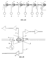
- the system shown in Fig. 1a comprises cable 1 originating in the television station (not shown) connecting trunks A, B, C, D, E and F in a cascade to each other.
- Each of said trunks comprise a relay 2.
- L.P.I. units 3 being connected to electric sources A' to E', respectively.
- the back-up units between trunks A to E are one-way back-up units.
- L.P.I. units 4 and 4' being connected via two-way back-up units 5 and 5' to electric sources E" and F', respectively. This constitutes a so-called two-way back up unit.
- Trunk B (by way of example only) comprising relay 2.
- Trunk B is connected via fuses F1, F2 and F3 by cables C', C" and C"', respectively, to lexes 6 (only one being referenced).
- Electric source 7 is connected by cable 8 to L.P.I. 9 which is in turn connected to relay 2 located in trunk B.
- Fig. 1c The system illustrated in Fig. 1c is the same as that shown in Fig. 1b with the addition of an additional electric source 7', line 8' and L.P.I. 9'.
- Electric source 7 supplies voltage to the adjoining trunk and electric source 7' supplies back-up voltage to the preceding trunk in the cascade.
- the system illustrated in Fig. 1d shows OPT receiver 10 connected to several lexes 6' and connected by cables C' and C" to trunk amplifiers 11 and 12.
- Electric source 7 supplies normal power to trunk amplifier 11 including lexes 5 connected to a bridger. Electric source 7 supplies also back-up power to OPT receiver 10 and to all lexes 6' connected thereto.
- L.P.I 9 is connected by 2 fuses providing voltage to trunk amplifier 11 and back-up voltage to OPT receiver 10 and to all lexes 6' connected thereto.
- L.P.I. 9' is used for forwarding back-up voltage to external back-up unit 14.
- L.P.I. 9" forwards power to OPT 10 and to all lexes 6' connected thereto.
- Electric source 8 is connected to external back-up unit 14 at the normal power input side.
- L.P.I. 9'" Is connected by one fuse to supply voltage to trunk 12 and lexes 6 connected thereto.
- Optic fiber 15 supplies signals to OPT receiver 10. In order to avoid overload in the course of the back-up time. It is possible to add an additional electric source for backing-up only in the same manner as in Fig. 1c.
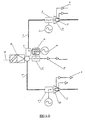
- Figs. 2a and 2b shows an one-way back-up unit for trunks A to E in on and off position, respectively.
- Fig. 2c shows the on position for an one-way back up unit for amplifier F, i.e. the last trunk in the cascade.
- the two-way unit illustrated in Fig. 3a comprises :
- Fig. 3b shows trunks E and F each comprising a relay 2.
- Trunk E is connected on one side via L.P.I 3 to electric source E' and on the other side via L.P.I. 3' and two-way back up unit 5 to electric source E".
- Trunk F is connected via L.P.I. 4', two-way back up-unit 5 to electrical source F'.
- the ignition circuit in unit 5 is ignited and provides voltage for a short time, e.g. 1 sec.
- the current is above a pre-determined value, e.g.1 amp.
- the maintenance circuit in unit 5 is actuated.
- voltage is supplied to trunk F.
- relay 2 returns to "on" position and current terminates to flow in unit 5.
- the maintenance circuit does not operate any more and the ignition circuit is extincted.
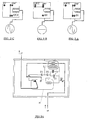
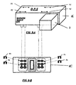
- Figs. 4a - 4c is an external back-up unit 14 used for backing-up OPT receiver 10.
- Figs. 4a and 4b show housing 20 of external back-up unit 14.
- Input socket 21 is for the back-up voltage
- input socket 22 is for the voltage supplied by the local power supply.
- Output socket 23 is connected to a trunk amplifier and OPT via an additional L.P.I. (Not shown).
- Connectors 21', 22' and 23' indicate the manner in which external back-up unit 14 is connected to the network.
- Fig. 4c indicates how the switching works between normal power source 24 and back-up power source 25.
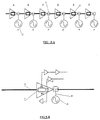
- Fig. 5a shows cable 1 originating in a television station (not shown) connecting trunks A, B, C, D, E and F in cascade to each other.
- Each of said trunk comprises a relay 2.
- All L.P.I units 9 are connected to the Out position by 2 fuses directing the supply voltage into 2 directions (See Fig. 5b.)
- Electric sources A' to F' are connected to the general network via L.P.I. units 9.
- Fig. 5b shows trunk B (by way of example only comprising relay 2 as back-up unit (normal "Out” and back-up "In”).
- Lexes 6 are connected as shown in Fig. 1b.
- Electric source 7 is connected by cable 8 to L.P.I. 9 which is connected to the outside of trunk B.
- Fig. 5c shows the same system as shown in Fig. 5b comprising in addition electric source 8.
- Figs. 5d and 5e show an one way back-up unit of the system shown in Figs. 5a - 5c in “on” and “off” positions. (Normal “out” and backup “in”).
- the system shown in Fig. 6a comprises cable 1 originating in the television station (not shown) connecting Trunks V1 - V6 in cascade to each other.
- Each of said trunks comprises a back-up unit called normal bridger back-up in/out.
- Each local power supply PS1 - PS6 is connected to the corresponding trunk into one of the bridger outputs F1 - F4.
- Power supply 7' is used for back-up only and connected to cable 1 by L.P.I. 9.
- L.P.I. 9 In order to connect back-up voltage to the two directions of L.P.I. 9 there are present 2 fuses inside said L.P.I.
- Fig. 6b shows trunk V2 (by way of example only) comprising switching means (relay) 2.
- Power supply 7 is connected to bridger output F4 (by way of example).
- Power supply 7 is connected to all lexes 5 being connected to outputs F1, F2 and F3 and to trunk amplifier in truck V2.
- the back-up power is connected to cable 1.
- Fig. 6c shows the back-up according to the system shown in Figs. 6a and 6b.
- Power supply 7' is connected to cable 1 between the trunks (as in Fig. 6a).
- Power supply 7 is connected to bridger output F4 located in the corresponding trunk.
- Bridger outputs F1, F2, F3... are connected to lexes 6.
- V1' shows the input voltage socket supplying power to the trunk amplifier only.
- the back-up unit shown in Figs. 7a and 7b is for a Jerrold® trunk.
- Relay 2 is inserted into housing 10.
- Cable 11 is inserted by plug 12 into voltage supply selecting socket 13.
- the back-up unit shown in Figs. 8a and 8b is for a Magnavox® trunk.
- Housing A' of relay 2 is connected directly to fuse socket A" of trunk A (not shown).
- Fuses (F1' - F4') are inserted into housing A', instead of original fuses (F1 - F4). It is possible to use the original bridger fuse sockets (F1 - F4) with different kinds of housing A'.
Landscapes
- Engineering & Computer Science (AREA)
- Multimedia (AREA)
- Signal Processing (AREA)
- Business, Economics & Management (AREA)
- Emergency Management (AREA)
- Power Engineering (AREA)
- Cable Transmission Systems, Equalization Of Radio And Reduction Of Echo (AREA)
- Details Of Television Systems (AREA)
Claims (16)
- Sicherungssystem für die Spannungsversorgung von Hauptleitungsverstärkern und Nebenleitungsverteilverstärkern in einem Fernsehkabelsystem bei Störungen in der elektrischen Versorgung, wobei jeder Hauptleitungsverstärker eine Schalteinrichtung (2) aufweist, dadurch gekennzeichnet, dass die Schalteinrichtung zwischen zwei Wechselspannungsquellen schaltbar ist, wobei eine erste Wechselspannungsquelle eine lokale Spannungsquelle (C') ist und eine zweite Wechselspannungsquelle die elektrische Versorgung (D') für einen benachbarten Hauptleitungsverstärker (D) ist, und die Schalteinrichtung getätigt wird, wenn eine elektrische Störung in der lokalen Spannungsquelle (C') für den Hauptleitungsverstärker (C) auftritt, wodurch die zweite Wechselspannungsquelle (D'), die als Ersatzversorgung arbeitet, als Spannungsquelle für den Hauptleitungsverstärker (C) geschaltet wird.
- System nach Anspruch 1, bei dem die Schalteinrichtung ein AC-Relais ist.
- System nach Anspruch 2, bei dem das Relais bei 48 bis 68 V arbeitet.
- System nach Anspruch 1, bei dem die Schalteinrichtung ein mit einer Diodenbrücke verbundenes DC-Relais ist.
- System nach einem der Ansprüche 1 bis 4, bei dem der Hauptleitungsverstärker [trunk] ein Magnavox® -Verstärker ist und die Schalteinrichtung mit einem Sicherungsanschluss verbunden ist.
- System nach einem der Ansprüche 1 bis 4, bei dem der Hauptleitungsverstärker [trunk] ein Jerrold® -Verstärker ist und die Schalteinrichtung mit einer Steckfassung zum Wählen der Spannungsversorgung verbunden ist.
- System nach einem der Ansprüche 1 bis 6, das mehr als eine Schalteinrichtung umfasst.
- System nach einem der Ansprüche 1 bis 7, bei dem die Spannungsquelle über einen lokalen Leistungseinsatz (4, 4') mit der Schalteinrichtung verbunden ist.
- System nach einem der Ansprüche 1 bis 7, bei dem die Spannungsquelle direkt mit einer der nicht verwendeten Brücken [bridgers] (F4) verbunden ist.
- System nach einem der Ansprüche 1 bis 9, bei dem mehr als eine Spannungsquelle mit dem Hauptleitungsverstärker verbunden ist.
- System nach Anspruch 1, bei dem das Kabelsystem mehrere Hauptleitungsverstärker in Kaskadenanordnung enthält und mit 2 Zwei-Wege-Ersatzeinheiten (5, 5') ausgestattet ist, wobei die Einheiten außerhalb und zwischen zwei oder mehr Hauptleitungsverstärkern der Kaskade platziert sind, wobei jede Einheit über einen lokalen Leistungseinsatz mit einem separaten Hauptleitungsverstärker (E, F) und einer separaten Spannungsquelle (E", F') verbunden ist, wobei die Einheiten in entgegengesetzten Richtungen Leistung zuführen und jede Einheit eine Schaltung zum Einleiten des Schaltvorgangs und eine Schaltung zur Aufrechterhaltung der Ersatzversorgung aufweist.
- System nach Anspruch 11, bei dem die Schaltung zum Einleiten des Schaltvorgangs eine Diode (D2) und ein Relais (16) umfasst und die Schaltung zur Aufrechterhaltung der Ersatzversorgung einen Transformator (T1), Dioden (D2, Z1) und ein Relais (16) umfasst.
- System nach einem der Ansprüche 1 bis 11, bei dem die Ersatzversorgung aus einem vorhergehenden Hauptleitungsverstärker abgeleitet ist.
- System nach einem der Ansprüche 1 bis 11, bei dem die Ersatzversorgung aus einem nachfolgenden Hauptleitungsverstärker abgeleitet ist.
- System nach einem der Ansprüche 1 bis 11, bei dem die Ersatzversorgung aus einer gemeinsamen Stromversorgungsleitung abgeleitet ist.
- System nach Anspruch 12, bei dem das Relais (16) für beide Schaltungen gemeinsam ist.
Applications Claiming Priority (2)
| Application Number | Priority Date | Filing Date | Title |
|---|---|---|---|
| IL11132194 | 1994-10-18 | ||
| IL11132194A IL111321A (en) | 1994-10-18 | 1994-10-18 | Back-up system for the supply of voltage in television cable systems |
Publications (3)
| Publication Number | Publication Date |
|---|---|
| EP0708559A2 EP0708559A2 (de) | 1996-04-24 |
| EP0708559A3 EP0708559A3 (de) | 1997-03-12 |
| EP0708559B1 true EP0708559B1 (de) | 2001-07-04 |
Family
ID=11066660
Family Applications (1)
| Application Number | Title | Priority Date | Filing Date |
|---|---|---|---|
| EP95307383A Expired - Lifetime EP0708559B1 (de) | 1994-10-18 | 1995-10-17 | Sicherungssystem für die Spannungsversorgung in einem Fernsehkabelsystem |
Country Status (5)
| Country | Link |
|---|---|
| EP (1) | EP0708559B1 (de) |
| CA (1) | CA2160747C (de) |
| DE (1) | DE69521583T2 (de) |
| ES (1) | ES2160673T3 (de) |
| IL (1) | IL111321A (de) |
Families Citing this family (1)
| Publication number | Priority date | Publication date | Assignee | Title |
|---|---|---|---|---|
| MX2021001389A (es) * | 2021-02-03 | 2022-08-04 | Secure Power System Llc | Sistema de respaldo de energia para redes de television por cable. |
Family Cites Families (4)
| Publication number | Priority date | Publication date | Assignee | Title |
|---|---|---|---|---|
| DE2310885B2 (de) | 1973-03-05 | 1978-10-26 | Kabel- Und Metallwerke Gutehoffnungshuette Ag, 3000 Hannover | Verfahren zur Gleichstromfernspeisung in einem System zur Übertragung und Verteilung von Hochfrequenz-Energie |
| US4412245A (en) * | 1980-10-01 | 1983-10-25 | Gte Products Corporation | Differential current detector in cable television trunk amplifier station |
| JPH0618353B2 (ja) * | 1985-10-17 | 1994-03-09 | 松下電器産業株式会社 | 1ウエイアドレツサブルシステム |
| US5434610A (en) * | 1992-07-13 | 1995-07-18 | Scientific-Atlanta, Inc. | Methods and apparatus for the reconfiguration of cable television systems |
-
1994
- 1994-10-18 IL IL11132194A patent/IL111321A/xx not_active IP Right Cessation
-
1995
- 1995-10-17 ES ES95307383T patent/ES2160673T3/es not_active Expired - Lifetime
- 1995-10-17 EP EP95307383A patent/EP0708559B1/de not_active Expired - Lifetime
- 1995-10-17 DE DE69521583T patent/DE69521583T2/de not_active Expired - Fee Related
- 1995-10-17 CA CA002160747A patent/CA2160747C/en not_active Expired - Fee Related
Also Published As
| Publication number | Publication date |
|---|---|
| DE69521583T2 (de) | 2002-05-29 |
| IL111321A0 (en) | 1994-12-29 |
| CA2160747A1 (en) | 1996-04-19 |
| DE69521583D1 (de) | 2001-08-09 |
| CA2160747C (en) | 2002-01-01 |
| EP0708559A2 (de) | 1996-04-24 |
| EP0708559A3 (de) | 1997-03-12 |
| IL111321A (en) | 1999-04-11 |
| ES2160673T3 (es) | 2001-11-16 |
Similar Documents
| Publication | Publication Date | Title |
|---|---|---|
| US5747888A (en) | Back up system for the supply of voltage in television cable systems | |
| US4131805A (en) | Line power cord adaptor | |
| US4462656A (en) | Installation system of labeled conductors including plugs and connecting centers | |
| CA2244177A1 (en) | Power distribution unit with individual gfi modules and a line supervisory circuit | |
| US6146149A (en) | Building entrance protector with replaceable fusible link assembly | |
| US5719693A (en) | Power feeding system for an optical transmission system | |
| AU645658B2 (en) | Submarine telecommunications systems | |
| USRE45064E1 (en) | Power distribution bus with protection and alarming | |
| EP0708559B1 (de) | Sicherungssystem für die Spannungsversorgung in einem Fernsehkabelsystem | |
| US6320732B1 (en) | Electrical power distribution control system with dual voltage sources | |
| US5790358A (en) | Feeding pass switching circuit | |
| WO1997026695A3 (de) | Verbindungsanordnung für verbrauchernetze | |
| US20240114645A1 (en) | Modular and scalable power distribution | |
| JPH06103887B2 (ja) | ローカルエリアネットワークのアクセスユニット | |
| US5619494A (en) | Access unit for local area network and concentrator system thereof | |
| US20030120967A1 (en) | Protection switch to support redundant application of converter units | |
| KR960013787A (ko) | 철도차량의 연장급전회로 | |
| CN216056339U (zh) | 一种基于有限电源容量的配电组合系统 | |
| US4176320A (en) | Transmission trunk powering system | |
| US5627491A (en) | Plural stage circuit with automatic adaptation to first and second voltage ranges of a common voltage source | |
| EP1437840B1 (de) | Unterseekabelverzweigungseinheit | |
| JPS639233Y2 (de) | ||
| JPS5879344A (ja) | 海底中継方式 | |
| WO2023141190A1 (en) | Modular and scalable power distribution system | |
| EP0873655A1 (de) | Zwischenkopplungsvorrichtung in einem fernmeldesystem |
Legal Events
| Date | Code | Title | Description |
|---|---|---|---|
| PUAI | Public reference made under article 153(3) epc to a published international application that has entered the european phase |
Free format text: ORIGINAL CODE: 0009012 |
|
| AK | Designated contracting states |
Kind code of ref document: A2 Designated state(s): DE ES FR GB |
|
| PUAL | Search report despatched |
Free format text: ORIGINAL CODE: 0009013 |
|
| AK | Designated contracting states |
Kind code of ref document: A3 Designated state(s): DE ES FR GB |
|
| 17P | Request for examination filed |
Effective date: 19970905 |
|
| 17Q | First examination report despatched |
Effective date: 19990202 |
|
| GRAG | Despatch of communication of intention to grant |
Free format text: ORIGINAL CODE: EPIDOS AGRA |
|
| GRAG | Despatch of communication of intention to grant |
Free format text: ORIGINAL CODE: EPIDOS AGRA |
|
| GRAH | Despatch of communication of intention to grant a patent |
Free format text: ORIGINAL CODE: EPIDOS IGRA |
|
| GRAH | Despatch of communication of intention to grant a patent |
Free format text: ORIGINAL CODE: EPIDOS IGRA |
|
| GRAA | (expected) grant |
Free format text: ORIGINAL CODE: 0009210 |
|
| AK | Designated contracting states |
Kind code of ref document: B1 Designated state(s): DE ES FR GB |
|
| REF | Corresponds to: |
Ref document number: 69521583 Country of ref document: DE Date of ref document: 20010809 |
|
| REG | Reference to a national code |
Ref country code: ES Ref legal event code: FG2A Ref document number: 2160673 Country of ref document: ES Kind code of ref document: T3 |
|
| ET | Fr: translation filed | ||
| REG | Reference to a national code |
Ref country code: GB Ref legal event code: IF02 |
|
| PLBE | No opposition filed within time limit |
Free format text: ORIGINAL CODE: 0009261 |
|
| STAA | Information on the status of an ep patent application or granted ep patent |
Free format text: STATUS: NO OPPOSITION FILED WITHIN TIME LIMIT |
|
| 26N | No opposition filed | ||
| PGFP | Annual fee paid to national office [announced via postgrant information from national office to epo] |
Ref country code: DE Payment date: 20051014 Year of fee payment: 11 |
|
| PGFP | Annual fee paid to national office [announced via postgrant information from national office to epo] |
Ref country code: ES Payment date: 20051129 Year of fee payment: 11 |
|
| PG25 | Lapsed in a contracting state [announced via postgrant information from national office to epo] |
Ref country code: DE Free format text: LAPSE BECAUSE OF NON-PAYMENT OF DUE FEES Effective date: 20070501 |
|
| REG | Reference to a national code |
Ref country code: ES Ref legal event code: FD2A Effective date: 20061018 |
|
| PG25 | Lapsed in a contracting state [announced via postgrant information from national office to epo] |
Ref country code: ES Free format text: LAPSE BECAUSE OF NON-PAYMENT OF DUE FEES Effective date: 20061018 |
|
| PGFP | Annual fee paid to national office [announced via postgrant information from national office to epo] |
Ref country code: FR Payment date: 20100223 Year of fee payment: 15 |
|
| PGFP | Annual fee paid to national office [announced via postgrant information from national office to epo] |
Ref country code: GB Payment date: 20101013 Year of fee payment: 16 |
|
| PG25 | Lapsed in a contracting state [announced via postgrant information from national office to epo] |
Ref country code: FR Free format text: LAPSE BECAUSE OF NON-PAYMENT OF DUE FEES Effective date: 20101102 |
|
| REG | Reference to a national code |
Ref country code: FR Ref legal event code: ST Effective date: 20110630 |
|
| GBPC | Gb: european patent ceased through non-payment of renewal fee |
Effective date: 20111017 |
|
| PG25 | Lapsed in a contracting state [announced via postgrant information from national office to epo] |
Ref country code: GB Free format text: LAPSE BECAUSE OF NON-PAYMENT OF DUE FEES Effective date: 20111017 |