EP0708703B1 - Chaotische schraube für einschneckenextruder - Google Patents
Chaotische schraube für einschneckenextruder Download PDFInfo
- Publication number
- EP0708703B1 EP0708703B1 EP95918205A EP95918205A EP0708703B1 EP 0708703 B1 EP0708703 B1 EP 0708703B1 EP 95918205 A EP95918205 A EP 95918205A EP 95918205 A EP95918205 A EP 95918205A EP 0708703 B1 EP0708703 B1 EP 0708703B1
- Authority
- EP
- European Patent Office
- Prior art keywords
- screw
- mixing
- chaos
- barriers
- barrier
- Prior art date
- Legal status (The legal status is an assumption and is not a legal conclusion. Google has not performed a legal analysis and makes no representation as to the accuracy of the status listed.)
- Expired - Lifetime
Links
- 239000000463 material Substances 0.000 claims abstract description 32
- 230000004888 barrier function Effects 0.000 claims abstract description 30
- 230000010006 flight Effects 0.000 claims abstract description 12
- 238000001125 extrusion Methods 0.000 claims abstract description 10
- 238000007599 discharging Methods 0.000 claims description 2
- 230000000739 chaotic effect Effects 0.000 abstract description 9
- 230000000737 periodic effect Effects 0.000 abstract description 3
- 230000000694 effects Effects 0.000 abstract 1
- 230000004048 modification Effects 0.000 abstract 1
- 238000012986 modification Methods 0.000 abstract 1
- 239000002245 particle Substances 0.000 description 19
- 238000012360 testing method Methods 0.000 description 7
- 239000000155 melt Substances 0.000 description 4
- 238000007796 conventional method Methods 0.000 description 3
- 238000004519 manufacturing process Methods 0.000 description 2
- 230000008018 melting Effects 0.000 description 2
- 238000002844 melting Methods 0.000 description 2
- 238000000034 method Methods 0.000 description 2
- 239000007787 solid Substances 0.000 description 2
- 230000007704 transition Effects 0.000 description 2
- 230000015572 biosynthetic process Effects 0.000 description 1
- 238000006243 chemical reaction Methods 0.000 description 1
- 239000002131 composite material Substances 0.000 description 1
- 230000006835 compression Effects 0.000 description 1
- 238000007906 compression Methods 0.000 description 1
- 238000013461 design Methods 0.000 description 1
- 238000011161 development Methods 0.000 description 1
- 230000018109 developmental process Effects 0.000 description 1
- 239000000975 dye Substances 0.000 description 1
- 239000012530 fluid Substances 0.000 description 1
- 230000006872 improvement Effects 0.000 description 1
- 239000000843 powder Substances 0.000 description 1
- 230000008569 process Effects 0.000 description 1
Images



Classifications
-
- B—PERFORMING OPERATIONS; TRANSPORTING
- B01—PHYSICAL OR CHEMICAL PROCESSES OR APPARATUS IN GENERAL
- B01F—MIXING, e.g. DISSOLVING, EMULSIFYING OR DISPERSING
- B01F27/00—Mixers with rotary stirring devices in fixed receptacles; Kneaders
-
- B—PERFORMING OPERATIONS; TRANSPORTING
- B29—WORKING OF PLASTICS; WORKING OF SUBSTANCES IN A PLASTIC STATE IN GENERAL
- B29C—SHAPING OR JOINING OF PLASTICS; SHAPING OF MATERIAL IN A PLASTIC STATE, NOT OTHERWISE PROVIDED FOR; AFTER-TREATMENT OF THE SHAPED PRODUCTS, e.g. REPAIRING
- B29C48/00—Extrusion moulding, i.e. expressing the moulding material through a die or nozzle which imparts the desired form; Apparatus therefor
- B29C48/25—Component parts, details or accessories; Auxiliary operations
- B29C48/36—Means for plasticising or homogenising the moulding material or forcing it through the nozzle or die
- B29C48/50—Details of extruders
- B29C48/505—Screws
- B29C48/565—Screws having projections other than the thread, e.g. pins
-
- B—PERFORMING OPERATIONS; TRANSPORTING
- B29—WORKING OF PLASTICS; WORKING OF SUBSTANCES IN A PLASTIC STATE IN GENERAL
- B29C—SHAPING OR JOINING OF PLASTICS; SHAPING OF MATERIAL IN A PLASTIC STATE, NOT OTHERWISE PROVIDED FOR; AFTER-TREATMENT OF THE SHAPED PRODUCTS, e.g. REPAIRING
- B29C48/00—Extrusion moulding, i.e. expressing the moulding material through a die or nozzle which imparts the desired form; Apparatus therefor
- B29C48/03—Extrusion moulding, i.e. expressing the moulding material through a die or nozzle which imparts the desired form; Apparatus therefor characterised by the shape of the extruded material at extrusion
- B29C48/04—Particle-shaped
Definitions
- the present invention relates to a screw for a single screw extruder, and particularly to a chaos screw for a single screw extruder, in which the structure is simple, and a superior mixing capability is provided without much modifying the existing structure, thereby realizing improved chaotic mixing characteristics.
- the single screw extruder together with the twin screw extruder is widely used for mixing the materials.
- the single screw extruder is low in its price compared with the twin screw extruder, while the mixing capability of the former lags behind that of the latter.
- the single screw extruder is more widely used than the twin screw extruder for the reason of economy. Therefore, if the insufficiency of the mixing capability which is the disadvantage of the single screw extruder is improved, then there can be developed a single screw extruder which is low in its price and excellent in its mixing capability. Screw extruders of the prior art are disclosed in GB-A-2 137 893 and AT-B-317 523
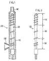
- a conventional single screw extruder 100 includes: a screw 120 within a barrel 110, a hopper 130 formed on a side near one end of the barrel 110, and an extruding die 140 formed at another end of the barrel 140.
- the screw 120 revolves and pushes the pelletized material toward the extruding die 140, thereby discharging the extrusion material. During this process, the pelletized material is melted into a fluid.
- the structure of the screw 120 of the single screw extruder 100 is illustrated in FIG. 2.
- This screw 120 is generally divided into: a delay melting or solid conveying zone 150, a melting or compression or transition zone 160, and a melt conveying or metering zone 170.
- Many studies have been made for the geometric contours of the respective zones, and there are many related patents. Most of the mentioned patents are aimed at improving the geometric contours of the solid conveying zone, the transition zone and the melt conveying zone for reducing the energy loss.
- the screw characteristics refer to a throughput as a function of the pressure gradient within the screw and the revolution speed of the screw.
- the screw characteristics refer to a throughput as a function of the pressure gradient within the screw and the revolution speed of the screw.
- the complicated contour of the conventional screws aggravates the screw characteristics, while the adjustment of the throughput based on the relation between the die and the revolution speed of the screw becomes difficult. Therefore, optimum design of such screws is quite difficult to achieve due to the complicated geometry.
- the present invention is intended to overcome the above described disadvantages of the conventional techniques.
- the chaos screw for a single screw extruder includes: a hopper formed on a side near one end of a barrel; an extruding die formed on another side of the barrel; and a screw installed within the barrel to push an extrusion material from the hopper toward the extruding die to discharge the material.
- the chaos screw further includes: a plurality of screw flights for moving forward the extrusion material; a plurality of barriers provided between said screw flights; the barriers having a periodic structure with barrier existing zones and barrier non-existing zones periodically repeated; and the barriers being formed on the whole melt conveying region in which the screw flights are formed, whereby a chaotic mixing of the extrusion material is realized.
- the barriers are formed in the same shape as that of the screw flights.
- a chaos screw 1 according to the present invention is illustrated in FIG. 4. Before describing the chaos screw 1, the chaos mixing concept which is relevant to the present invention will be described together with the general flow state of the conventional screw.
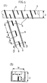
- the velocity distribution is calculated after converting the spiral channels formed in the axial direction of the extruder into planes. Based on this conversion, the trajectories of the material particles can be obtained, and a typical trajectory of the material particle is illustrated in FIGs. 3A and 3B.
- the present inventor will call the closed stream line a shell S.
- the material particles P which exist within the shell SW cannot be transferred to another shell. Further, the material particles P which exist within an arbitrary shell S undergo deformations.
- the degree of mixing through the deformation increases in a linear form in the lengthwise direction of the extruder. This is an evidence to the fact that the mixing within the single screw extruder occurs due to a regular laminar mixing. Thus the fact that the mixing or the deformation linearly increases indicates a limit to the mixing capability of the single screw extruder.
- the chaos screw 1 which is illustrated in FIG. 4 has a chaotic mixing characteristics to improve the mixing capability of the single screw extruder.
- FIG. 5A illustrates the channel of the region A of FIG. 4, while FIG. 5B is a sectional view taken along a line B-B of FIG. 5A.
- a plurality of barriers (or breakers) 9 which are shaped like a screw flight 8 are periodically installed, so that the typical flow in a region without barriers can be periodically deformed in a region having barriers, this being the basic principle of the present invention.
- the structure is such that a portion a having a barrier 9 and a portion b having no barrier are periodically repeated (e.g., (a)(b)-(a)(b)-(a)(b).).
- the form of (a)(b)-(a)(b)-(a)(b).... is not necessarily required. That is, when (a)(b)-(a)(b)-(a)(b)... are repeated, it includes the case that the dimensions of the repeated (a) and (b) are varied.
- the gap c between the screw flight 8 and the barrier 9 which is illustrated in FIG. 5B is in principle larger than zero (0) and smaller than the channel width W.
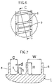
- FIG. 6 illustrates in detail in an enlarged scale the region A of FIG. 4 to show the basic concept of the chaos screw.
- FIG. 7 is a sectional view taken along a line C-C of FIG. 6, and here, c, d, h and H are adjusted to obtain the optimum mixing performance. That is, in FIG. 7, the gap c between the screw flight 8 and the barrier 9 includes all the ranges which are larger than zero and smaller than the channel width. Further, the height h of the barrier 9 includes all the ranges which are larger than zero and smaller than the height H of the screw flight. The gap c and the height h include all the ranges which can be varied within the channel width W and the height H. Further, the thickness d of the barrier 9 is equal to or smaller than the thickness of the screw flight.
- material particles P which have been existing within a certain shell S can be transferred to another shell, and periodic repetition of such transfers leads to a chaotic mixing.
- the structure of the flight 8 is not modified, and therefore, the screw characteristics can be maintained.
- the formation of the barriers 9, they have the same shape as that of the screw flight 8, and therefore, they can be formed by using a numeric controlled (NC) lathe, so that they can be machined simultaneously, thereby making it possible to save the manufacturing cost.
- NC numeric controlled
- a small volume of high molecular material colored with a dye stuff was mixed with a large volume of transparent high molecular material and was put into an extruder, and then an extrusion was carried out. Then a cooled barrel was opened to observe the mixing procedure.
- FIG. 8 The representative result of this test is illustrated in FIG. 8. Meanwhile, the material which was processed along the channel of the chaos screw of the present invention was sliced to test it, and FIG. 9 is a photograph showing the test result. As can be seen in the photographs, the degree of the mixing at the end of the channel is far superior in the chaos screw.
- the particle advancement was realized only within a shell S, so that the particle trajectory T would be maintained in a certain form.
- the advancement direction of the particles P was such that the particles drifted through the whole area of the channel, thereby destroying the certain form. Therefore, by tracing the trajectory of the particles P, it could be confirmed that the mixing performance of the chaos screw of the present invention is far superior than the conventional screw.
Landscapes
- Engineering & Computer Science (AREA)
- Mechanical Engineering (AREA)
- Chemical & Material Sciences (AREA)
- Chemical Kinetics & Catalysis (AREA)
- Extrusion Moulding Of Plastics Or The Like (AREA)
- Processing And Handling Of Plastics And Other Materials For Molding In General (AREA)
Claims (2)
- Schnecke für eine Einzelschnecken-Strangpresse zum Mischen von Extrudiermaterialien in der Einzelschnecken-Strangpresse und zum Abgeben dieser Materialien aus der Einzelschnecken-Strangpresse, enthaltend: mehrere Schraubengänge (8) zum Vorwärtsbewegen des Extrudiermaterials und mehrere Sperrelemente (9), die zwischen den Schraubengängen (8) über den gesamten Schmelzförderbereich (170) vorgesehen sind, in dem die Schraubengänge (8) vorhanden sind, wobei die Sperrelemente (9) eine Höhe (h) aufweisen, die kleiner als die Höhe (H) der Schraubengänge (8) ist,dadurch gekennzeichnet, daß die Sperrelemente (9) in Form einer sich periodisch wiederholenden Struktur (a)(b)-(a)(b)-(a)(b) ... vorgesehen sind, die abwechselnd aus Zonen (a) mit Sperrelementen und Zonen (b) ohne Sperrelemente besteht, unddaß die Lücke (c) zwischen einem Schraubengang (8) und einem Sperrelement (9) über den gesamten Bereich des Schmelzförderbereiches (170) konstant ist, in dem die Schraubengänge (8) vorhanden sind.
- Schnecke nach Anspruch 1,
bei der das Sperrelement (9) eine Dicke (d) aufweist, die größer als Null (0) und kleiner als die Dicke des Schraubenganges (8) ist.
Applications Claiming Priority (5)
| Application Number | Priority Date | Filing Date | Title |
|---|---|---|---|
| KR9410204 | 1994-05-10 | ||
| KR19940010204 | 1994-05-10 | ||
| KR9511276 | 1995-05-09 | ||
| KR1019950011276A KR0140270B1 (ko) | 1994-05-10 | 1995-05-09 | 단축압출기용 카오스 스크류(Chaos Screw) |
| PCT/KR1995/000053 WO1995030530A1 (en) | 1994-05-10 | 1995-05-10 | Chaos screw for single screw extruder |
Publications (2)
| Publication Number | Publication Date |
|---|---|
| EP0708703A1 EP0708703A1 (de) | 1996-05-01 |
| EP0708703B1 true EP0708703B1 (de) | 1999-09-22 |
Family
ID=26630354
Family Applications (1)
| Application Number | Title | Priority Date | Filing Date |
|---|---|---|---|
| EP95918205A Expired - Lifetime EP0708703B1 (de) | 1994-05-10 | 1995-05-10 | Chaotische schraube für einschneckenextruder |
Country Status (6)
| Country | Link |
|---|---|
| EP (1) | EP0708703B1 (de) |
| JP (1) | JPH08511218A (de) |
| KR (1) | KR0140270B1 (de) |
| AT (1) | ATE184832T1 (de) |
| DE (1) | DE69512342T2 (de) |
| WO (1) | WO1995030530A1 (de) |
Families Citing this family (3)
| Publication number | Priority date | Publication date | Assignee | Title |
|---|---|---|---|---|
| KR20030012725A (ko) * | 2001-08-04 | 2003-02-12 | 학교법인 포항공과대학교 | 나선 유동을 이용한 카오스 혼합용 마이크로 채널 및 그제조 방법 |
| KR20040009106A (ko) * | 2002-07-22 | 2004-01-31 | 학교법인 포항공과대학교 | 배리어가 포함된 전자력 추진 마이크로 믹서(mhdbem) 및 그 제조방법 |
| CN102615807A (zh) * | 2012-03-22 | 2012-08-01 | 上海罗洋新材料科技有限公司 | 一种密封型双螺杆 |
Family Cites Families (4)
| Publication number | Priority date | Publication date | Assignee | Title |
|---|---|---|---|---|
| DE2032197A1 (de) * | 1970-06-30 | 1972-01-05 | Uniroyal Ag | Verfahren und Vorrichtung zur Verarbeitung von hochviskosen Werkstoffen, insbesondere Kautschuk-Mischungen, in Einschnecken-Ex trudern |
| GB1591730A (en) * | 1977-12-08 | 1981-06-24 | Iddon Bros Ltd | Screws for extruding machines |
| GB2137893A (en) * | 1983-04-13 | 1984-10-17 | Nat Res Dev | Improvements in or relating to conveying screws |
| JPS61241116A (ja) * | 1985-04-18 | 1986-10-27 | Mitsubishi Heavy Ind Ltd | スクリユ |
-
1995
- 1995-05-09 KR KR1019950011276A patent/KR0140270B1/ko not_active Expired - Fee Related
- 1995-05-10 DE DE69512342T patent/DE69512342T2/de not_active Expired - Fee Related
- 1995-05-10 WO PCT/KR1995/000053 patent/WO1995030530A1/en not_active Ceased
- 1995-05-10 JP JP7528851A patent/JPH08511218A/ja active Pending
- 1995-05-10 AT AT95918205T patent/ATE184832T1/de not_active IP Right Cessation
- 1995-05-10 EP EP95918205A patent/EP0708703B1/de not_active Expired - Lifetime
Also Published As
| Publication number | Publication date |
|---|---|
| DE69512342D1 (de) | 1999-10-28 |
| KR950031198A (ko) | 1995-12-18 |
| EP0708703A1 (de) | 1996-05-01 |
| ATE184832T1 (de) | 1999-10-15 |
| JPH08511218A (ja) | 1996-11-26 |
| KR0140270B1 (ko) | 1998-06-01 |
| WO1995030530A1 (en) | 1995-11-16 |
| DE69512342T2 (de) | 2000-04-20 |
Similar Documents
| Publication | Publication Date | Title |
|---|---|---|
| EP0002131B1 (de) | Verbesserter selbstreinigender Extruder | |
| US4298328A (en) | Extrusion apparatus for preventing the distortion of peripheral cells in extruded honeycomb structures | |
| KR100186826B1 (ko) | 고성능 압출기 | |
| US6682213B2 (en) | Twin-screw continuous kneading apparatus and kneading method using the same | |
| US3923438A (en) | Apparatus for making variegated soap base | |
| US5308568A (en) | Extrusion die and method | |
| US4457685A (en) | Extrusion die for shaped extrudate | |
| US5066444A (en) | Process and apparatus for reducing color contamination in the process recycle of zippered thermoplastic bags | |
| EP0776743A1 (de) | Strangpressmundstück für Wabenstruktur und Verfahren zu seiner Herstellung | |
| US4364888A (en) | Method and apparatus for extruding a honeycomb structure | |
| EP0275162B1 (de) | Mundstück zum Extrudieren einer Wabenstruktur | |
| EP0529333B1 (de) | Kontinuierlicher Knetapparat | |
| EP0708703B1 (de) | Chaotische schraube für einschneckenextruder | |
| EP0744271B1 (de) | Filter für Harzextruder | |
| EP0357004B1 (de) | Verfahren und Vorrichtung zur Bearbeitung von potentiell explosiven und empfindlichen Materialien zum Formen von länglichen perforierten extrudierten Strängen | |
| US3770357A (en) | Extrusion die | |
| US6514062B2 (en) | Die for use in an underwater granulating apparatus | |
| WO2006026301A2 (en) | Open cavity extrusion dies | |
| Rauwendaal | Extruder screws with barrier sections | |
| JPH0376721A (ja) | 熱可塑性樹脂球状粒子の製造法 | |
| JPS59202835A (ja) | 高混練スクリユ | |
| US6352425B1 (en) | Rotating disk extruder | |
| GB2700908A (en) | Extrusion machine and method of extrusion | |
| CA2057614C (en) | High-performance extruder | |
| JPS61212268A (ja) | 押出機用ダイ |
Legal Events
| Date | Code | Title | Description |
|---|---|---|---|
| PUAI | Public reference made under article 153(3) epc to a published international application that has entered the european phase |
Free format text: ORIGINAL CODE: 0009012 |
|
| 17P | Request for examination filed |
Effective date: 19960103 |
|
| AK | Designated contracting states |
Kind code of ref document: A1 Designated state(s): AT CH DE FR GB IT LI |
|
| 17Q | First examination report despatched |
Effective date: 19971202 |
|
| GRAG | Despatch of communication of intention to grant |
Free format text: ORIGINAL CODE: EPIDOS AGRA |
|
| GRAG | Despatch of communication of intention to grant |
Free format text: ORIGINAL CODE: EPIDOS AGRA |
|
| GRAH | Despatch of communication of intention to grant a patent |
Free format text: ORIGINAL CODE: EPIDOS IGRA |
|
| GRAH | Despatch of communication of intention to grant a patent |
Free format text: ORIGINAL CODE: EPIDOS IGRA |
|
| GRAA | (expected) grant |
Free format text: ORIGINAL CODE: 0009210 |
|
| AK | Designated contracting states |
Kind code of ref document: B1 Designated state(s): AT CH DE FR GB IT LI |
|
| REF | Corresponds to: |
Ref document number: 184832 Country of ref document: AT Date of ref document: 19991015 Kind code of ref document: T |
|
| REG | Reference to a national code |
Ref country code: CH Ref legal event code: EP |
|
| REF | Corresponds to: |
Ref document number: 69512342 Country of ref document: DE Date of ref document: 19991028 |
|
| ET | Fr: translation filed | ||
| ITF | It: translation for a ep patent filed | ||
| PLBE | No opposition filed within time limit |
Free format text: ORIGINAL CODE: 0009261 |
|
| STAA | Information on the status of an ep patent application or granted ep patent |
Free format text: STATUS: NO OPPOSITION FILED WITHIN TIME LIMIT |
|
| 26N | No opposition filed | ||
| REG | Reference to a national code |
Ref country code: GB Ref legal event code: IF02 |
|
| PGFP | Annual fee paid to national office [announced via postgrant information from national office to epo] |
Ref country code: CH Payment date: 20040427 Year of fee payment: 10 |
|
| PGFP | Annual fee paid to national office [announced via postgrant information from national office to epo] |
Ref country code: GB Payment date: 20040511 Year of fee payment: 10 |
|
| PGFP | Annual fee paid to national office [announced via postgrant information from national office to epo] |
Ref country code: AT Payment date: 20040525 Year of fee payment: 10 |
|
| PGFP | Annual fee paid to national office [announced via postgrant information from national office to epo] |
Ref country code: FR Payment date: 20040527 Year of fee payment: 10 |
|
| PGFP | Annual fee paid to national office [announced via postgrant information from national office to epo] |
Ref country code: DE Payment date: 20040603 Year of fee payment: 10 |
|
| PG25 | Lapsed in a contracting state [announced via postgrant information from national office to epo] |
Ref country code: IT Free format text: LAPSE BECAUSE OF NON-PAYMENT OF DUE FEES Effective date: 20050510 Ref country code: GB Free format text: LAPSE BECAUSE OF NON-PAYMENT OF DUE FEES Effective date: 20050510 Ref country code: AT Free format text: LAPSE BECAUSE OF NON-PAYMENT OF DUE FEES Effective date: 20050510 |
|
| PG25 | Lapsed in a contracting state [announced via postgrant information from national office to epo] |
Ref country code: LI Free format text: LAPSE BECAUSE OF NON-PAYMENT OF DUE FEES Effective date: 20050531 Ref country code: CH Free format text: LAPSE BECAUSE OF NON-PAYMENT OF DUE FEES Effective date: 20050531 |
|
| PG25 | Lapsed in a contracting state [announced via postgrant information from national office to epo] |
Ref country code: DE Free format text: LAPSE BECAUSE OF NON-PAYMENT OF DUE FEES Effective date: 20051201 |
|
| REG | Reference to a national code |
Ref country code: CH Ref legal event code: PL |
|
| GBPC | Gb: european patent ceased through non-payment of renewal fee |
Effective date: 20050510 |
|
| PG25 | Lapsed in a contracting state [announced via postgrant information from national office to epo] |
Ref country code: FR Free format text: LAPSE BECAUSE OF NON-PAYMENT OF DUE FEES Effective date: 20060131 |
|
| REG | Reference to a national code |
Ref country code: FR Ref legal event code: ST Effective date: 20060131 |