EP0708827B1 - Reinigungsmethode und entsprechende vorrichtung - Google Patents
Reinigungsmethode und entsprechende vorrichtung Download PDFInfo
- Publication number
- EP0708827B1 EP0708827B1 EP94919795A EP94919795A EP0708827B1 EP 0708827 B1 EP0708827 B1 EP 0708827B1 EP 94919795 A EP94919795 A EP 94919795A EP 94919795 A EP94919795 A EP 94919795A EP 0708827 B1 EP0708827 B1 EP 0708827B1
- Authority
- EP
- European Patent Office
- Prior art keywords
- chamber
- filter
- matrix
- cells
- solid phase
- Prior art date
- Legal status (The legal status is an assumption and is not a legal conclusion. Google has not performed a legal analysis and makes no representation as to the accuracy of the status listed.)
- Expired - Lifetime
Links
- 238000000034 method Methods 0.000 title claims abstract description 49
- 238000000746 purification Methods 0.000 title claims abstract description 19
- 239000011159 matrix material Substances 0.000 claims abstract description 75
- 150000001875 compounds Chemical class 0.000 claims abstract description 36
- 108020004707 nucleic acids Proteins 0.000 claims abstract description 35
- 102000039446 nucleic acids Human genes 0.000 claims abstract description 35
- 150000007523 nucleic acids Chemical class 0.000 claims abstract description 35
- 239000007790 solid phase Substances 0.000 claims abstract description 29
- 239000006285 cell suspension Substances 0.000 claims abstract description 26
- 239000006166 lysate Substances 0.000 claims abstract description 15
- 239000013592 cell lysate Substances 0.000 claims abstract description 9
- 230000002934 lysing effect Effects 0.000 claims abstract description 4
- 210000004027 cell Anatomy 0.000 claims description 79
- 239000007788 liquid Substances 0.000 claims description 40
- 239000000706 filtrate Substances 0.000 claims description 18
- 230000004888 barrier function Effects 0.000 claims description 13
- 239000000872 buffer Substances 0.000 claims description 12
- 239000000463 material Substances 0.000 claims description 12
- 239000013612 plasmid Substances 0.000 claims description 12
- 230000000717 retained effect Effects 0.000 claims description 11
- 239000000725 suspension Substances 0.000 claims description 11
- 238000011144 upstream manufacturing Methods 0.000 claims description 8
- 239000012530 fluid Substances 0.000 claims description 7
- 239000011148 porous material Substances 0.000 claims description 6
- 230000027455 binding Effects 0.000 claims description 5
- 239000000356 contaminant Substances 0.000 claims description 5
- 238000005406 washing Methods 0.000 claims description 5
- 210000004369 blood Anatomy 0.000 claims description 4
- 239000008280 blood Substances 0.000 claims description 4
- 210000000601 blood cell Anatomy 0.000 claims description 4
- 238000010828 elution Methods 0.000 claims description 3
- 238000005342 ion exchange Methods 0.000 claims description 3
- 238000005349 anion exchange Methods 0.000 claims 1
- 238000001035 drying Methods 0.000 claims 1
- 238000005119 centrifugation Methods 0.000 abstract description 6
- 239000003153 chemical reaction reagent Substances 0.000 description 47
- 239000000243 solution Substances 0.000 description 21
- 238000007792 addition Methods 0.000 description 19
- 239000002699 waste material Substances 0.000 description 15
- 230000001580 bacterial effect Effects 0.000 description 14
- 230000009089 cytolysis Effects 0.000 description 11
- LFQSCWFLJHTTHZ-UHFFFAOYSA-N Ethanol Chemical compound CCO LFQSCWFLJHTTHZ-UHFFFAOYSA-N 0.000 description 10
- 239000002245 particle Substances 0.000 description 9
- 102000004169 proteins and genes Human genes 0.000 description 9
- 241000894006 Bacteria Species 0.000 description 8
- FAPWRFPIFSIZLT-UHFFFAOYSA-M Sodium chloride Chemical compound [Na+].[Cl-] FAPWRFPIFSIZLT-UHFFFAOYSA-M 0.000 description 8
- VYPSYNLAJGMNEJ-UHFFFAOYSA-N Silicium dioxide Chemical compound O=[Si]=O VYPSYNLAJGMNEJ-UHFFFAOYSA-N 0.000 description 7
- 230000008569 process Effects 0.000 description 7
- 108090000623 proteins and genes Proteins 0.000 description 7
- 230000004568 DNA-binding Effects 0.000 description 6
- KCXVZYZYPLLWCC-UHFFFAOYSA-N EDTA Chemical compound OC(=O)CN(CC(O)=O)CCN(CC(O)=O)CC(O)=O KCXVZYZYPLLWCC-UHFFFAOYSA-N 0.000 description 6
- 241001524679 Escherichia virus M13 Species 0.000 description 6
- 108050007496 Shikimate kinase 2 Proteins 0.000 description 6
- HEMHJVSKTPXQMS-UHFFFAOYSA-M Sodium hydroxide Chemical compound [OH-].[Na+] HEMHJVSKTPXQMS-UHFFFAOYSA-M 0.000 description 6
- 239000011230 binding agent Substances 0.000 description 6
- 229960001484 edetic acid Drugs 0.000 description 6
- 239000012139 lysis buffer Substances 0.000 description 6
- 239000012149 elution buffer Substances 0.000 description 5
- 230000003993 interaction Effects 0.000 description 5
- 230000007246 mechanism Effects 0.000 description 5
- 238000006386 neutralization reaction Methods 0.000 description 5
- 238000002360 preparation method Methods 0.000 description 5
- 239000011347 resin Substances 0.000 description 5
- 229920005989 resin Polymers 0.000 description 5
- 239000011534 wash buffer Substances 0.000 description 5
- XLYOFNOQVPJJNP-UHFFFAOYSA-N water Substances O XLYOFNOQVPJJNP-UHFFFAOYSA-N 0.000 description 5
- QKNYBSVHEMOAJP-UHFFFAOYSA-N 2-amino-2-(hydroxymethyl)propane-1,3-diol;hydron;chloride Chemical compound Cl.OCC(N)(CO)CO QKNYBSVHEMOAJP-UHFFFAOYSA-N 0.000 description 4
- 239000002609 medium Substances 0.000 description 4
- 238000002156 mixing Methods 0.000 description 4
- 239000000203 mixture Substances 0.000 description 4
- SCVFZCLFOSHCOH-UHFFFAOYSA-M potassium acetate Chemical compound [K+].CC([O-])=O SCVFZCLFOSHCOH-UHFFFAOYSA-M 0.000 description 4
- 150000003839 salts Chemical class 0.000 description 4
- 239000011780 sodium chloride Substances 0.000 description 4
- QTBSBXVTEAMEQO-UHFFFAOYSA-N Acetic acid Chemical compound CC(O)=O QTBSBXVTEAMEQO-UHFFFAOYSA-N 0.000 description 3
- 239000005909 Kieselgur Substances 0.000 description 3
- DBMJMQXJHONAFJ-UHFFFAOYSA-M Sodium laurylsulphate Chemical compound [Na+].CCCCCCCCCCCCOS([O-])(=O)=O DBMJMQXJHONAFJ-UHFFFAOYSA-M 0.000 description 3
- 210000003743 erythrocyte Anatomy 0.000 description 3
- 238000001914 filtration Methods 0.000 description 3
- 239000010808 liquid waste Substances 0.000 description 3
- 229920001343 polytetrafluoroethylene Polymers 0.000 description 3
- 239000004810 polytetrafluoroethylene Substances 0.000 description 3
- 238000000108 ultra-filtration Methods 0.000 description 3
- 238000013022 venting Methods 0.000 description 3
- NWUYHJFMYQTDRP-UHFFFAOYSA-N 1,2-bis(ethenyl)benzene;1-ethenyl-2-ethylbenzene;styrene Chemical compound C=CC1=CC=CC=C1.CCC1=CC=CC=C1C=C.C=CC1=CC=CC=C1C=C NWUYHJFMYQTDRP-UHFFFAOYSA-N 0.000 description 2
- -1 DNA Chemical class 0.000 description 2
- 241000588724 Escherichia coli Species 0.000 description 2
- 108091005461 Nucleic proteins Proteins 0.000 description 2
- 239000002202 Polyethylene glycol Substances 0.000 description 2
- 239000005388 borosilicate glass Substances 0.000 description 2
- 239000003729 cation exchange resin Substances 0.000 description 2
- 150000001768 cations Chemical class 0.000 description 2
- 238000004113 cell culture Methods 0.000 description 2
- 229920002301 cellulose acetate Polymers 0.000 description 2
- 230000000694 effects Effects 0.000 description 2
- 230000002209 hydrophobic effect Effects 0.000 description 2
- 239000012535 impurity Substances 0.000 description 2
- 239000007791 liquid phase Substances 0.000 description 2
- 239000003550 marker Substances 0.000 description 2
- 238000001821 nucleic acid purification Methods 0.000 description 2
- 238000005192 partition Methods 0.000 description 2
- 229920001223 polyethylene glycol Polymers 0.000 description 2
- 235000011056 potassium acetate Nutrition 0.000 description 2
- 239000000047 product Substances 0.000 description 2
- 239000012521 purified sample Substances 0.000 description 2
- 238000000926 separation method Methods 0.000 description 2
- 239000000377 silicon dioxide Substances 0.000 description 2
- 235000019333 sodium laurylsulphate Nutrition 0.000 description 2
- BAZAXWOYCMUHIX-UHFFFAOYSA-M sodium perchlorate Chemical compound [Na+].[O-]Cl(=O)(=O)=O BAZAXWOYCMUHIX-UHFFFAOYSA-M 0.000 description 2
- 229910001488 sodium perchlorate Inorganic materials 0.000 description 2
- 239000000126 substance Substances 0.000 description 2
- 239000004094 surface-active agent Substances 0.000 description 2
- 238000012546 transfer Methods 0.000 description 2
- 102000016911 Deoxyribonucleases Human genes 0.000 description 1
- 108010053770 Deoxyribonucleases Proteins 0.000 description 1
- 101100436551 Drosophila melanogaster nrv1 gene Proteins 0.000 description 1
- 101100493048 Drosophila melanogaster nrv2 gene Proteins 0.000 description 1
- 108010067770 Endopeptidase K Proteins 0.000 description 1
- 241001646716 Escherichia coli K-12 Species 0.000 description 1
- 241000701959 Escherichia virus Lambda Species 0.000 description 1
- 108020002230 Pancreatic Ribonuclease Proteins 0.000 description 1
- 102000005891 Pancreatic ribonuclease Human genes 0.000 description 1
- 108091005804 Peptidases Proteins 0.000 description 1
- 102000035195 Peptidases Human genes 0.000 description 1
- 239000004365 Protease Substances 0.000 description 1
- 102000007056 Recombinant Fusion Proteins Human genes 0.000 description 1
- 108010008281 Recombinant Fusion Proteins Proteins 0.000 description 1
- 102000006382 Ribonucleases Human genes 0.000 description 1
- 108010083644 Ribonucleases Proteins 0.000 description 1
- 239000012506 Sephacryl® Substances 0.000 description 1
- 229960000583 acetic acid Drugs 0.000 description 1
- 239000002253 acid Substances 0.000 description 1
- 230000009471 action Effects 0.000 description 1
- 238000000246 agarose gel electrophoresis Methods 0.000 description 1
- 230000001476 alcoholic effect Effects 0.000 description 1
- 239000003146 anticoagulant agent Substances 0.000 description 1
- 229940127219 anticoagulant drug Drugs 0.000 description 1
- 239000012298 atmosphere Substances 0.000 description 1
- 230000008901 benefit Effects 0.000 description 1
- 238000005842 biochemical reaction Methods 0.000 description 1
- 230000005587 bubbling Effects 0.000 description 1
- 239000007853 buffer solution Substances 0.000 description 1
- 229940023913 cation exchange resins Drugs 0.000 description 1
- 239000008004 cell lysis buffer Substances 0.000 description 1
- 230000003196 chaotropic effect Effects 0.000 description 1
- 239000002738 chelating agent Substances 0.000 description 1
- 239000003795 chemical substances by application Substances 0.000 description 1
- 238000011437 continuous method Methods 0.000 description 1
- 230000001276 controlling effect Effects 0.000 description 1
- 238000007796 conventional method Methods 0.000 description 1
- 238000010586 diagram Methods 0.000 description 1
- 238000009585 enzyme analysis Methods 0.000 description 1
- 238000000605 extraction Methods 0.000 description 1
- 238000005194 fractionation Methods 0.000 description 1
- 239000012362 glacial acetic acid Substances 0.000 description 1
- 239000001963 growth medium Substances 0.000 description 1
- 229960000789 guanidine hydrochloride Drugs 0.000 description 1
- PJJJBBJSCAKJQF-UHFFFAOYSA-N guanidinium chloride Chemical compound [Cl-].NC(N)=[NH2+] PJJJBBJSCAKJQF-UHFFFAOYSA-N 0.000 description 1
- 210000003000 inclusion body Anatomy 0.000 description 1
- 239000003456 ion exchange resin Substances 0.000 description 1
- 229920003303 ion-exchange polymer Polymers 0.000 description 1
- 150000002500 ions Chemical class 0.000 description 1
- 210000000265 leukocyte Anatomy 0.000 description 1
- 229920002521 macromolecule Polymers 0.000 description 1
- 229910021645 metal ion Inorganic materials 0.000 description 1
- 230000003472 neutralizing effect Effects 0.000 description 1
- 210000003463 organelle Anatomy 0.000 description 1
- 238000001556 precipitation Methods 0.000 description 1
- 230000001105 regulatory effect Effects 0.000 description 1
- 108091008146 restriction endonucleases Proteins 0.000 description 1
- 239000012266 salt solution Substances 0.000 description 1
- 239000000523 sample Substances 0.000 description 1
- 238000005070 sampling Methods 0.000 description 1
- 238000012216 screening Methods 0.000 description 1
- 239000002002 slurry Substances 0.000 description 1
- 239000007787 solid Substances 0.000 description 1
- 239000007858 starting material Substances 0.000 description 1
- 239000011800 void material Substances 0.000 description 1
Images
Classifications
-
- C—CHEMISTRY; METALLURGY
- C12—BIOCHEMISTRY; BEER; SPIRITS; WINE; VINEGAR; MICROBIOLOGY; ENZYMOLOGY; MUTATION OR GENETIC ENGINEERING
- C12N—MICROORGANISMS OR ENZYMES; COMPOSITIONS THEREOF; PROPAGATING, PRESERVING, OR MAINTAINING MICROORGANISMS; MUTATION OR GENETIC ENGINEERING; CULTURE MEDIA
- C12N15/00—Mutation or genetic engineering; DNA or RNA concerning genetic engineering, vectors, e.g. plasmids, or their isolation, preparation or purification; Use of hosts therefor
- C12N15/09—Recombinant DNA-technology
- C12N15/10—Processes for the isolation, preparation or purification of DNA or RNA
- C12N15/1003—Extracting or separating nucleic acids from biological samples, e.g. pure separation or isolation methods; Conditions, buffers or apparatuses therefor
- C12N15/1017—Extracting or separating nucleic acids from biological samples, e.g. pure separation or isolation methods; Conditions, buffers or apparatuses therefor by filtration, e.g. using filters, frits, membranes
-
- B—PERFORMING OPERATIONS; TRANSPORTING
- B01—PHYSICAL OR CHEMICAL PROCESSES OR APPARATUS IN GENERAL
- B01J—CHEMICAL OR PHYSICAL PROCESSES, e.g. CATALYSIS OR COLLOID CHEMISTRY; THEIR RELEVANT APPARATUS
- B01J19/00—Chemical, physical or physico-chemical processes in general; Their relevant apparatus
- B01J19/0046—Sequential or parallel reactions, e.g. for the synthesis of polypeptides or polynucleotides; Apparatus and devices for combinatorial chemistry or for making molecular arrays
-
- C—CHEMISTRY; METALLURGY
- C07—ORGANIC CHEMISTRY
- C07K—PEPTIDES
- C07K1/00—General methods for the preparation of peptides, i.e. processes for the organic chemical preparation of peptides or proteins of any length
- C07K1/14—Extraction; Separation; Purification
- C07K1/16—Extraction; Separation; Purification by chromatography
- C07K1/18—Ion-exchange chromatography
-
- C—CHEMISTRY; METALLURGY
- C12—BIOCHEMISTRY; BEER; SPIRITS; WINE; VINEGAR; MICROBIOLOGY; ENZYMOLOGY; MUTATION OR GENETIC ENGINEERING
- C12M—APPARATUS FOR ENZYMOLOGY OR MICROBIOLOGY; APPARATUS FOR CULTURING MICROORGANISMS FOR PRODUCING BIOMASS, FOR GROWING CELLS OR FOR OBTAINING FERMENTATION OR METABOLIC PRODUCTS, i.e. BIOREACTORS OR FERMENTERS
- C12M47/00—Means for after-treatment of the produced biomass or of the fermentation or metabolic products, e.g. storage of biomass
- C12M47/12—Purification
-
- B—PERFORMING OPERATIONS; TRANSPORTING
- B01—PHYSICAL OR CHEMICAL PROCESSES OR APPARATUS IN GENERAL
- B01J—CHEMICAL OR PHYSICAL PROCESSES, e.g. CATALYSIS OR COLLOID CHEMISTRY; THEIR RELEVANT APPARATUS
- B01J2219/00—Chemical, physical or physico-chemical processes in general; Their relevant apparatus
- B01J2219/00274—Sequential or parallel reactions; Apparatus and devices for combinatorial chemistry or for making arrays; Chemical library technology
- B01J2219/00277—Apparatus
- B01J2219/00279—Features relating to reactor vessels
- B01J2219/00281—Individual reactor vessels
- B01J2219/00283—Reactor vessels with top opening
-
- B—PERFORMING OPERATIONS; TRANSPORTING
- B01—PHYSICAL OR CHEMICAL PROCESSES OR APPARATUS IN GENERAL
- B01J—CHEMICAL OR PHYSICAL PROCESSES, e.g. CATALYSIS OR COLLOID CHEMISTRY; THEIR RELEVANT APPARATUS
- B01J2219/00—Chemical, physical or physico-chemical processes in general; Their relevant apparatus
- B01J2219/00274—Sequential or parallel reactions; Apparatus and devices for combinatorial chemistry or for making arrays; Chemical library technology
- B01J2219/00277—Apparatus
- B01J2219/00279—Features relating to reactor vessels
- B01J2219/00281—Individual reactor vessels
- B01J2219/00286—Reactor vessels with top and bottom openings
- B01J2219/00288—Reactor vessels with top and bottom openings in the shape of syringes
-
- B—PERFORMING OPERATIONS; TRANSPORTING
- B01—PHYSICAL OR CHEMICAL PROCESSES OR APPARATUS IN GENERAL
- B01J—CHEMICAL OR PHYSICAL PROCESSES, e.g. CATALYSIS OR COLLOID CHEMISTRY; THEIR RELEVANT APPARATUS
- B01J2219/00—Chemical, physical or physico-chemical processes in general; Their relevant apparatus
- B01J2219/00274—Sequential or parallel reactions; Apparatus and devices for combinatorial chemistry or for making arrays; Chemical library technology
- B01J2219/00277—Apparatus
- B01J2219/00279—Features relating to reactor vessels
- B01J2219/00306—Reactor vessels in a multiple arrangement
-
- B—PERFORMING OPERATIONS; TRANSPORTING
- B01—PHYSICAL OR CHEMICAL PROCESSES OR APPARATUS IN GENERAL
- B01J—CHEMICAL OR PHYSICAL PROCESSES, e.g. CATALYSIS OR COLLOID CHEMISTRY; THEIR RELEVANT APPARATUS
- B01J2219/00—Chemical, physical or physico-chemical processes in general; Their relevant apparatus
- B01J2219/00274—Sequential or parallel reactions; Apparatus and devices for combinatorial chemistry or for making arrays; Chemical library technology
- B01J2219/00277—Apparatus
- B01J2219/00351—Means for dispensing and evacuation of reagents
- B01J2219/00423—Means for dispensing and evacuation of reagents using filtration, e.g. through porous frits
-
- B—PERFORMING OPERATIONS; TRANSPORTING
- B01—PHYSICAL OR CHEMICAL PROCESSES OR APPARATUS IN GENERAL
- B01J—CHEMICAL OR PHYSICAL PROCESSES, e.g. CATALYSIS OR COLLOID CHEMISTRY; THEIR RELEVANT APPARATUS
- B01J2219/00—Chemical, physical or physico-chemical processes in general; Their relevant apparatus
- B01J2219/00274—Sequential or parallel reactions; Apparatus and devices for combinatorial chemistry or for making arrays; Chemical library technology
- B01J2219/00718—Type of compounds synthesised
- B01J2219/0072—Organic compounds
- B01J2219/00722—Nucleotides
-
- B—PERFORMING OPERATIONS; TRANSPORTING
- B01—PHYSICAL OR CHEMICAL PROCESSES OR APPARATUS IN GENERAL
- B01J—CHEMICAL OR PHYSICAL PROCESSES, e.g. CATALYSIS OR COLLOID CHEMISTRY; THEIR RELEVANT APPARATUS
- B01J2219/00—Chemical, physical or physico-chemical processes in general; Their relevant apparatus
- B01J2219/00274—Sequential or parallel reactions; Apparatus and devices for combinatorial chemistry or for making arrays; Chemical library technology
- B01J2219/00718—Type of compounds synthesised
- B01J2219/0072—Organic compounds
- B01J2219/00725—Peptides
-
- C—CHEMISTRY; METALLURGY
- C12—BIOCHEMISTRY; BEER; SPIRITS; WINE; VINEGAR; MICROBIOLOGY; ENZYMOLOGY; MUTATION OR GENETIC ENGINEERING
- C12M—APPARATUS FOR ENZYMOLOGY OR MICROBIOLOGY; APPARATUS FOR CULTURING MICROORGANISMS FOR PRODUCING BIOMASS, FOR GROWING CELLS OR FOR OBTAINING FERMENTATION OR METABOLIC PRODUCTS, i.e. BIOREACTORS OR FERMENTERS
- C12M47/00—Means for after-treatment of the produced biomass or of the fermentation or metabolic products, e.g. storage of biomass
- C12M47/06—Hydrolysis; Cell lysis; Extraction of intracellular or cell wall material
-
- C—CHEMISTRY; METALLURGY
- C40—COMBINATORIAL TECHNOLOGY
- C40B—COMBINATORIAL CHEMISTRY; LIBRARIES, e.g. CHEMICAL LIBRARIES
- C40B40/00—Libraries per se, e.g. arrays, mixtures
- C40B40/04—Libraries containing only organic compounds
- C40B40/06—Libraries containing nucleotides or polynucleotides, or derivatives thereof
-
- C—CHEMISTRY; METALLURGY
- C40—COMBINATORIAL TECHNOLOGY
- C40B—COMBINATORIAL CHEMISTRY; LIBRARIES, e.g. CHEMICAL LIBRARIES
- C40B40/00—Libraries per se, e.g. arrays, mixtures
- C40B40/04—Libraries containing only organic compounds
- C40B40/10—Libraries containing peptides or polypeptides, or derivatives thereof
-
- C—CHEMISTRY; METALLURGY
- C40—COMBINATORIAL TECHNOLOGY
- C40B—COMBINATORIAL CHEMISTRY; LIBRARIES, e.g. CHEMICAL LIBRARIES
- C40B60/00—Apparatus specially adapted for use in combinatorial chemistry or with libraries
- C40B60/14—Apparatus specially adapted for use in combinatorial chemistry or with libraries for creating libraries
Definitions
- the present invention relates to a method and apparatus for purifying target compounds such as nucleic acids from cells.
- EP 0376080 discloses in general terms the use of precipitants to precipitate DNA from accompanying impurities. Ultrafiltration is then used as a means to isolate the DNA. However, no worked example of the proposed process is described and no indication of its feasability is indicated. Ultrafiltration forms the basis of other DNA purification methods as described in WO 87/07645 and EP 0517515.
- Cation exchange resins have also been proposed as a means for separating relatively uncontaminated nucleic acids from impurities.
- EP 0281390 discloses the use of polycationic solid supports particularly to separate hybridized from unhybridized nucleic acids.
- EP 0366438 discloses the separation of nucleic acid from protein by binding the protein to a cation exchange resin.
- the present invention aims to provide an improved method for the purification from cells of target compounds such as nucleic acids, which method avoids the use of centrifugation, ultrafiltration or other complex procedures.
- the target compound may comprise nucleic acid, protein or other desired compounds and is produced by the cell and expressed either internally or externally. Apart from nucleic acids, the method is particularly attractive for purifying recombinant proteins and antibodies.
- the present invention provides a method for the continuous purification of nucleic acid from cells, which method comprises the following steps:
- the method of the present invention is relatively simple, starting with the cell suspension it can be applied as a continuous method (i.e. without interruption from batch of cell suspension to desired product), for example in automated apparatus.
- the method further comprises the step of washing the matrix binding the target compound so as to remove contaminants before eluting the target compound from the matrix.
- any cell producing the target compound may be used in the method.
- the term "cell” is intended to encompass bacterial cells, cells from higher organisms, phage particles and other cell types or organelles which contain the target compound and may require some form of lysis step to release it.
- nucleic acid may come from the bacterial nucleus or from cellular inclusions such as plasmids. Indeed, the method is especially useful for the preparation of plasmid DNA.
- Phage-infected bacteria may also be used in the preparation of phage DNA, such as M13 DNA.
- Cells from higher organisms include blood cells. Where genomic nucleic acid is to be prepared, nucleated blood cells form the cell suspension for lysis.
- a cell suspension is formed by applying a cell culture to the filter so as to separate the cells from the culture medium.
- the liquid medium passes through the filter and is discarded.
- the cells on the filter are resuspended in a suitable resuspension buffer ready for lysis.
- it may be necessary to introduce an extra filtration step so as to clear phage cells (particles) from the cell debris. For example, where lambda phage infects bacteria, some infected bacteria lyse and some do not. In this case, it is necessary to use the extra filtration step as a pretreatment.
- the initial mixture of lysed bacterial cells, unlysed bacterial cells and unlysed phage cells (particles) is typically filtered through a pretreatment filter to remove unlysed bacterial cells and cell debris.
- the resultant phage cells are then kept in suspension ready for lysis, along the lines described below.
- the suspension of phage cells is concentrated before lysis. Concentration may be effected by treatment with salt and a hydrophobic agent such as polyethylene glycol (PEG). In contrast, where phage M13 infects bacteria, no lysis of the bacterial cells occurs and so no extra filtration step is required.
- the step of lysing the cell suspension typically requires the addition of a further aliquot of lysis buffer. After lysis, it is sometimes preferable to add a neutralization solution to the lysed cell suspension.
- the buffers for resuspension and lysis and the neutralization solution are all well-known in this field and can vary according to the cell type and target compound to be purified.
- the resuspension buffer typically contains a chelating agent to remove metal ions from the medium and may a have pH in the range 7 to 8.5, advantageously in the range 7 to 8.
- the lysis buffer is typically alkaline and includes a surfactant such as sodium dodecylsulphate (SDS).
- the neutralization solution is intended to bring the pH back into a useful range and can flocculate unwanted protein and is typically a highly concentrated salt solution such as potassium acetate at around 2.5 M.
- the lysis buffer includes NonIdet P-40 as a typical surfactant and the pH is preferably raised to around pH 8.3.
- the nucleic acid may be DNA or RNA.
- the resuspension buffer may contain RNase to cleave unwanted RNA.
- the resuspension buffer may contain DNase to cleave unwanted DNA.
- the resuspension buffer may also contain proteases, for example proteinase K.
- the cell lysate is applied to the filter to remove unwanted cells and cell debris thereby giving rise to a crude preparation of the target compound and other soluble contaminants.
- Any filter commonly available may be used in this step provided that the filter can tolerate the reagents being used and provided that the unwanted cells and cell debris are retained by the filter.
- the filter may be made of cellulose acetate, PTFE, or any other similar material.
- the pore size of the filter is no greater than 50 microns. Too large a pore size lets through unwanted matter. If the pore size is reduced below 0.2 microns the flow rate through the filter is disadvantageously low. In practice, the pore size is chosen in accordance with the cell density and nominal cell size.
- the solid phase matrix used in the present method must bind the target compound under the operating conditions used.
- the operating conditions must therefore be tailored in accordance with the type of matrix and the target compound.
- the matrix is typically glass- or resin- based and can bind the nucleic acid by ionic interaction, affinity interaction or hydrophobic interaction.
- an ion exchange material is used, preferably an ion exchange resin commercially available for this purpose.
- Cation exchangers are preferred ion exchangers on the basis that, at typical working pHs, the target nucleic acid is negatively charged.
- Possible cation exchangers include any suitable proprietary resins (such as the "Magic” or "Wizard" range from Promega Corp. or Sephacryl from Pharmacia AB) or borosilicate glass exchangers or diatomaceous earth.
- a poly-adenylene column may be used.
- a typical wash buffer for nucleic acid is alcoholic Tris-HCl at around pH 7.5 with 200 mM sodium chloride and 5mM EDTA.
- the contacting of the filtrate with the solid phase matrix may occur simply by passing the filtrate through a volume of the matrix, perhaps in the form of a column, for example.
- a suspension of the matrix may be added to the filtrate. Separation of the thus-treated resultant filtrate from the matrix may be effected simply by retaining the matrix and discarding the unwanted liquid phase.
- Elution of the target compound from the matrix will depend upon the nature of the interaction between the compound and the matrix. Where ionic interactions predominate, it is usual to elute the nucleic acid in an elution buffer having lower salt concentration. Higher pH or higher salt is generally required for proteins. Alternatively, the elution buffer may contain an affinant designed specifically to elute the target nucleic acid or protein.
- the method is therefore preferably carried out substantially in the absence of any precipitation of the target compound.
- the source “cells” comprise M13 phage particles.
- Bacterial cells infected with the M13 phage are filtered to remove unwanted bacterial cells and bacterial cell debris so that the filtrate contains the M13 phage particles.
- the phage particles are precipitated with any suitable precipitant, such as glacial acetate acid and subsequently lysed by contact with a suitable chaotropic lysis solution such as concentrated NaClO 4 .
- the lysed M13 phage particles now present in the filtrate are contacted with a solid phase matrix suitable for binding the phage DNA.
- the matrix may be contacted as described above or, in a convenient embodiment, may be present in the form of a filter to which the lysed phage particles bind such as a borosilicate glass filter.
- the matrix is advantageously washed with a suitable washing solution, such as an ethanol solution, and the DNA eluted as described above.
- apparatus for purifying a target compound from a cell suspension.
- the target compound may be a target macromolecule such as protein or nucleic acid, preferably a nucleic acid.
- the apparatus comprises
- the first chamber communicates with further means for delivering solutions thereto.
- the apparatus can be incorporated into an automatic system comprising one or more apparatus arrangements as described, together with a central control means for controlling the apparatus.
- the apparatus is particularly suitable for operating the method described above and can, in automated form, permit the simultaneous operation of a plurality of separate purifications in a routine manner.
- Each means for delivering solutions to the respective chambers may comprise any suitable device for liquid delivery.
- a syringe may be provided for the delivery of each buffer solution.
- a plurality of reservoirs containing the appropriate reagents may be connected by valves to each chamber, for example through a common port.
- the control means would be linked to the valves to ensure delivery of the correct sequence of solutions.
- the apparatus further comprises first pressurization means for providing a positive pressure at the upstream end of the filter relative to the downstream end thereof.
- the purpose of the pressurization means is to force or draw liquid in the first chamber through the filter so as to separate the liquid from cells or cell debris which are retained on the filter. This may be effected by applying positive pressure upstream of the filter, for example by using the means for delivering the solutions to the first chamber to create positive pressure in the first chamber.
- the pressure is lowered at the downstream end of the filter, for example by using a vacuum line.
- a syringe or similar means may reduce the pressure at the downstream end of the filter and, at the same time, collect waste wash buffer.
- the means for retaining the solid phase matrix comprises a barrier to the solid phase matrix which is advantageously situated between at least a part of the second chamber and the outlet.
- a barrier to the solid phase matrix which is advantageously situated between at least a part of the second chamber and the outlet.
- the solid phase matrix it is convenient for the solid phase matrix to be held at the end of the second chamber downstream from the filtrate and permit discarded solutions to pass through the matrix and the barrier and to exit from the apparatus at the outlet.
- the outlet may be provided above the level of the barrier.
- the apparatus can be supplied with the solid phase matrix already in position.
- the barrier is preferably a filter of the type described above. PTFE is a particularly useful material for this filter.
- the barrier need not be a separate component but may instead arise simply from the geometry of the second chamber, for example as a wall or compartment thereof.
- the apparatus may further comprise a second pressurization means for providing a positive pressure at the upstream end of the barrier relative to the downstream end thereof.
- a second pressurization means for providing a positive pressure at the upstream end of the barrier relative to the downstream end thereof.
- a separate waste outlet is provided in addition to the outlet for the purified target compound. Negative pressure may be applied to the waste outlet, for example using a vacuum line for the purpose of removing unwanted liquids from the solid phase matrix.
- Each of the outlets may be valve controlled and in the automatic version of the apparatus, the valves would be linked to the control means.
- the means for delivering solution and, when present, the means for delivering suspensions and the pressurization means are driven by a pneumatic fluid delivery system using continuous pressure, preferably continuous positive pressure.
- the apparatus further comprises a pretreatment chamber upstream of the first chamber to receive lysed and unlysed bacterial cells infected with phage and a pretreatment filter, downstream of the pretreatment chamber and upstream of the first chamber, for retaining unlysed bacterial cells and bacterial cell debris.
- a single column arrangement in which the filter acts to partition the first chamber from the second chamber.
- the wall or walls defining the first chamber are continuous with those defining the second chamber.
- the first and second chambers are positioned side-by-side and the (vertical) filter again acts as a partition between the chambers. It is also possible to have the two chambers intercommunicating by means of tubing with in-line filters separate from the chambers.
- the apparatus is provided with fluid delivery means having an outlet which is positioned to communicate with liquid when present in the second chamber.
- the liquid collects at the bottom of the second chamber and the outlet is positioned below the surface of the liquid.
- the fluid delivery means could act as the second pressurization means, it is preferably separate from the second pressurization means and capable of delivering both liquid and gas to the second chamber.
- the positioning of the outlet enables gas to pass directly into the liquid in the second chamber so as to facilitate mixing of the components of the liquid. This is particularly useful where a suspension or slurry of solid phase matrix is supplied to filtered lysate in the second chamber. Gas expelled from the outlet facilitates mixing of the solid phase matrix with the filtered lysate to maximise contact of the target compound with the matrix.
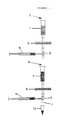
- cell reservoir 1 communicates with filtrate reservoir 7 through filter 2 and three-way valve 3.
- filtrate reservoir 7 communicates with outlet 11 through filter 8 and three-way valve 9.
- Syringes 4 and 10 are also connected respectively to three-way valves 3 and 9.
- Collection tube 12 communicates with outlet 11 to collect the purified sample.
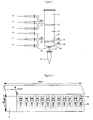
- the two chambers 21 and 27 are partitioned by filter 22. Further filter 28 acts as a barrier to prevent solid phase matrix in chamber 27 from passing to the remainder of the second chamber 30 and to the outlet 31.
- reagents from reservoirs enter at inlets 33 to 38. The inlets are all controlled by valves 23. Common ports 24 and 29 connect the reagent reservoirs with chambers 21 and 27 respectively. Vacuum lines can be applied to conduits 25 and 26. Conduits 25 and 26 act additionally as waste outlets. Collection tube 32 communicates with outlet 31 to collect the purified sample.
- a plurality of the columns can be assembled in the arrangement in Figure 3. Columns 41 and collection tubes 42 are shown. A reagent, fluid delivery and control system 43 is present to control the process in each column.
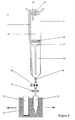
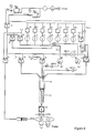
- the second column embodiment of the invention shown in Figure 5 can be used in accordance with the circuit shown in Figure 6.
- the two chambers 41 and 48 are partitioned by filter 49. Further filter 48 acts as a barrier to prevent solid phase matrix in chamber 48 from passing out of the column.
- Inlet 42 is provided in the first chamber of the column for the passage of pressurised air and also to allow air to be vented from the column.
- Inlet 43 is provided for the addition of liquids to the column.
- Conduit 47 consists of a conical portion connected to a tubular portion. Conduit 47 collects liquid from filter 46 and transfers the liquid to a collection point typically at the base of the second chamber 48. The base of the second chamber includes a conical recess to maximise liquid collection at the low volumes typically used in the apparatus.
- Line 44 is provided at the top of the second chamber for passage of pressurized air into the column and also to allow air to be vented from the column.
- a further inlet 45 is present for the addition of liquids or gas to the column and consists of a tube with an outlet located near to the bottom of the column.
- Pinch valve 50 is situated downstream of filter 49 to control flow from the second chamber and is monitored by means of liquid sensor 51.
- Indexing mechanism 54 controls the relative position of waste tube 53 or collection tube 52 according to whether liquid flowing from the column is intended for sampling or to be disposed of.
- the liquid delivery system shown in Figure 6 comprises a number of reagents in reservoirs (R1 to R8) which are pressurized typically at 0.5 bar fine pressure regulated air.
- the exact number of reagents used will depend on the exact purification protocol to be adopted.
- the reagents are divided into two blocks: reservoirs R1 to R4 contain reagents to be delivered to inlet 43 of the column and are controlled by corresponding valves 61 to 64; and reservoirs R5, R6 and R8 contain reagents to be delivered to the second chamber of the column through inlet 45 under control of valves 65 and 66.
- Reservoir R7 contains particulate matrix material to be delivered by an independent line to the top of chamber 48 through inlet 55 under control of corresponding valves 74 and 76.
- this reagent is delivered by opening valve 64 for a selected time period (e.g. 250ms). Because the reservoir is under pressure and there is a drop in pressure on the open side of valve 64, reagent enters the system until the valve closes. There is now a volume of liquid in the line from valve 64 to valve 68. The length and diameter of this line is chosen to accommodate the maximum likely volume. The volume of reagent is then moved to the top of the first chamber by switching valve 68 on and switching valve 67 on for sufficient time to allow the reagent to reach the top of the chamber. The pressure of the air forcing the liquid down the line can be either 0.5 bar or, if valve 77 is switched on, 1.7 bar. The air in front of the liquid to be moved is vented to atmosphere via valves 69 and 70. All valve timings are controlled by a microprocessor (not shown).
- Liquid flow to the column is controlled by flow constrictors C1 to C3 (0.3mm) or by using small diameter lines (0.5mm or less - say valve 80 to non-return valve NRV2).
- Non-return valves NRV1 to 4 are also incorporated in various parts of the circuit to prevent reverse flow.
- valve control is used for delivery of reagent from reservoirs R2, R3, R5 and R6.
- a volume of water is flushed through the lines from reservoir R1 in a similar manner as the delivery of reagent but the water is diverted to waste at valve 68.
- a similar function is performed for washing the lines from reservoirs R5 and R6 using water in R8 diverted to waste via valve 80.
- valve 76 is opened to allow air to escape via the vent. Because the reservoir is sealed to form a closed system, air is drawn in via non-return valve NRV4 resulting in a bubbling action sufficient to suspend matrix particles in the reagent. Valve 76 is then closed and an appropriate dose of the reagent from reservoir 7 is removed by opening pinch valve 74. The reagent is delivered to the top of the second chamber of the column by opening valve 73 and venting via valve 71.
- Buffer volumemn/prep Composition Resuspension Buffer (300 ul) 50mM Tris-HCl pH 7.5 10mM Ethylenediamine tetra acetic acid (EDTA) 100 g/ml RNase A Lysis Buffer (300 ul) 0.2M NaOH, 1% Sodium dodecylsulphate Neutralising Solution (300 ul) 2.55M Potassium acetate Matrix (500 ul) Wizard (formerly Magic) Minipreps DNA purification resin in 7M Guanidine hydrochloride Wizard and Magic Minipreps are registered trade marks of Promega Corp. Wash Buffer (2000 ul) 200mM Sodium chloride 20mM Tris-HCl, pH7.5 5mM EDTA 50% ethanol Elution Buffer (50 ul) 10mM Tris-HCl, pH7.5 1mM EDTA
- a bacterial cell culture containing plasmid DNA was added to the cell reservoir 1 at a volume of 2ml.
- the culture was filtered through filter 2 (8 micron cellulose acetate) via three-way valve 3 by means of a vacuum created by withdrawing the barrel of syringe 4 and collecting filtrate in syringe 4.
- the cells were left on the surface of the filter 2.
- Syringe 4 was disconnected, the filtrate discarded and the syringe 4 was repositioned on three-way valve 3.
- Through the opening 5 successive additions of cell resuspension buffer, cell lysis buffer and cell neutralization solution were made. Between each successive addition the cells were mixed by plunging syringe 4 to provide plenty of turbulence.
- the entire liquid phase was filtered through the filter 2 and collected in syringe 4. A solution of crude DNA was thus prepared.
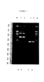
- Lane Sample M MW marker lambda/Hind III 1 pBS SKII+/pFB41B2 (Example) 2 pBS SKII+/pFB41B2 (conventional) 3 pBS SKII+ (Example) 4 pBS SKII+ (conventional) M MW marker lambda/Hind III
- the column for purifying plasmid DNA has two filters: upper lum filter 46 and lower 20um filter 49.
- the material of the filter is chosen to resist the chemicals used during the process and to have appropriate flow characteristics to allow the process to occur as quickly as possible.
- a freshly grown culture of E.coli containing a plasmid to be purified is added to chamber 41, typically 1-5ml. Addition could be made by means of removing the top or by direct addition via a tube (not shown). Positive pressure is then applied to chamber 41 by means of port 42.
- the bacteria are then filtered through filter 46 with the excess liquid passing to waste via conduit 47, filter 49 and valve 50.
- the liquid waste is monitored by flow sensor 51.
- a dose of reagent 2 (TE/RNAase) is added to the top of chamber 41 via inlet 3, typically 30 ul.
- chamber 8 is pressurised in short bursts via line 44 and pressure in chamber 41 is vented via port 42. This is done to ensure that all the cells caught on the filter are resuspended.
- a dose of reagent 3 (NaOH/SDS) is added to the top of chamber 41 via inlet 43, typically 300ul. This is then mixed as described for reagent 2.
- a dose of reagent 4 (KAcetate) is added to the top of chamber 41 via inlet 43, typically 300ul. This is then mixed as described for reagent 2.
- the resulting mixture is a cell free lysate of crude DNA with precipitated proteins.
- the cell free lysate of crude DNA is then transferred from chamber 46 to chamber 48 by addition of positive pressure via port 42, venting chamber 48 via line 44 and closing valve 50.
- a dose of reagent 7 (a DNA binding agent, e.g. silica resins, diatomaceous earth, affinity matrix) is added to chamber 48 via tube 55, typically 500ul.
- the DNA binding agent is then mixed with the crude DNA by passing air into chamber 40 via line 45. The excess liquid is then removed from chamber 48 to waste.
- the DNA is retained on the DNA binding agent which will not pass through filter 49.
- a dose of reagent 5 (50% Ethanol/NaCl) is added to chamber 48 via line 45, typically 2000ul and passed through filter 49 and removed directly to waste by means of pressurising chamber 48 with air from line 44. Air is continued to be passed through filter 49 for a period that allows the filter to dry sufficiently.
- the indexing mechanism 54 moves the collecting tube 52 so that it is in line with the exit tube from chamber 48.
- the DNA is then eluted from chamber 48 by the addition of, typically, 50ul of reagent 6(TE) via lines 45 and expelled from chamber 48 by the addition of pulses of pressure via line 44.
- the column for purifying single stranded M13 DNA has two filters: upper lum filter 46; and lower lum filter 49.
- the material of the filter is chosen to resist the chemicals used during the process and to have appropriate flow/binding characteristics to allow the process to occur as quickly as possible.
- a freshly grown culture of E.coli containing M13 to be purified is added to chamber 41, typically 1-5ml. Positive pressure is then applied to chamber 41 by means of port 42. The bacteria are then filtered through filter 46 with the excess liquid containing M13 phage passing into chamber 48 via conduit 47.
- a dose of reagent 2 (Glacial acetic acid) is added to the top of chamber 41 via inlet 43, typically 20ul.
- the phage are then filtered through filter 49 with the excess liquid passing to waste via valve 50.
- the liquid waste is monitored by flow sensor 51.
- a dose of reagent 3 (4M NaClO 4 ) is added to the top of chamber 48 via line 45, typically 1000ul.
- the filter 49 is then washed with a dose of reagent 4 (70% EtOH), typically 1000ul, and removed directly to waste by means of pressurising chamber 48 with air from line 44. Air is continued to be passed through filter 49 for a period that allows the filter to dry sufficiently.
- the indexing mechanism 54 moves the collecting tube 52 so that it is in line with the exit tube from chamber 48.
- the M13 DNA is then eluted from chamber 48 by the addition of, typically, 50ul of reagent 5 (TE) via line 45 and expelled from chamber 48 by the addition of pulses of pressure via line 44.
- TE reagent 5
- the column for the purification of genomic DNA from blood has two filters: upper filter 46 is a Leukosorb type A or B (Pall Biosurport division); and lower filter 49 is a 20um filter.
- the material of the upper filter was chosen so that it would retain nucleated cells while allowing denucleated red blood cells through.
- Freshly collected blood with EDTA as anti-coagulant was added to chamber 41 typically 1-10ml. This could be done by means of removing the top or by direct addition via a tube (not shown).
- the white blood cells are then lysed with a dose of reagent 4 (lysis buffer) which is added to the top of chamber 41 via line 43, typically 500ul. This is then mixed as described for reagent 1.
- reagent 4 lysis buffer
- the resulting mixture is a cell free lysate of crude DNA. This is then transferred from chamber 41 to chamber 48 by addition of positive pressure via port 42, venting chamber 48 via line 44 and closing valve 50.
- a dose of reagent 7 (a DNA binding agent, e.g. silica resins, diatomaceous earth, affinity matrix) is added to chamber 48 via tube 55, typically 500ul.
- the DNA binding agent is then mixed with the crude DNA by passing air into chamber 48 via line 45. The excess liquid is then removed from chamber 48 to waste.
- the DNA is retained on the DNA binding agent which will not pass through filter 49.
- a dose of reagent 5 (50% Ethanol/NaCl) is added to chamber 48 via line 45, typically 2000ul and passed through filter 49 and removed direclty to waste by means of pressurising chamber 48 with air from line 44. Air is continued to be passed through filter 49 for a period that allows the filter to dry sufficiently.
- the indexing mechanism moves the collecting tube 52 so that it is in line with the exit tube from chamber 48.
- the DNA is then eluted from chamber 48 by the addition of pulses of pressure via line 44. In between liquid additions the lines are rinsed out with water (reagent 1) via valve 68 ( Figure 6).
Landscapes
- Chemical & Material Sciences (AREA)
- Organic Chemistry (AREA)
- Life Sciences & Earth Sciences (AREA)
- Engineering & Computer Science (AREA)
- Health & Medical Sciences (AREA)
- Genetics & Genomics (AREA)
- Wood Science & Technology (AREA)
- Biotechnology (AREA)
- Bioinformatics & Cheminformatics (AREA)
- Biomedical Technology (AREA)
- Zoology (AREA)
- General Engineering & Computer Science (AREA)
- Biochemistry (AREA)
- General Health & Medical Sciences (AREA)
- Biophysics (AREA)
- Microbiology (AREA)
- Molecular Biology (AREA)
- Analytical Chemistry (AREA)
- Chemical Kinetics & Catalysis (AREA)
- Physics & Mathematics (AREA)
- Crystallography & Structural Chemistry (AREA)
- Sustainable Development (AREA)
- Plant Pathology (AREA)
- Medicinal Chemistry (AREA)
- Proteomics, Peptides & Aminoacids (AREA)
- Apparatus Associated With Microorganisms And Enzymes (AREA)
- Water Treatment By Sorption (AREA)
- Vehicle Body Suspensions (AREA)
- Electrical Discharge Machining, Electrochemical Machining, And Combined Machining (AREA)
- Saccharide Compounds (AREA)
- Micro-Organisms Or Cultivation Processes Thereof (AREA)
Claims (30)
- Verfahren zur kontinuierlichen Reinigung von Nukleinsäure von Zellen, wobei das Verfahren die folgenden Schritte umfaßt:wobei die Wände der ersten und zweiten Kammer ineinander übergehen; und(1a) Aufbringen einer rohen Zellensuspension aus einer ersten Kammer auf ein Filter zur Trennung der Zellen von dem Medium und Wiedersuspendieren der Zellen in der ersten Kammer zur Bildung einer Zellensuspension;(1b) Auflösen der Zellensuspension in der ersten Kammer zur Bildung eines Zellenlysats, das Nukleinsäure enthält;(2) Aufgeben des Zellenlysats auf das Filter zur Beseitigung unerwünschter Zellen und Zellenstücke;(3) Kontaktieren des gefilterten Lysats mit einer Feststoffmatrix, die in oder stromabwärts von einer zweiten Kammer unter solchen Bedingungen gehalten wird, daß die Nukleinsäure an der Matrix gebunden wird;(4) Trennen des erhaltenen gefilterten Lysats von der Matrix; und(5) Aufgeben von Flüssigkeit auf die Matrix durch eine Lösungszuführeinrichtung, die mit der zweiten Kammer in Verbindung steht, um die Nukleinsäure aus der Matrix durch einen Auslaß herauszulösen, der stromabwärts der Matrix vorgesehen ist;
wobei das Wiedersuspendieren der Zellen in der ersten Kammer die Zugabe eines Wiedersuspensionspuffers zu den Zellen und das Erzeugen einer Druckdifferenz am Filter zur Wiedersuspendierung der vom Filter zurückgehaltenen Zellen umfaßt, um die Zellensuspension zu bilden. - Verfahren nach Anspruch 1, bei welchem die Nukleinsäure DNA ist.
- Verfahren nach Anspruch 2, bei welchem die DNA plasmide DNA ist.
- Verfahren nach Anspruch 2, bei welchem die Zellen Blutzellen sind.
- Verfahren nach Anspruch 4, bei welchem die rohe Zellensuspension Blut enthält.
- Verfahren nach einem der vorangehenden Ansprüche, bei welchem die Feststoffmatrix durch ein zweites Filter gehalten wird.
- Verfahren nach einem der vorangehenden Ansprüche, bei welchem die Matrix und gebundene Nukleinsäure mittels Luftdurchleitung vor dem Herauslösen getrocknet werden.
- Verfahren nach einem der vorangehenden Ansprüche, bei welchem die die Nukleinsäure oder die Zielverbindung bildende Matrix gewaschen wird, um Verunreinigungen vor dem Herauslösen der Nukleinsäure oder der Zielverbindung aus der Matrix zu beseitigen.
- Verfahren nach einem der vorangehenden Ansprüche, bei welchem das Filter eine Porengröße im Bereich von 0,2 bis 50 µm besitzt.
- Verfahren nach einem der vorangehenden Ansprüche, bei welchem das Kontaktieren des gefilterten Lysats mit der Feststoffmatrix die Zugabe einer Suspension der Matrix zum gefilterten Lysat umfaßt.
- Verfahren nach einem der vorangehenden Ansprüche, bei welchem die Feststoffmatrix ein Ionenaustauschermaterial aufweist.
- Verfahren nach Anspruch 11, bei welchem das Ionenaustauschermaterial ein Anionenaustauschermaterial ist.
- Verfahren nach einem der vorangehenden Ansprüche, bei welchem die Zielverbindung oder Nukleinsäure in Lösung gehalten wird, wenn sie nicht an der Feststoffmatrix gebunden ist.
- Vorrichtung zur kontinuierlichen Reinigung einer Zielverbindung aus einer rohen Zellensuspension, welche aufweist:wobei die Wände der ersten und zweiten Kammer ineinander übergehen; undeine erste Kammer zur Aufnahme der rohen Zellensuspension, zur Aufnahme einer Zellensuspension von wiedersuspendierten Zellen und zur Aufnahme von aus aufgelöster Zellensuspension gebildetem Zellenlysat;ein Filter stromabwärts der ersten Kammer zum Abtrennen von Zellen vom Medium und Zurückhalten nichtaufgelöster Zellen und Zellenteile;eine zweite Kammer zur Aufnahme von gefiltertem Lysat stromabwärts des Filters;eine Einrichtung zum Zurückhalten einer Feststoffmatrix zum Binden der Zielverbindung, die in oder stromabwärts von der zweiten Kammer vorgesehen ist;eine Lösungszugabeeinrichtung, die mit der zweiten Kammer in Verbindung steht, zum Herauslösen der Zielverbindung aus der Matrix; undeinen Auslaß zum Abgeben der gereinigten Zielverbindung, der stromabwärts der Einrichtung zum Zurückhalten der Feststoffmatrix vorgesehen ist;
wobei eine Einrichtung zur Erzeugung einer Druckdifferenz am Filter vorgesehen ist, um vom Filter zurückgehaltene Zellen wiederzususpendieren und die Zellensuspension zu bilden. - Vorrichtung nach Anspruch 14, bei welcher die erste Kammer mit einer weiteren Einrichtung zur Zuführung von Lösungen in dieselbe in Verbindung steht.
- Vorrichtung nach Anspruch 14 oder 15, mit einer ersten Druckerzeugereinrichtung zur Erzeugung eines positiven Drucks am stromaufwärts gelegenen Ende des Filters bezüglich des stromabwärts gelegenen Endes desselben.
- Vorrichtung nach einem der Ansprüche 14 bis 16, bei welcher die Einrichtung zum Zurückhalten der Feststoffmatrix eine Sperre für die Feststoffmatrix aufweist, wobei die Sperre zwischen wenigstens einem Teil der zweiten Kammer und dem Auslaß angeordnet ist.
- Vorrichtung nach Anspruch 17, mit einer zweiten Druckerzeugereinrichtung zur Erzeugung eines positiven Drucks am stromaufwärts gelegenen Ende der Sperre bezüglich des stromabwärts gelegenen Endes derselben.
- Vorrichtung nach einem der Ansprüche 14 bis 18, bei welcher das Filter eine Porengröße im Bereich von 0,2 bis 50 µm besitzt.
- Vorrichtung nach einem der Ansprüche 14 bis 19, welche eine Fluidzuführeinrichtung mit einem Auslaß aufweist, der so angeordnet ist, daß er mit der Flüssigkeit in Verbindung steht, wenn diese in der zweiten Kammer vorhanden ist.
- Vorrichtung nach einem der Ansprüche 14 bis 20, bei welcher die zweite Kammer mit einer Einrichtung zur Zuführung einer Suspension der Feststoffmatrix in Verbindung steht.
- Vorrichtung nach einem der Ansprüche 14 bis 21, bei welcher eine Leitung zur Übertragung des Filtrats vom Filter zu einer Sammelstelle in der zweiten Kammer vorgesehen ist.
- Vorrichtung nach einem der Ansprüche 14 bis 22, bei welcher die oder jede Einrichtung zur Zuführung von Lösungen und, falls vorhanden, die Einrichtung zur Zuführung von Suspensionen und die Druckerzeugereinrichtung durch eine pneumatische Fluidzuführanlage betrieben werden, die einen kontinuierlichen Druck anwendet.
- Vorrichtung nach einem der Ansprüche 14 bis 23, mit einer Steuereinrichtung zum Koordinieren der Zuführung von Lösungen, Suspensionen und der Druckerzeugung.
- Vorrichtung nach einem der Ansprüche 14 bis 24, bei welcher die Einrichtung zur Erzeugung einer Druckdifferenz am Filter eine Fluidleitung umfaßt, um die zweite Kammer unter Druck zu setzen.
- Vorrichtung nach einem der Ansprüche 14 bis 25, bei welcher die Einrichtung zum Zurückhalten einer Feststoffmatrix ein zweites Filter aufweist.
- Vorrichtung nach einem der Ansprüche 14 bis 26, bei welcher Einrichtungen zum Trocknen der Matrix durch Luft vorgesehen sind.
- Vorrichtung nach einem der Ansprüche 14 bis 27, wenn sie in einem Verfahren nach einem der Ansprüche 1 bis 13 verwendet wird.
- Verwendung einer Vorrichtung nach einem der Ansprüche 14 bis 27 in einem Verfahren nach einem der Ansprüche 1 bis 13.
- Verfahren nach einem der Ansprüche 1 bis 13, welches unter Verwendung einer Vorrichtung nach einem der Ansprüche 14 bis 27 durchgeführt wird.
Applications Claiming Priority (3)
| Application Number | Priority Date | Filing Date | Title |
|---|---|---|---|
| GB9314249 | 1993-07-09 | ||
| GB939314249A GB9314249D0 (en) | 1993-07-09 | 1993-07-09 | Purification method and apparatus |
| PCT/GB1994/001484 WO1995002049A1 (en) | 1993-07-09 | 1994-07-08 | Purification method and apparatus |
Publications (2)
| Publication Number | Publication Date |
|---|---|
| EP0708827A1 EP0708827A1 (de) | 1996-05-01 |
| EP0708827B1 true EP0708827B1 (de) | 1998-02-04 |
Family
ID=10738562
Family Applications (1)
| Application Number | Title | Priority Date | Filing Date |
|---|---|---|---|
| EP94919795A Expired - Lifetime EP0708827B1 (de) | 1993-07-09 | 1994-07-08 | Reinigungsmethode und entsprechende vorrichtung |
Country Status (10)
| Country | Link |
|---|---|
| US (1) | US6136555A (de) |
| EP (1) | EP0708827B1 (de) |
| JP (1) | JPH09507382A (de) |
| AT (1) | ATE163043T1 (de) |
| AU (1) | AU691819B2 (de) |
| CA (1) | CA2166772A1 (de) |
| DE (1) | DE69408461T2 (de) |
| DK (1) | DK0708827T3 (de) |
| GB (1) | GB9314249D0 (de) |
| WO (1) | WO1995002049A1 (de) |
Families Citing this family (75)
| Publication number | Priority date | Publication date | Assignee | Title |
|---|---|---|---|---|
| JPH10504834A (ja) * | 1994-08-29 | 1998-05-12 | アクゾ・ノベル・エヌ・ベー | 核酸などの生物材料の単離に使用する装置 |
| JP2965131B2 (ja) | 1995-07-07 | 1999-10-18 | 東洋紡績株式会社 | 核酸結合用磁性担体およびそれを用いる核酸単離方法 |
| US6153425A (en) * | 1995-07-13 | 2000-11-28 | Xtrana, Inc. | Self-contained device integrating nucleic acid extraction, amplification and detection |
| US20040110167A1 (en) * | 1995-07-13 | 2004-06-10 | Gerdes John C. | Lateral flow system for nucleic acid detection |
| EP0814156B1 (de) * | 1996-06-18 | 2003-03-05 | The Institute Of Physical & Chemical Research | Verfahren zur Reinigung von DNS |
| FR2761373B1 (fr) * | 1997-03-28 | 1999-05-28 | Univ Angers | Procede et kit pour l'extraction d'acides nucleiques d'un echantillon biologique complexe |
| WO1999033559A1 (en) * | 1997-12-24 | 1999-07-08 | Cepheid | Integrated fluid manipulation cartridge |
| CA2304017C (en) | 1997-09-17 | 2007-05-01 | Gentra Systems, Inc. | Apparatuses and methods for isolating nucleic acid |
| US6111096A (en) * | 1997-10-31 | 2000-08-29 | Bbi Bioseq, Inc. | Nucleic acid isolation and purification |
| US7569342B2 (en) | 1997-12-10 | 2009-08-04 | Sierra Molecular Corp. | Removal of molecular assay interferences |
| DE69839734D1 (de) * | 1997-12-22 | 2008-08-28 | Hitachi Chemical Co Ltd | Direkte rt-pcr auf mikrotiterplatten mit immobilisierten oligonukleotid |
| US6844158B1 (en) | 1997-12-22 | 2005-01-18 | Hitachi Chemical Co., Ltd. | Direct RT-PCR on oligonucleotide-immobilized PCR microplates |
| JP4616990B2 (ja) * | 1998-02-02 | 2011-01-19 | キアジエン・ノース・アメリカン・ホールデイングス・インコーポレーテツド | Dnaを単離し、増幅し、そして特性化するための方法 |
| AU2574499A (en) * | 1998-02-02 | 1999-08-16 | Gentra Systems, Inc. | Compositions and methods for using a lysing matrix for isolating dna |
| JP2004500002A (ja) * | 1998-02-02 | 2004-01-08 | ジエントラ・システムズ・インコーポレーテツド | Dnaを単離するための溶出試薬、方法およびキット |
| EP2290099B1 (de) | 1998-02-02 | 2012-10-10 | QIAGEN North American Holdings, Inc. | Verfahren zur Isolierung, Amplifizierung und Charakterisierung von DNS |
| DE29803712U1 (de) | 1998-03-04 | 1998-04-23 | Macherey, Nagel GmbH & Co. Handelsgesellschaft, 52355 Düren | Vorrichtung zur Behandlung von Biomolekülen |
| US6177009B1 (en) | 1998-04-03 | 2001-01-23 | Macherey, Nagel Gmbh & Co. | Apparatus for treating biomolecules |
| GB2337261B (en) * | 1998-05-15 | 2002-09-18 | Fsm Technologies Ltd | Separation of nucleic acids |
| RU2155747C2 (ru) * | 1998-07-14 | 2000-09-10 | Воронежский государственный университет | Способ безреагентного разделения смеси тирозина и триптофана |
| DE69935232T2 (de) * | 1998-09-10 | 2008-01-10 | Whatman Plc | Produkt und Verfahren zum Auftrennen einer Probe, enthaltend genetisches Material aus mehreren Quellen, unter Verwendung eines festen Mediums |
| GB2346615B (en) | 1998-11-17 | 2003-10-15 | Cambridge Molecular Tech | Isolating nucleic acid |
| US7790865B1 (en) | 1999-02-02 | 2010-09-07 | Qiagen North American Holdings, Inc | Eluting reagents, methods and kits for isolating DNA |
| JP2003505703A (ja) * | 1999-07-23 | 2003-02-12 | テプネル・メディカル・リミテッド | 生体分子の単離 |
| AU7688900A (en) * | 1999-10-02 | 2001-05-10 | Bioneer Corporation | Automatic dna purification apparatus |
| US7517665B1 (en) * | 2000-05-03 | 2009-04-14 | Elias Hakalehto | Method and apparatus for concentrating and searching of microbiological specimens |
| WO2002016580A2 (en) * | 2000-08-24 | 2002-02-28 | Bio-Rad Laboratories, Inc. | Flow-through system for lysate clarification and nucleic acid binding in a single step |
| JP4141384B2 (ja) * | 2001-09-17 | 2008-08-27 | 株式会社日立製作所 | 試料処理装置及び試料処理方法 |
| AU2002325755A1 (en) * | 2001-09-18 | 2003-04-01 | Affinium Pharmaceuticals, Inc. | Methods and apparatuses for purification |
| US7148343B2 (en) | 2001-10-12 | 2006-12-12 | Gentra Systems, Inc. | Compositions and methods for using a solid support to purify RNA |
| US20050032105A1 (en) | 2001-10-12 | 2005-02-10 | Bair Robert Jackson | Compositions and methods for using a solid support to purify DNA |
| US7893228B2 (en) | 2001-10-12 | 2011-02-22 | Qiagen North American Holdings, Inc. | Compositions and methods for using a solid support to purify RNA |
| US20030087293A1 (en) * | 2001-10-23 | 2003-05-08 | Decode Genetics Ehf. | Nucleic acid isolation method and apparatus for performing same |
| US6833238B2 (en) | 2002-01-04 | 2004-12-21 | Applera Corporation | Petal-array support for use with microplates |
| US20050079526A1 (en) * | 2002-02-20 | 2005-04-14 | Affinium Pharmaceuticals, Inc. | Methods and apparatuses for characterizing refolding and aggregation of biological molecules |
| AU2003247276A1 (en) * | 2002-02-20 | 2003-09-09 | Affinium Pharmaceuticals, Inc. | Methods and apparatuses for characterizing stability of biological molecules |
| US6897027B2 (en) * | 2002-03-27 | 2005-05-24 | Decode Genetics Ehf. | Method for desalting nucleic acids |
| WO2003087834A2 (en) * | 2002-04-08 | 2003-10-23 | Affinium Pharmaceuticals, Inc. | High throughput analysis of recombinant proteins in multi-well plates |
| JP2005525114A (ja) * | 2002-04-24 | 2005-08-25 | ヒタチ ケミカル リサーチ センター インコーポレイテッド | 全血からのmRNAをハイスループットに定量するための装置および方法 |
| US7745180B2 (en) * | 2002-04-24 | 2010-06-29 | Hitachi Chemical Co., Ltd. | Device and method for high-throughput quantification of mRNA from whole blood |
| EP1527172B1 (de) * | 2002-05-17 | 2008-11-26 | Molzym GmbH & Co. KG | Methode für die extraktion und aufreinigung von nukleinsäuren |
| US20040018559A1 (en) * | 2002-07-26 | 2004-01-29 | Applera Corporation | Size-exclusion ion-exchange particles |
| US20040121445A1 (en) * | 2002-07-31 | 2004-06-24 | Fabien Marino | Cell cultures |
| US20040110132A1 (en) * | 2002-12-06 | 2004-06-10 | Affymetrix, Inc. | Method for concentrate nucleic acids |
| ATE531817T1 (de) * | 2003-07-15 | 2011-11-15 | Lukas Bestmann | Probenzubereitungseinheit |
| EP1508792B1 (de) * | 2003-08-19 | 2012-11-28 | Kurashiki Boseki Kabushiki Kaisha | Vorrichtung zur Extraktion von Nukleinsäuren |
| JP2005095160A (ja) * | 2003-08-19 | 2005-04-14 | Fuji Photo Film Co Ltd | 抽出装置用ラック |
| EP1508375A3 (de) * | 2003-08-19 | 2006-04-05 | Fuji Photo Film Co., Ltd. | Ständer für Extraktionsvorrichtungen |
| US7115719B2 (en) | 2003-12-16 | 2006-10-03 | Gentra Systems, Inc. | Formulations and methods for denaturing proteins |
| US20060160122A1 (en) * | 2004-02-18 | 2006-07-20 | Applera Corporation | Polyelectrolyte-coated size-exclusion ion-exchange particles |
| US20050181378A1 (en) * | 2004-02-18 | 2005-08-18 | Applera Corporation | Polyelectrolyte-coated size-exclusion ion-exchange particles |
| US20050196856A1 (en) * | 2004-02-18 | 2005-09-08 | Applera Corporation | Polyelectrolyte-coated size-exclusion ion-exchange particles |
| JP4399304B2 (ja) * | 2004-03-29 | 2010-01-13 | 富士フイルム株式会社 | 自動核酸分離精製方法およびその装置 |
| US8053214B2 (en) * | 2004-09-09 | 2011-11-08 | Microfluidic Systems, Inc. | Apparatus and method of extracting and optically analyzing an analyte from a fluid-based sample |
| WO2006029387A1 (en) * | 2004-09-09 | 2006-03-16 | Microfluidic Systems Inc. | A handheld and portable microfluidic device to automatically prepare nucleic acids for analysis |
| US20060105372A1 (en) | 2004-11-05 | 2006-05-18 | Bair Robert J | Compositions and methods for purifying nucleic acids from stabilization reagents |
| DE102005051645B4 (de) | 2005-10-26 | 2018-10-18 | Rapid Sampling Technologies Ag | Einrichtung zur Fraktionierung von mit Partikeln beladenen Flüssigkeiten |
| US20070141605A1 (en) * | 2005-11-21 | 2007-06-21 | Applera Corporation | Portable preparation, analysis, and detection apparatus for nucleic acid processing |
| WO2007100986A2 (en) * | 2006-02-24 | 2007-09-07 | Rosetta Inpharmatics Llc | Extraction and diagnostic fluid devices, systems and methods of use |
| US20100216657A1 (en) * | 2006-05-16 | 2010-08-26 | Arcxis Biotechnologies, Inc. | Pcr-free sample preparation and detection systems for high speed biologic analysis and identification |
| TW200800318A (en) * | 2006-06-15 | 2008-01-01 | Antera Biotech Corp | Synchronous injection mechanism for common liquid |
| US20080131955A1 (en) * | 2006-11-30 | 2008-06-05 | Canon U.S. Life Sciences, Inc. | Method of Separating Target DNA from Mixed DNA |
| US8032258B2 (en) * | 2007-12-04 | 2011-10-04 | Ludwig Lester F | Multi-channel chemical transport bus for microfluidic and other applications |
| US8158405B2 (en) * | 2008-06-30 | 2012-04-17 | General Electric Company | Process for concentrating and processing fluid samples |
| US20110313143A1 (en) * | 2008-12-15 | 2011-12-22 | Life Technologies Corporation | Nucleic acid purification apparatus and method |
| GB2469266A (en) * | 2009-04-06 | 2010-10-13 | Romney John Hanning Jackson | Device for the isolation of nucleic acids in a sealed environment |
| WO2010130310A1 (en) * | 2009-05-15 | 2010-11-18 | Fraunhofer-Gesellschaft zur Förderung der angewandten Forschung e.V. | Pipette head with filter and flushing means |
| CA2802430C (en) * | 2010-07-20 | 2021-07-20 | Bavarian Nordic A/S | Method for harvesting poxvirus |
| CN103748208A (zh) | 2011-07-01 | 2014-04-23 | 恰根有限公司 | 生物分子分离中的过滤器模块 |
| JP2015507602A (ja) * | 2011-09-30 | 2015-03-12 | ジーイー・ヘルスケア・リミテッド | 区画反応器 |
| CN103974762A (zh) * | 2011-09-30 | 2014-08-06 | 通用电气健康护理有限公司 | 用于多步放射化学的反应器 |
| US9670479B2 (en) | 2013-03-15 | 2017-06-06 | F Cubed, LLC | Sample preparation device and methods of use |
| US9758755B2 (en) * | 2015-10-23 | 2017-09-12 | Life Technologies Corporation | Filter-based method for efficient capture of lysis of suspended cells |
| US10634591B2 (en) * | 2017-03-13 | 2020-04-28 | Tokitae Llc | Device for concentration of biological sample prior to immunoassay |
| KR102136695B1 (ko) * | 2018-08-22 | 2020-07-22 | 주식회사 인퓨전텍 | 현장 진단용 장치를 이용한 병원체 농축 및 핵산 추출 방법 |
Family Cites Families (16)
| Publication number | Priority date | Publication date | Assignee | Title |
|---|---|---|---|---|
| US4493815A (en) * | 1983-07-28 | 1985-01-15 | Bio-Rad Laboratories, Inc. | Supporting and filtering biochemical test plate assembly |
| GB8613476D0 (en) * | 1986-06-04 | 1986-07-09 | London Hospital Med Coll | Method of sequencing nucleic acids |
| US4895706A (en) * | 1986-10-28 | 1990-01-23 | Costar Corporation | Multi-well filter strip and composite assemblies |
| DE3639949A1 (de) * | 1986-11-22 | 1988-06-09 | Diagen Inst Molekularbio | Verfahren zur trennung von langkettigen nukleinsaeuren |
| JP2862547B2 (ja) * | 1987-03-02 | 1999-03-03 | ジエン―プローブ・インコーポレイテツド | 核酸精製、分離及びハイブリダイゼーション用ポリカチオン性支持体 |
| SE8801098D0 (sv) * | 1988-03-24 | 1988-03-24 | Pharmacia Ab | Apparatus and method for automatic extraction of extra-chromosomal dna from a cell suspension in a container |
| IE883226L (en) * | 1988-10-25 | 1990-04-25 | Dna Prep Galway Ltd S 22 | Separation of nucleic acids from protein material using¹cation exchangers |
| IT1226210B (it) * | 1988-12-22 | 1990-12-21 | Claudio Schneider | Procedimento per l'estrazione e la purificazione di dna |
| NL8900725A (nl) * | 1989-03-23 | 1990-10-16 | Az Univ Amsterdam | Werkwijze en combinatie van middelen voor het isoleren van nucleinezuur. |
| US4997932A (en) * | 1989-11-13 | 1991-03-05 | Boehringer Mannheim Corporation | Method and kit for purifying nucleic acids |
| SE9002579D0 (sv) * | 1990-08-07 | 1990-08-07 | Pharmacia Ab | Method and apparatus for carrying out biochemical reactions |
| DE4034036C2 (de) * | 1990-10-26 | 1994-03-03 | Diagen Inst Molekularbio | Vorrichtung und Verfahren zur Isolierung von Nukleinsäuren aus Zellsuspensionen |
| US5264184A (en) * | 1991-03-19 | 1993-11-23 | Minnesota Mining And Manufacturing Company | Device and a method for separating liquid samples |
| US5395521A (en) * | 1991-05-31 | 1995-03-07 | Board Of Regents, The University Of Texas System | Automated column equilibration, column loading, column washing and column elution |
| JPH04360686A (ja) * | 1991-06-04 | 1992-12-14 | Tosoh Corp | Dnaの精製方法 |
| DE4143639C2 (de) * | 1991-12-02 | 2002-10-24 | Qiagen Gmbh | Verfahren zur Isolierung und Reinigung von Nukleinsäuren |
-
1993
- 1993-07-09 GB GB939314249A patent/GB9314249D0/en active Pending
-
1994
- 1994-07-08 AU AU70812/94A patent/AU691819B2/en not_active Ceased
- 1994-07-08 DK DK94919795T patent/DK0708827T3/da active
- 1994-07-08 DE DE69408461T patent/DE69408461T2/de not_active Expired - Fee Related
- 1994-07-08 JP JP7503926A patent/JPH09507382A/ja active Pending
- 1994-07-08 US US08/571,864 patent/US6136555A/en not_active Expired - Fee Related
- 1994-07-08 CA CA002166772A patent/CA2166772A1/en not_active Abandoned
- 1994-07-08 WO PCT/GB1994/001484 patent/WO1995002049A1/en not_active Ceased
- 1994-07-08 EP EP94919795A patent/EP0708827B1/de not_active Expired - Lifetime
- 1994-07-08 AT AT94919795T patent/ATE163043T1/de not_active IP Right Cessation
Also Published As
| Publication number | Publication date |
|---|---|
| CA2166772A1 (en) | 1995-01-19 |
| EP0708827A1 (de) | 1996-05-01 |
| JPH09507382A (ja) | 1997-07-29 |
| US6136555A (en) | 2000-10-24 |
| DE69408461D1 (de) | 1998-03-12 |
| AU7081294A (en) | 1995-02-06 |
| GB9314249D0 (en) | 1993-08-18 |
| WO1995002049A1 (en) | 1995-01-19 |
| DE69408461T2 (de) | 1998-08-20 |
| DK0708827T3 (da) | 1998-09-23 |
| AU691819B2 (en) | 1998-05-28 |
| ATE163043T1 (de) | 1998-02-15 |
Similar Documents
| Publication | Publication Date | Title |
|---|---|---|
| AU691819B2 (en) | Purification method and apparatus | |
| US8680261B2 (en) | Methods for purifying nucleic acids | |
| US6986848B2 (en) | Apparatus for purifying nucleic acids and proteins | |
| EP0407444B1 (de) | Vorrichtung und verfahren zur selbsttätigen reinigung von extrachromosomen dns aus einer zellsuspension in einem behälter | |
| EP1018549B1 (de) | Methode zur dns-isolierung. | |
| AU778440B2 (en) | Sample processing device | |
| EP1873243A1 (de) | Isolierung von RNA und DNA aus einer biologischen Probe | |
| EP1203080B1 (de) | Isolierung von biomolekülen | |
| KR20120044918A (ko) | 핵산 정제 | |
| AU2001260507B2 (en) | Nucleic acid isolation | |
| EP0245945B1 (de) | Automatisches Gerät zum Extrahieren von Nukleinsäuren | |
| WO2004024283A2 (en) | Apparatus and method for preparative scale purification of nucleic acids | |
| CA1335963C (en) | Automated nucleic acid extractor | |
| EP0432162A1 (de) | Apparat und verfahren zur automatischen abtrennung von extrachromosomaler dns aus einer zellsuspension. | |
| JP3547715B2 (ja) | ベクター精製用装置及び方法 | |
| EP4206324A1 (de) | Reinigung von makromolekülen | |
| US20030087293A1 (en) | Nucleic acid isolation method and apparatus for performing same | |
| AU2002363042A1 (en) | Nucleic acid isolation method and apparatus for performing same |
Legal Events
| Date | Code | Title | Description |
|---|---|---|---|
| PUAI | Public reference made under article 153(3) epc to a published international application that has entered the european phase |
Free format text: ORIGINAL CODE: 0009012 |
|
| 17P | Request for examination filed |
Effective date: 19960207 |
|
| AK | Designated contracting states |
Kind code of ref document: A1 Designated state(s): AT BE CH DE DK ES FR GB IT LI NL PT SE |
|
| 17Q | First examination report despatched |
Effective date: 19960614 |
|
| GRAG | Despatch of communication of intention to grant |
Free format text: ORIGINAL CODE: EPIDOS AGRA |
|
| GRAG | Despatch of communication of intention to grant |
Free format text: ORIGINAL CODE: EPIDOS AGRA |
|
| GRAH | Despatch of communication of intention to grant a patent |
Free format text: ORIGINAL CODE: EPIDOS IGRA |
|
| RAP1 | Party data changed (applicant data changed or rights of an application transferred) |
Owner name: CAMBRIDGE MOLECULAR TECHNOLOGIES LIMITED |
|
| GRAH | Despatch of communication of intention to grant a patent |
Free format text: ORIGINAL CODE: EPIDOS IGRA |
|
| GRAA | (expected) grant |
Free format text: ORIGINAL CODE: 0009210 |
|
| AK | Designated contracting states |
Kind code of ref document: B1 Designated state(s): AT BE CH DE DK ES FR GB IT LI NL PT SE |
|
| PG25 | Lapsed in a contracting state [announced via postgrant information from national office to epo] |
Ref country code: ES Free format text: THE PATENT HAS BEEN ANNULLED BY A DECISION OF A NATIONAL AUTHORITY Effective date: 19980204 |
|
| REF | Corresponds to: |
Ref document number: 163043 Country of ref document: AT Date of ref document: 19980215 Kind code of ref document: T |
|
| REG | Reference to a national code |
Ref country code: CH Ref legal event code: EP |
|
| REF | Corresponds to: |
Ref document number: 69408461 Country of ref document: DE Date of ref document: 19980312 |
|
| ITF | It: translation for a ep patent filed | ||
| PG25 | Lapsed in a contracting state [announced via postgrant information from national office to epo] |
Ref country code: PT Free format text: LAPSE BECAUSE OF FAILURE TO SUBMIT A TRANSLATION OF THE DESCRIPTION OR TO PAY THE FEE WITHIN THE PRESCRIBED TIME-LIMIT Effective date: 19980504 |
|
| ET | Fr: translation filed | ||
| REG | Reference to a national code |
Ref country code: DK Ref legal event code: T3 |
|
| PLBE | No opposition filed within time limit |
Free format text: ORIGINAL CODE: 0009261 |
|
| STAA | Information on the status of an ep patent application or granted ep patent |
Free format text: STATUS: NO OPPOSITION FILED WITHIN TIME LIMIT |
|
| 26N | No opposition filed | ||
| PGFP | Annual fee paid to national office [announced via postgrant information from national office to epo] |
Ref country code: SE Payment date: 19990616 Year of fee payment: 6 |
|
| PGFP | Annual fee paid to national office [announced via postgrant information from national office to epo] |
Ref country code: FR Payment date: 19990630 Year of fee payment: 6 Ref country code: BE Payment date: 19990630 Year of fee payment: 6 |
|
| PGFP | Annual fee paid to national office [announced via postgrant information from national office to epo] |
Ref country code: GB Payment date: 19990705 Year of fee payment: 6 |
|
| PGFP | Annual fee paid to national office [announced via postgrant information from national office to epo] |
Ref country code: CH Payment date: 19990715 Year of fee payment: 6 |
|
| PGFP | Annual fee paid to national office [announced via postgrant information from national office to epo] |
Ref country code: DK Payment date: 19990729 Year of fee payment: 6 |
|
| PGFP | Annual fee paid to national office [announced via postgrant information from national office to epo] |
Ref country code: NL Payment date: 19990730 Year of fee payment: 6 Ref country code: AT Payment date: 19990730 Year of fee payment: 6 |
|
| PGFP | Annual fee paid to national office [announced via postgrant information from national office to epo] |
Ref country code: DE Payment date: 19990825 Year of fee payment: 6 |
|
| PG25 | Lapsed in a contracting state [announced via postgrant information from national office to epo] |
Ref country code: GB Free format text: LAPSE BECAUSE OF NON-PAYMENT OF DUE FEES Effective date: 20000708 Ref country code: AT Free format text: LAPSE BECAUSE OF NON-PAYMENT OF DUE FEES Effective date: 20000708 |
|
| PG25 | Lapsed in a contracting state [announced via postgrant information from national office to epo] |
Ref country code: SE Free format text: LAPSE BECAUSE OF NON-PAYMENT OF DUE FEES Effective date: 20000709 |
|
| PG25 | Lapsed in a contracting state [announced via postgrant information from national office to epo] |
Ref country code: LI Free format text: LAPSE BECAUSE OF NON-PAYMENT OF DUE FEES Effective date: 20000731 Ref country code: DK Free format text: LAPSE BECAUSE OF NON-PAYMENT OF DUE FEES Effective date: 20000731 Ref country code: CH Free format text: LAPSE BECAUSE OF NON-PAYMENT OF DUE FEES Effective date: 20000731 Ref country code: BE Free format text: LAPSE BECAUSE OF NON-PAYMENT OF DUE FEES Effective date: 20000731 |
|
| BERE | Be: lapsed |
Owner name: CAMBRIDGE MOLECULAR TECHNOLOGIES LTD Effective date: 20000731 |
|
| PG25 | Lapsed in a contracting state [announced via postgrant information from national office to epo] |
Ref country code: NL Free format text: LAPSE BECAUSE OF NON-PAYMENT OF DUE FEES Effective date: 20010201 |
|
| GBPC | Gb: european patent ceased through non-payment of renewal fee |
Effective date: 20000708 |
|
| REG | Reference to a national code |
Ref country code: DK Ref legal event code: EBP |
|
| REG | Reference to a national code |
Ref country code: CH Ref legal event code: PL |
|
| EUG | Se: european patent has lapsed |
Ref document number: 94919795.8 |
|
| PG25 | Lapsed in a contracting state [announced via postgrant information from national office to epo] |
Ref country code: FR Free format text: LAPSE BECAUSE OF NON-PAYMENT OF DUE FEES Effective date: 20010330 |
|
| NLV4 | Nl: lapsed or anulled due to non-payment of the annual fee |
Effective date: 20010201 |
|
| REG | Reference to a national code |
Ref country code: FR Ref legal event code: ST |
|
| PG25 | Lapsed in a contracting state [announced via postgrant information from national office to epo] |
Ref country code: DE Free format text: LAPSE BECAUSE OF NON-PAYMENT OF DUE FEES Effective date: 20010501 |
|
| PG25 | Lapsed in a contracting state [announced via postgrant information from national office to epo] |
Ref country code: IT Free format text: LAPSE BECAUSE OF NON-PAYMENT OF DUE FEES;WARNING: LAPSES OF ITALIAN PATENTS WITH EFFECTIVE DATE BEFORE 2007 MAY HAVE OCCURRED AT ANY TIME BEFORE 2007. THE CORRECT EFFECTIVE DATE MAY BE DIFFERENT FROM THE ONE RECORDED. Effective date: 20050708 |