EP0708996B1 - Slab-laser mit gefalteter resonatorstruktur - Google Patents
Slab-laser mit gefalteter resonatorstruktur Download PDFInfo
- Publication number
- EP0708996B1 EP0708996B1 EP94925669A EP94925669A EP0708996B1 EP 0708996 B1 EP0708996 B1 EP 0708996B1 EP 94925669 A EP94925669 A EP 94925669A EP 94925669 A EP94925669 A EP 94925669A EP 0708996 B1 EP0708996 B1 EP 0708996B1
- Authority
- EP
- European Patent Office
- Prior art keywords
- mirrors
- resonator
- mirror
- axis
- laser according
- Prior art date
- Legal status (The legal status is an assumption and is not a legal conclusion. Google has not performed a legal analysis and makes no representation as to the accuracy of the status listed.)
- Expired - Lifetime
Links
- 230000008878 coupling Effects 0.000 claims description 7
- 238000010168 coupling process Methods 0.000 claims description 7
- 238000005859 coupling reaction Methods 0.000 claims description 7
- 238000013461 design Methods 0.000 description 38
- 239000007789 gas Substances 0.000 description 11
- CURLTUGMZLYLDI-UHFFFAOYSA-N Carbon dioxide Chemical compound O=C=O CURLTUGMZLYLDI-UHFFFAOYSA-N 0.000 description 10
- 230000004075 alteration Effects 0.000 description 7
- 150000001875 compounds Chemical class 0.000 description 7
- 230000008901 benefit Effects 0.000 description 6
- 239000001569 carbon dioxide Substances 0.000 description 5
- 229910002092 carbon dioxide Inorganic materials 0.000 description 5
- 230000003287 optical effect Effects 0.000 description 3
- 239000007787 solid Substances 0.000 description 3
- 238000010408 sweeping Methods 0.000 description 3
- 238000013459 approach Methods 0.000 description 2
- 230000000694 effects Effects 0.000 description 2
- 239000000463 material Substances 0.000 description 2
- IJGRMHOSHXDMSA-UHFFFAOYSA-N Atomic nitrogen Chemical compound N#N IJGRMHOSHXDMSA-UHFFFAOYSA-N 0.000 description 1
- XAGFODPZIPBFFR-UHFFFAOYSA-N aluminium Chemical compound [Al] XAGFODPZIPBFFR-UHFFFAOYSA-N 0.000 description 1
- 229910052782 aluminium Inorganic materials 0.000 description 1
- 230000008859 change Effects 0.000 description 1
- 230000001427 coherent effect Effects 0.000 description 1
- 230000001627 detrimental effect Effects 0.000 description 1
- 238000011161 development Methods 0.000 description 1
- 229910003460 diamond Inorganic materials 0.000 description 1
- 239000010432 diamond Substances 0.000 description 1
- 239000001307 helium Substances 0.000 description 1
- 229910052734 helium Inorganic materials 0.000 description 1
- SWQJXJOGLNCZEY-UHFFFAOYSA-N helium atom Chemical compound [He] SWQJXJOGLNCZEY-UHFFFAOYSA-N 0.000 description 1
- 230000006872 improvement Effects 0.000 description 1
- 238000013383 initial experiment Methods 0.000 description 1
- 238000013101 initial test Methods 0.000 description 1
- 239000000203 mixture Substances 0.000 description 1
- 238000012986 modification Methods 0.000 description 1
- 230000004048 modification Effects 0.000 description 1
- JCXJVPUVTGWSNB-UHFFFAOYSA-N nitrogen dioxide Inorganic materials O=[N]=O JCXJVPUVTGWSNB-UHFFFAOYSA-N 0.000 description 1
- 230000005855 radiation Effects 0.000 description 1
- 238000011160 research Methods 0.000 description 1
- 230000035945 sensitivity Effects 0.000 description 1
- 229910052724 xenon Inorganic materials 0.000 description 1
- FHNFHKCVQCLJFQ-UHFFFAOYSA-N xenon atom Chemical compound [Xe] FHNFHKCVQCLJFQ-UHFFFAOYSA-N 0.000 description 1
Images


Classifications
-
- H—ELECTRICITY
- H01—ELECTRIC ELEMENTS
- H01S—DEVICES USING THE PROCESS OF LIGHT AMPLIFICATION BY STIMULATED EMISSION OF RADIATION [LASER] TO AMPLIFY OR GENERATE LIGHT; DEVICES USING STIMULATED EMISSION OF ELECTROMAGNETIC RADIATION IN WAVE RANGES OTHER THAN OPTICAL
- H01S3/00—Lasers, i.e. devices using stimulated emission of electromagnetic radiation in the infrared, visible or ultraviolet wave range
- H01S3/02—Constructional details
- H01S3/03—Constructional details of gas laser discharge tubes
- H01S3/0315—Waveguide lasers
-
- H—ELECTRICITY
- H01—ELECTRIC ELEMENTS
- H01S—DEVICES USING THE PROCESS OF LIGHT AMPLIFICATION BY STIMULATED EMISSION OF RADIATION [LASER] TO AMPLIFY OR GENERATE LIGHT; DEVICES USING STIMULATED EMISSION OF ELECTROMAGNETIC RADIATION IN WAVE RANGES OTHER THAN OPTICAL
- H01S3/00—Lasers, i.e. devices using stimulated emission of electromagnetic radiation in the infrared, visible or ultraviolet wave range
- H01S3/05—Construction or shape of optical resonators; Accommodation of active medium therein; Shape of active medium
- H01S3/08—Construction or shape of optical resonators or components thereof
- H01S3/081—Construction or shape of optical resonators or components thereof comprising three or more reflectors
-
- H—ELECTRICITY
- H01—ELECTRIC ELEMENTS
- H01S—DEVICES USING THE PROCESS OF LIGHT AMPLIFICATION BY STIMULATED EMISSION OF RADIATION [LASER] TO AMPLIFY OR GENERATE LIGHT; DEVICES USING STIMULATED EMISSION OF ELECTROMAGNETIC RADIATION IN WAVE RANGES OTHER THAN OPTICAL
- H01S3/00—Lasers, i.e. devices using stimulated emission of electromagnetic radiation in the infrared, visible or ultraviolet wave range
- H01S3/09—Processes or apparatus for excitation, e.g. pumping
- H01S3/097—Processes or apparatus for excitation, e.g. pumping by gas discharge of a gas laser
- H01S3/0975—Processes or apparatus for excitation, e.g. pumping by gas discharge of a gas laser using inductive or capacitive excitation
Definitions
- This invention relates to a laser comprising:
- this type of laser preferably includes a pair of planar, rectangular electrodes, spaced apart in a manner to define a slab discharge region.
- the slab discharge region has a narrow axis extending between the electrodes and a wider axis extending parallel to the electrode surfaces.
- the narrow axis defines a waveguide channel between the electrodes.
- a lasing gas such as carbon dioxide, is located between the electrodes.
- a means is provided for energizing the electrodes to excite the gas.
- the lasing gas is excited with an RF generator.
- a mirror is positioned adjacent each end of the electrodes to define the resonator.
- a hybrid resonator In order to maximize the power output and enhance stability in a slab laser, it is desirable to employ a "hybrid" resonator.
- a hybrid resonator In a hybrid resonator, the propagation of light in one axis is different from the propagation of light in the other axis.
- a stable waveguide resonator In contrast, in the wider axis, a free-space resonator is defined. Where the width of the wider axis is a few centimeters or more, the free-space resonator is defined by an unstable resonator. In the preferred design, a negative branch unstable resonator is used.
- one of the end mirrors of the resonator is slightly shorter than the other end mirror, so that laser beam can be "edge coupled" out of the resonator.
- EP-A-0 355 757 describes a slab laser using a gas as the lasing medium and having an oscillator stage, in the form of an unstable resonator with one mirror at each end, followed by an amplifier stage in which the laser beam is folded by reflection between two opposed pairs of flat mirror surfaces, the mirror surfaces of each pair being at an angle to each other, and the amplified beam emerging from the amplifier through a gap between the mirror surfaces of one such pair.
- Coherent, Inc. has successfully marketed lasers designed in accordance with U.S. patent no. 5 123 028, both for use in medical systems (sold under the trade mark “Ultrapulse”) and for industrial applications (sold under the trade mark “Diamond”). Significant research activity has continued in order to further improve this product.
- the resonator mirrors are mounted to the ends of a sealed laser housing.
- the length of the housing, and hence the length of the resonator will vary.
- mode sweeping As the length of the resonator varies, different longitudinal modes of the laser will oscillate in a phenomenon referred to as mode sweeping. It has been found that this mode sweeping phenomenon can result in power fluctuations in excess of ten percent and as much as fifteen percent. These power fluctuations can be detrimental for both medical and industrial applications.
- a laser of the kind defined hereinbefore at the beginning is characterised in that there are at least two of the mirrors at each opposed end of the slab shaped gain region, and in that the orientation and curvature of the mirrors are such that the mirrors cooperate to fold the beam along multiple paths in the wide axis and to provide a focal point located between every pair of the mirrors that bounds a beam path.
- An embodiment of the present invention has a unique resonator design wherein the beam path is folded in the wide or free-space axis.
- two mirrors are located at each end of the electrodes.
- a folded path is defined which causes the beam to traverse the discharge space six times as compared to only twice in the prior art design.
- the number of longitudinal modes which can oscillate within the laser is similarly increased.
- the fluctuations in power associated with the variations in the length of the resonator are substantially reduced.
- fluctuations in power with the subject resonator were less than one percent as compared to the ten to fifteen percent associated with the standard resonator design.
- the three-fold increase in the number of times the beam passes through the gain region can also lead to an increase in operating efficiency.
- the curvature and orientation of the mirrors are selected to define a compound resonator, wherein the mirrors bounding each path define separate resonator-like structures.
- the propagation between each mirror pair defines a stable waveguide in the narrow axis and a negative branch unstable configuration in the wide axis.
- the mirrors are arranged in a confocal relationship which creates a focus between the mirror pairs. This unique compound resonator leads to enhanced alignment stability.
- Another advantageous preferred feature allows the beam to be coupled out of the center of the laser, rather than at an edge.
- a space is provided between one of the pairs of mirrors located at one end of the electrodes. In this configuration, the laser beam is coupled out of the resonator through the space between the mirrors.
- the subject resonator can be modified to include three or more mirrors at each end of the electrodes, creating a greater number of folds.
- the width of the electrodes can be easily increased so that the power output per unit length can be increased.
- Figure 1 is a perspective schematic illustration of an RF excited, slab waveguide resonator including the compound resonator of the subject invention.
- Figure 2 is a schematic illustration of the folded path of the laser beam, with Figure 2a showing the first two paths, Figures 2b and 2c showing the third and fourth paths respectively, and Figure 2d illustrating the fifth and sixth paths and the outcoupling of the beam from the resonator.
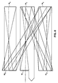
- Figure 3 is an illustration similar to Figure 2 wherein all of the paths of the beam are illustrated in a single view.
- Figure 4 is an illustration of a four mirror resonator where the beam path is unfolded to illustrate a linear progression.
- Figure 5 is an illustration similar to Figure 3 except that the beam is shown coupled out along the outside edge of the discharge region.
- Figure 6 is an illustration of the beam path in a six mirror resonator design wherein three mirrors are located at each end of the discharge region and the beam is coupled out past the inner edge of outer mirrors.
- Figure 7 shows the resonator of Figure 6 with the beam path unfolded.
- Figure 8 is an illustration similar to Figure 6 of a six mirror resonator design wherein the beam is coupled out past the edge of one of the inner mirrors.
- Figure 9 is an illustration of the beam path in an eight mirror resonator design wherein four mirrors are located at each end of the discharge region.
- Figures 10 through 15 illustrate a preferred embodiment for mounting a pair of mirrors at the end of the electrodes in a sealed gas laser.
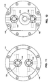
- Figure 10 is a cross-sectional view looking down onto the top of the upper electrode.
- Figure 11 is an elevational view from the right hand side of Figure 10.
- Figure 12 is an elevational view from the left hand side of Figure 10.
- Figure 13 is a cross-sectional view taken along the line 13-13 in Figure 10.
- Figure 14 is a cross-sectional view taken along the line 14-14 in Figure 10.
- Figure 15 is an exploded perspective view of the end cap 114 shown in Figure 10.
- a laser 10 having a pair of elongated, rectangular planar electrodes 12 and 14.
- the electrodes are positioned in a manner to define a discharge region 16 which has a slab or rectangular configuration.
- the spacing S between the electrodes is relatively small and defines the waveguide axis. This spacing is typically on the order of 2mm.
- the width W of the electrodes is significantly larger, on the order of 4 to 5cm.
- a lasing gas is disposed in the discharge region 16.
- the electrodes are mounted in a sealed housing which also contains carbon dioxide as the lasing gas.
- the gas is excited by an RF generator 20 which is connected to the electrodes through a suitable matching network (not shown). Additional details about the design of the laser can be obtained by referring to U.S. Patent No. 5,123,028.
- the resonator is defined by mounting a first mirror adjacent one end of the electrodes and a second mirror adjacent the other end of the mirror.
- spherical mirrors were selected in a manner to define a hybrid resonator. More specifically, a waveguide resonator (where the propagation of light is controlled by the electrode surfaces) is defined in the narrow axis. In contrast, a negative branch unstable resonator (where light propagation is only controlled by the mirrors) is defined in the wider axis. The basic principles of this hybrid design are carried forth in the preferred embodiment of the subject invention.
- a pair of mirrors 30, 34 and 32, 36 are located at each end of the electrodes 12, 14. Assuming that the width of the electrodes is the same as in the prior art design, the width of each mirror 30-36 would be roughly half the width of the prior mirrors.
- the curvature and orientation of the mirrors are arranged so that beam path is folded in the wide or free-space axis of the laser. This fold pattern can be contrasted with other prior art efforts to fold the beam in the waveguide axis.
- the beam path within the resonator can be considered a two pass configuration.
- the beam will traverse the discharge region six times, effectively increasing the path length by a factor of three which provides a number of benefits discussed in greater detail below.
- Figures 2a to 2d illustrate the folded beam path. These views are a top plan representations of the laser illustrated in Figure 1 and show the propagation of the beam in the free space axis. As noted above, in the narrow axis, the beam propagates in the waveguide mode. In these drawings, the mirrors appear planar but are actually spherical.
- the beam 40 is shown originating on mirror 30 and moving along a first direction, to mirror 32 and through a first focus F 1 .
- the beam 40 then reflects off mirror 32 and is directed downwardly to mirror 34 in a substantially collimated fashion. It should be appreciated that if mirror 32 had been tilted upwardly so that the second pass was directed towards mirror 30, the beam propagation characteristics would be identical to the prior art, two mirror, negative branch unstable resonator design. By using mirror curvatures and positioning which maintains the characteristics of the negative branch unstable resonator through each pass, alignment stability is not sacrificed even though the beam is folded into a multiple passes.
- Figure 2b illustrates the third pass of the beam from mirror 34 to mirror 36.
- the beam comes to a second focus at point F 2 .
- Figure 2c illustrates the collimated beam returning to mirror 34.
- the beam is directed from mirror 34 back up to mirror 32.
- the beam is focused at point F 3 .
- the beam is then reflected back towards mirror 34 in substantially collimated fashion.
- the width of the beam will increase upon each pass due to the magnification provided by the curvature of the mirrors.
- beam 40 reaches mirror 30 as shown in Figure 2d, its width will be greater than when it first originated from that mirror surface. For this reason, the beam can be coupled out of the resonator along the edge of mirror 30 in a well known edge coupled manner.
- the length L of mirror 30 is less than the length of the other mirrors.
- mirror 30 is positioned such that a space is defined between mirror 30 and the adjacent mirror 34.
- Coupling out of the center of the discharge space can provide some practical advantages. More specifically, it is often easier to design optical systems for a beam that is coupled out of the center of a laser housing. In addition, by coupling out near the center of the discharge, diffraction effects from the edge of the slab can be avoided.
- the center coupling approach is particularly preferred for use with the resonator of the subject invention because it helps to simplify the mounting of mirror 30. More specifically, if a resonator were configured so that the beam is coupled past the outer edge of mirror 30 (as in Figure 5, below), the accuracy of the position of both the inner and outer edges of mirror 30 would be critical. The outer edge of mirror 30 must be accurately located to properly couple the beam out of the resonator. In addition, the inner edge of mirror 30 must be positioned accurately with respect to mirror 34 (See Figure 5).
- mirror 30 In contrast, in a center coupling configuration, only the inner edge of mirror 30 needs to be accurately positioned.
- the outer edge of mirror 30 (just like the outer edges of mirrors 32, 34 and 36) simply extends beyond the discharge region and beyond the beam path and therefore the position of the outer edge is not critical.
- One significant advantage to the subject folded resonator design disclosed herein is that the multiple beam path increases the length of the resonant cavity without increasing the size of the discharge region.
- the number of longitudinal modes which can be supported by an oscillator is directly proportional to the length of the cavity.
- the number of longitudinal modes which can oscillate will also be tripled.
- the increase in the number of longitudinal modes significantly improves the power stability performance of the laser. More specifically, in the new design, the increase in oscillating modes tends to minimize any power fluctuations which can occur due to mode sweeping as the length of the cavity changes during operation. In initial testing, it has been found that with the new design, output power variations did not exceed one percent. This is a large improvement over the prior design where the power output tended to fluctuate by as much as ten to fifteen percent.
- Another advantage achieved by increasing the number of longitudinal modes which can oscillate in the laser is that more output frequencies are available. This will improve the tunability of the laser during single line operation.
- the subject compound resonator design should also be contrasted with prior art folded designs which merely used flat fold mirrors. These prior art designs, which also functioned to increase the path length within the laser, also had significant alignment problems. More specifically, when flat reflectors are used to turn a beam in the resonator, the alignment sensitivity increases because any angular tilt in a flat mirror will produce twice the change in angular tilt in a reflected beam. Where multiple flat mirrors are supported by a single, common mount, any misadjustment of the mount will be amplified many times, creating significant alignment errors. In contrast, by utilizing curved mirrors, and essentially emulating a negative branch unstable resonator along each path, the laser remains extremely stable. As noted above, in this design, one focal point exists between each pair of mirrors bounding a path of the beam. In the preferred embodiment, the path defined by each mirror set is a confocal design which maximizes alignment stability.
- Another advantage to multiple mirror designs is that it will allow the width of the slab discharge to be expanded as desired without encountering problems associated with spherical aberration. More specifically, and as noted above, in the prior art, as the electrode width was increased, the mirror width had to be increased as well. Increasing the mirror width introduced unwanted spherical aberrations into the optical system. This increasing spherical aberration placed a limit on the maximum width of the slab discharge region.
- the width of the individual mirrors does not have to be increased. Rather, as the width of the of the electrodes are increased, the number of mirrors used at each end can be increased while maintaining the desired low level of spherical aberration. In fact, the use of multiple mirrors would allow the width of individual mirrors to be reduced.
- a multiple mirror resonator it is now possible to design a laser with a much wider discharge region. It is envisioned that this approach would permit a laser to be designed with square electrodes, (i.e. where both the width and length of the electrodes were the same.) In a laser with square electrodes, the discharge area (width times length) will be maximized for a given length.
- Various six and eight mirror designs are illustrated and discussed below.
- the subject compound resonator may also have utility with other types of lasers which have slab discharge regions.
- a solid state slab material located between the mirrors illustrated in Figure 2. This concept would be an extension of the hybrid resonators used with solid state lasers of the type described in U.S. Patent No. 4,559,627, issued December 17, 1985 to Chun.
- Figure 3 is an illustration similar to Figure 2 wherein all of the paths of the beam are illustrated in overlapping fashion in a single view.
- Figure 4 the paths of the beam are unfolded to show a linear progression of the beam.
- Figure 5 is an illustration similar to Figure 3 except that the beam is shown coupled out along the outside edge of mirror 30.
- mirror 30 is positioned closer to mirror 34 so that the magnified and expanded beam can be coupled out of the resonator past the outer edge of mirror 30.
- Figure 6 is an illustration of the beam path in a six mirror (M 1 - M 6 ) resonator where three mirrors are located at each end of the slab.
- the beam will traverse the discharge space ten times before being coupled out of the resonator.
- Output coupling for this embodiment is along the edge of the slab discharge, past mirror M 1 .
- the beam could be coupled out of the resonator between mirrors M 1 and M 3 .
- Figure 7 shows the resonator of in Figure 6 with the beam path unfolded.
- Figure 8 is another example of a six mirror (M 1 -M 6 ) resonator design.
- the beam traverses the discharge region ten times.
- the angles of the mirrors are selected so that a different beam pattern is created. More specifically, in this embodiment, the beam path begins at a center mirror M 1 and extends to mirror M 4 in a manner similar to the four mirror embodiment of Figure 2.
- Mirror M 4 is angled in a manner to reflect the beam diagonally across the discharge region to mirror M 5 .
- Mirrors M 4 and M 5 (like all other mirror pairs bounding a beam path) are in a confocal, negative branch unstable resonator configuration.
- Mirror M 5 directs the beam to mirror M 6 . After the beam reaches mirror M 6 , it is reflected back to mirror M 1 via mirrors M 5 , M 4 , M 3 and M 2 respectively. The beam is then coupled out of the resonator past an edge of mirror M 1 .
- the subject design accommodates a number of different beam paths and permits output coupling past the edge of any mirror.
- Figure 9 illustrates an eight mirror (M 1 -M 8 ) resonator design with four mirrors being located at either end of the resonator.
- the beam is folded through fourteen passes through the resonator.
- the beam is coupled out of the resonator past the interior edge of mirror M 1 . It should be appreciated that for each additional mirror set (i.e. one extra mirror at each end of the resonator) the number of times the beam passes back and forth within the discharge region is increased by four.
- FIGS 10 through 15 illustrate one preferred embodiment of a laser utilizing the subject resonator and including hardware which can be used to mount a pair of mirrors at the ends of the electrodes.
- This embodiment is substantially the same as the laser described in the above cited U.S. Patent No. 5,123,028 except for the improved mirror mounts.
- an aluminum housing 110 which is vacuum sealed by a pair of end plates 112 and 114.
- a pair of electrodes 120 (only one shown) are kinematically mounted within the housing.
- RF energy is coupled into the housing through appropriate feedthroughs.
- a carbon dioxide lasing gas is sealed within the housing.
- the lasing mixture typically includes helium, nitrogen and carbon dioxide at a ratio of 3:1:1, and may also include some xenon.
- the resonator is defined by a two mirrors (30, 32, 34, 36) mounted adjacent each end of the electrodes.
- the curvature of the spherical mirrors is determined based on the magnification desired in the unstable resonator axis. Thereafter, the spacing between the ends of the electrodes and the mirrors is selected so that the radius of curvature of the wavefront of the beam (in the narrow axis) as it reaches the mirrors matches the radius of curvature of the mirrors.
- each end plate 112, 114 includes a pair of circular grooves, 130, 132, 134 and 136. Each groove extends towards the inner surface of the end plate an amount sufficient to define an annular flexture region 140, 142, 144 and 146. The grooves also define an axially extending tilt member 150, 152, 154, and 156 located radially inside the groove.
- a mirror mount 160, 162, 164 and 166 is connected to the inner surface of the end plate and aligned with the associated tilt member.
- the mirrors 30, 32, 34 and 36 are supported by the mounts.
- end plate 114 As illustrated most clearly in Figures 13 and 15, end plate 114 is provided with six threaded openings (170, 171, 172, 173 174 and 175) lying in a first plane. Each opening receives a screw (180, 181, 183, 184, and 185) that carries a biasing pin (190, 191, 192, 193, 194 and 195). The axial position of a pin is adjusted by rotating a screw which, in turn, exerts a biasing force on the associated tilt member thereby varying the angle of the tilt member and the associated mirror.
- the three coplanar screws associated with each mirror permit angular adjustment of that mirror in three out of the four necessary axes.
- the remaining axis of adjustment for either mirror lies along a line occupied by the remaining mirror on end plate 114 so that it is not possible to simply use a fourth biasing pin and screw in the same manner as in the prior art.
- each tilt member 154, 156 is further provided with a threaded opening 210, 212 which receives a threaded screw 220, 222 and associated pin 230, 232.
- a non-threaded aperture 240, 242 is provided in the end plate to access screws 220, 222.
- the threaded openings 210 and 212 lie in a plane which is parallel to but spaced from the plane of threaded opening 170-175 allowing unrestricted axis to screws 220, 222.
- End plate 112 differs from end plate 114 in that the beam is coupled out of the housing through end plate 112. As seen in Figure 10, the inner edge of mirror 30 is shortened providing an opening through which the beam can be coupled out of the resonator. End plate 112 includes a channel 260 through which the beam can pass. A transparent window 270, formed from a material transmissive to 10.6 micron radiation, is sealed within channel 260.
- the mirror mounting structure illustrated in Figures 10 to 15 provides a suitable vehicle for implementing the compound resonator structure of the subject design.
- a laser formed in accordance with these teachings was built and tested.
- the laser had a pair of mirrors (30-36) at each end of the electrodes to create a folded beam path.
- Each of the mirrors were spherical, with mirrors 30 and 34 having a curvature of 619mm and mirrors 32 and 36 having a curvature of 693mm.
- the mirrors were separated by 655mm.
- Mirrors 32 and 34 were tilted towards each in a manner to create a confocal resonator therebetween. The angle of tilt was on the order of 17 milliradians.
Landscapes
- Physics & Mathematics (AREA)
- Electromagnetism (AREA)
- Engineering & Computer Science (AREA)
- Plasma & Fusion (AREA)
- Optics & Photonics (AREA)
- Lasers (AREA)
Claims (11)
- Ein Laser (10) umfassend:dadurch gekennzeichnet,ein Lasermedium mit einem plattenförmigen Verstärkungsbereich (16) mit einer breiten und einer engen Achse,eine Einrichtung (20) zum Versorgen des Verstärkungsmediums mit Energie undeine Resonatoreinrichtung mit einem jeweiligen Spiegel (30, 32, 34, 36), der jeder an einem gegenüberliegenden Ende des plattenförmigen Verstärkungsbereichs (16) angeordnet ist, wobei die Spiegel (30, 32, 34, 36) eine Ausrichtung und Krümmung so haben, daß ein hybrider Resonator definiert wird, der in Bezug auf die enge Achse stabil und in Bezug auf die breite Achse instabil ist,daß wenigstens zwei der Spiegel (30, 34; 32, 36) an jedem gegenüberliegenden Ende des plattenförmigen Verstärkungsbereichs (16) sind, unddaß die Ausrichtung und Krümmung der Spiegel (30, 32, 34, 36) so ist, daß die Spiegel zusammenwirken, um den Strahl in der breiten Achse entlang mehrfacher Pfade zu falten und einen Brennpunkt (F1, F2, F3) bereitzustellen, der zwischen jedem Paar der Spiegel, welche den Pfad des Strahls beranden, angeordnet ist.
- Laser nach Anspruch 1,
dadurch gekennzeichnet, daß in der breiten Achse ein instabiler, negativer Zweigresonator definiert wird. - Laser nach Anspruch 1,
dadurch gekennzeichnet, daß die jeden Strahlpfad berandenden Spiegel konfokal angeordnet sind. - Laser nach Anspruch 1,
dadurch gekennzeichnet, daß der Strahl entlang des Randes von einem (30) der Spiegel aus der Resonatoreinrichtung herausgekoppelt wird. - Laser nach Anspruch 4,
dadurch gekennzeichnet, daß der Strahl benachbart zu einem seitlichen Rand der breiten Achse des Verstärkungsbereichs aus der Resonatoreinrichtung herausgekoppelt wird. - Laser nach Anspruch 4,
dadurch gekennzeichnet, daß der Strahl aus der Resonatoreinrichtung bei einer Position (270) ausgekoppelt wird, die in einem Zwischenbereich in Bezug auf die breite Achse des Verstärkungsbereichs liegt. - Laser nach Anspruch 1,
dadurch gekennzeichnet, daß ein Raum zwischen den Spiegeln (30, 40) an einem Ende des Verstärkungsbereichs definiert ist, um den Laserstrahl aus der Resonatoreinrichtung herauszukoppeln. - Laser nach Anspruch 1,
dadurch gekennzeichnet, daß nur zwei Spiegel (30, 34; 32, 36) an jedem Ende des Verstärkungsbereichs angeordnet sind, um ein Sechs-Pfad-Strahlausbreitungsmuster innerhalb des Verstärkungsbereichs zu definieren. - Laser nach Anspruch 1,
dadurch gekennzeichnet, daß drei Spiegel (M1, M3, M5; M2, M4, M6) an jedem Ende des Verstärkungsbereichs angeordnet sind, um ein Zehn-Pfad-Strahlausbreitungsmuster innerhalb des Verstärkungsbereichs zu definieren. - Laser nach einem der vorstehenden Ansprüche,
dadurch gekennzeichnet, daß das Lasermedium ein Lasergas ist und der plattenförmige Verstärkungsbereich (16) durch ein Paar von länglichen Elektroden (12, 14) definiert ist, welche beabstandet sind, um zwischen diesen einen Entladungsbereich (16) zu definieren, welcher eine plattenförmige Ausbildung mit einer breiten und einer engen Achse hat,
wobei die energiezuführende Einrichtung eine Einrichtung (20) zum Zuführen von Energie zu den Elektroden aufweist, um das Gas anzuregen und eine Gasentladung zu erzeugen, und wobei die wenigstens zwei Spiegel (30, 32, 34, 36) an jedem Ende der Elektroden (12, 14) einander gegenüberliegen. - Laser nach Anspruch 10,
dadurch gekennzeichnet, daß die Beabstandung (S) der Elektroden (12, 14) in der engen Achse ausgewählt ist, um eine Wellenführung oder einen Wellenleiter zu definieren.
Applications Claiming Priority (3)
| Application Number | Priority Date | Filing Date | Title |
|---|---|---|---|
| US90810 | 1993-07-12 | ||
| US08/090,810 US5353297A (en) | 1993-07-12 | 1993-07-12 | Gas slab laser with folded resonator structure |
| PCT/US1994/006692 WO1995002909A1 (en) | 1993-07-12 | 1994-06-15 | Gas slab laser with folded resonator structure |
Publications (2)
| Publication Number | Publication Date |
|---|---|
| EP0708996A1 EP0708996A1 (de) | 1996-05-01 |
| EP0708996B1 true EP0708996B1 (de) | 1998-03-04 |
Family
ID=22224429
Family Applications (1)
| Application Number | Title | Priority Date | Filing Date |
|---|---|---|---|
| EP94925669A Expired - Lifetime EP0708996B1 (de) | 1993-07-12 | 1994-06-15 | Slab-laser mit gefalteter resonatorstruktur |
Country Status (5)
| Country | Link |
|---|---|
| US (1) | US5353297A (de) |
| EP (1) | EP0708996B1 (de) |
| JP (1) | JP3637570B2 (de) |
| DE (1) | DE69408846T2 (de) |
| WO (1) | WO1995002909A1 (de) |
Families Citing this family (41)
| Publication number | Priority date | Publication date | Assignee | Title |
|---|---|---|---|---|
| GB9313823D0 (en) * | 1993-07-03 | 1993-08-18 | Secr Defence | Laser device |
| US5661746A (en) * | 1995-10-17 | 1997-08-26 | Universal Laser Syatems, Inc. | Free-space gas slab laser |
| DE19609851A1 (de) * | 1996-03-13 | 1997-09-18 | Rofin Sinar Laser Gmbh | Bandleiterlaser |
| DE69840287D1 (de) | 1997-03-14 | 2009-01-15 | Demaria Electrooptics Inc | Hochfrequenz-angeregter wellenleiterlaser |
| US5901167A (en) * | 1997-04-30 | 1999-05-04 | Universal Laser Systems, Inc. | Air cooled gas laser |
| US5881087A (en) * | 1997-04-30 | 1999-03-09 | Universal Laser Systems, Inc. | Gas laser tube design |
| US5867517A (en) * | 1997-04-30 | 1999-02-02 | Universal Laser Systems, Inc. | Integrated gas laser RF feed and fill apparatus and method |
| WO2000017970A1 (en) | 1998-09-21 | 2000-03-30 | Peter Vitruk | Stable multi-fold telescopic laser resonator |
| US6370178B1 (en) | 1998-12-21 | 2002-04-09 | Imed Lasers | Wide area laser and multi-pass laser optical cavity for use therein |
| RU2232454C2 (ru) | 1999-03-19 | 2004-07-10 | Государственное предприятие Научно-исследовательский институт лазерной физики | Лазерное устройство |
| US6195379B1 (en) | 1999-12-27 | 2001-02-27 | Synrad, Inc. | Laser assembly system and method |
| US6198759B1 (en) | 1999-12-27 | 2001-03-06 | Synrad, Inc. | Laser system and method for beam enhancement |
| US6198758B1 (en) | 1999-12-27 | 2001-03-06 | Synrad, Inc. | Laser with heat transfer system and method |
| US6614826B1 (en) | 2000-05-05 | 2003-09-02 | Synrad, Inc. | Laser system and method for gain medium with output beam transverse profile tailoring longitudinal strips |
| US6788722B1 (en) | 2000-07-10 | 2004-09-07 | Coherent, Inc. | High power waveguide laser |
| DE60234823D1 (de) * | 2001-04-04 | 2010-02-04 | Coherent Deos | Gütegeschalteter co2 laser für materialbearbeitung |
| US6697408B2 (en) | 2001-04-04 | 2004-02-24 | Coherent, Inc. | Q-switched cavity dumped CO2 laser for material processing |
| US6784399B2 (en) * | 2001-05-09 | 2004-08-31 | Electro Scientific Industries, Inc. | Micromachining with high-energy, intra-cavity Q-switched CO2 laser pulses |
| RU2227949C2 (ru) * | 2001-08-30 | 2004-04-27 | Государственное унитарное предприятие научно-исследовательский институт лазерной физики | Мощный газовый лазер щелевого типа |
| US6879616B2 (en) * | 2003-01-24 | 2005-04-12 | Trumpf, Inc. | Diffusion-cooled laser system |
| US20050094697A1 (en) * | 2003-01-30 | 2005-05-05 | Rofin Sinar Laser Gmbh | Stripline laser |
| US7039079B2 (en) * | 2003-03-14 | 2006-05-02 | Coherent, Inc. | Pulsed CO2 laser including an optical damage resistant electro-optical switching arrangement |
| US7050475B2 (en) * | 2003-05-02 | 2006-05-23 | Litelaser Llc | Waveguide laser |
| US6999490B2 (en) * | 2003-07-21 | 2006-02-14 | Coherent, Inc. | Discharge igniter for a waveguide CO2 laser |
| US7577177B2 (en) * | 2004-01-12 | 2009-08-18 | Videojet Technologies Inc. | Multi-path laser system |
| US7260134B2 (en) * | 2004-02-06 | 2007-08-21 | Coherent, Inc. | Dielectric coupled CO2 slab laser |
| US7263116B2 (en) * | 2004-08-05 | 2007-08-28 | Coherent, Inc. | Dielectric coupled CO2 slab laser |
| US7583717B2 (en) * | 2004-08-30 | 2009-09-01 | Videojet Technologies Inc | Laser system |
| US7296359B2 (en) * | 2004-10-27 | 2007-11-20 | Videojet Technologies | Laser alignment system and method |
| US8599898B2 (en) | 2004-12-22 | 2013-12-03 | Universal Laser Systems, Inc. | Slab laser with composite resonator and method of producing high-energy laser radiation |
| US7756186B2 (en) * | 2007-02-23 | 2010-07-13 | Coherent, Inc. | Unstable resonator with variable output coupling |
| JP5179793B2 (ja) * | 2007-07-18 | 2013-04-10 | ギガフォトン株式会社 | 極端紫外光源用ドライバレーザ |
| EP2053708A1 (de) * | 2007-10-25 | 2009-04-29 | Rofin-Sinar UK Ltd | Gaslaservorrichtung |
| JP4565045B2 (ja) * | 2008-07-17 | 2010-10-20 | ファナック株式会社 | ガスレーザ共振器 |
| JP2012164666A (ja) * | 2012-03-29 | 2012-08-30 | Komatsu Ltd | 極端紫外光源用ドライバレーザのレーザ増幅器 |
| US9281651B2 (en) | 2014-04-30 | 2016-03-08 | Gsi Group Corporation | Laser resonator with parasitic mode suppression |
| US9231362B2 (en) | 2014-06-06 | 2016-01-05 | Synrad, Inc. | Multi-pass slab laser with internal beam shaping |
| CN105846289B (zh) * | 2016-05-13 | 2019-06-28 | 清华大学深圳研究生院 | 一种射频co2激光器及其非稳-波导混合腔 |
| US10116112B2 (en) * | 2016-07-28 | 2018-10-30 | Via Mechanics, Ltd. | Laser oscillator |
| EP3550678B1 (de) | 2018-04-04 | 2020-02-26 | Kern Technologies, LLC | Gefalteter slab-wellenleiterlaser |
| CN117977351B (zh) * | 2023-12-28 | 2024-09-13 | 苏州衡快激光科技有限公司 | 一种气体激光器 |
Family Cites Families (17)
| Publication number | Priority date | Publication date | Assignee | Title |
|---|---|---|---|---|
| US4438514A (en) * | 1982-02-16 | 1984-03-20 | United Technologies Corporation | Sure-start waveguide laser |
| US4651325A (en) * | 1983-02-28 | 1987-03-17 | Hughes Aircraft Company | RF-pumped infrared laser using transverse gas flow |
| US4559627A (en) * | 1984-06-18 | 1985-12-17 | General Electric Company | Face pumped rectangular slab laser apparatus having an improved optical resonator cavity |
| US4686681A (en) * | 1985-08-01 | 1987-08-11 | Hughes Aircraft Company | Continuous wave-mid-infrared gas laser utilizing RF excitation |
| US4719639B1 (en) * | 1987-01-08 | 1994-06-28 | Boreal Laser Inc | Carbon dioxide slab laser |
| US4815094A (en) * | 1987-05-22 | 1989-03-21 | California Laboratories, Inc. | Multiply folded laser systems |
| DE3828952A1 (de) * | 1988-08-26 | 1990-03-15 | Deutsche Forsch Luft Raumfahrt | Wellenleiter-lasersystem |
| US4891819A (en) * | 1989-01-17 | 1990-01-02 | Sutter Jr Leroy V | RF excited laser with internally folded resonator |
| US5048048A (en) * | 1989-08-11 | 1991-09-10 | Mitsubishi Denki K.K. | Gas laser device |
| DE3937490A1 (de) * | 1989-11-10 | 1991-05-16 | Deutsche Forsch Luft Raumfahrt | Mikrowellenangeregter hochleistungslaser |
| DE3943373C2 (de) * | 1989-12-30 | 1993-11-18 | Deutsche Forsch Luft Raumfahrt | Gefalteter Wellenleiterlaser |
| DE4042532C2 (de) * | 1990-08-22 | 1994-12-15 | Deutsche Forsch Luft Raumfahrt | Hochfrequenzangeregter Hochleistungslaser |
| IL99607A (en) * | 1990-10-12 | 1994-07-31 | Coherent Inc | Carbon dioxide laser with tissue treatment pulse |
| US5216689A (en) * | 1990-10-12 | 1993-06-01 | Coherent, Inc. | Slab laser with enhanced lifetime |
| US5123028A (en) * | 1990-10-12 | 1992-06-16 | Coherent, Inc. | RF Excited CO2 slab waveguide laser |
| US5177748A (en) * | 1991-08-06 | 1993-01-05 | California Institute Of Technology | In phase coupled strip waveguide CO2 laser |
| US5210768A (en) * | 1992-02-21 | 1993-05-11 | Seguin Herb J J | Multi-slab solid state laser system |
-
1993
- 1993-07-12 US US08/090,810 patent/US5353297A/en not_active Expired - Lifetime
-
1994
- 1994-06-15 EP EP94925669A patent/EP0708996B1/de not_active Expired - Lifetime
- 1994-06-15 DE DE69408846T patent/DE69408846T2/de not_active Expired - Fee Related
- 1994-06-15 WO PCT/US1994/006692 patent/WO1995002909A1/en not_active Ceased
- 1994-06-15 JP JP50454595A patent/JP3637570B2/ja not_active Expired - Fee Related
Also Published As
| Publication number | Publication date |
|---|---|
| DE69408846D1 (de) | 1998-04-09 |
| DE69408846T2 (de) | 1998-10-08 |
| WO1995002909A1 (en) | 1995-01-26 |
| US5353297A (en) | 1994-10-04 |
| JPH08512433A (ja) | 1996-12-24 |
| JP3637570B2 (ja) | 2005-04-13 |
| EP0708996A1 (de) | 1996-05-01 |
Similar Documents
| Publication | Publication Date | Title |
|---|---|---|
| EP0708996B1 (de) | Slab-laser mit gefalteter resonatorstruktur | |
| US5802094A (en) | Narrow band excimer laser | |
| US5412681A (en) | Slab-waveguide CO2 laser | |
| US5023886A (en) | High power laser with focusing mirror sets | |
| US3934210A (en) | Tuning apparatus for an optical oscillator | |
| US5052017A (en) | High power laser with focusing mirror sets | |
| US6256332B1 (en) | Stripline laser | |
| JPH04501036A (ja) | レーザ | |
| JPS6112211B2 (de) | ||
| EP1116307A1 (de) | Stabiler mehrfachgefalteter teleskopischer laserresonator | |
| US5892782A (en) | Laser with split-wave hybrid resonator | |
| EP1583185A2 (de) | Laser mit axial symmetrischem Strahlprofil | |
| US4239341A (en) | Unstable optical resonators with tilted spherical mirrors | |
| EP0358464B1 (de) | Laservorrichtungen und Lasersystem mit diesen Vorrichtungen | |
| US11942753B2 (en) | Folded slab laser | |
| US11011883B2 (en) | Radio frequency slab laser | |
| US5436926A (en) | Micro gas laser with laser array | |
| EP3793044B1 (de) | Ausgangskopplung von instabilen laserresonatoren | |
| JPH03155684A (ja) | 気体レーザ装置 | |
| WO2002082593A2 (en) | Laser apparatus | |
| WO2001086767A1 (en) | A method and apparatus for increasing the power of a waveguide laser | |
| JPH0371683A (ja) | 気体レーザ装置 | |
| GB2087136A (en) | Laser apparatus | |
| RU2055430C1 (ru) | Двухчастотный электроразрядный co*002-лазер | |
| RU2106048C1 (ru) | Резонатор |
Legal Events
| Date | Code | Title | Description |
|---|---|---|---|
| PUAI | Public reference made under article 153(3) epc to a published international application that has entered the european phase |
Free format text: ORIGINAL CODE: 0009012 |
|
| 17P | Request for examination filed |
Effective date: 19960109 |
|
| AK | Designated contracting states |
Kind code of ref document: A1 Designated state(s): DE ES FR GB IT |
|
| 17Q | First examination report despatched |
Effective date: 19960419 |
|
| RIN1 | Information on inventor provided before grant (corrected) |
Inventor name: HECHT, HARTMUTH Inventor name: KOOP, DALE, E. |
|
| GRAG | Despatch of communication of intention to grant |
Free format text: ORIGINAL CODE: EPIDOS AGRA |
|
| GRAG | Despatch of communication of intention to grant |
Free format text: ORIGINAL CODE: EPIDOS AGRA |
|
| GRAH | Despatch of communication of intention to grant a patent |
Free format text: ORIGINAL CODE: EPIDOS IGRA |
|
| GRAH | Despatch of communication of intention to grant a patent |
Free format text: ORIGINAL CODE: EPIDOS IGRA |
|
| GRAA | (expected) grant |
Free format text: ORIGINAL CODE: 0009210 |
|
| AK | Designated contracting states |
Kind code of ref document: B1 Designated state(s): DE ES FR GB IT |
|
| PG25 | Lapsed in a contracting state [announced via postgrant information from national office to epo] |
Ref country code: ES Free format text: THE PATENT HAS BEEN ANNULLED BY A DECISION OF A NATIONAL AUTHORITY Effective date: 19980304 |
|
| REF | Corresponds to: |
Ref document number: 69408846 Country of ref document: DE Date of ref document: 19980409 |
|
| ITF | It: translation for a ep patent filed | ||
| ET | Fr: translation filed | ||
| PLBE | No opposition filed within time limit |
Free format text: ORIGINAL CODE: 0009261 |
|
| STAA | Information on the status of an ep patent application or granted ep patent |
Free format text: STATUS: NO OPPOSITION FILED WITHIN TIME LIMIT |
|
| 26N | No opposition filed | ||
| REG | Reference to a national code |
Ref country code: GB Ref legal event code: IF02 |
|
| PGFP | Annual fee paid to national office [announced via postgrant information from national office to epo] |
Ref country code: GB Payment date: 20070613 Year of fee payment: 14 |
|
| PGFP | Annual fee paid to national office [announced via postgrant information from national office to epo] |
Ref country code: IT Payment date: 20070618 Year of fee payment: 14 |
|
| PGFP | Annual fee paid to national office [announced via postgrant information from national office to epo] |
Ref country code: FR Payment date: 20070608 Year of fee payment: 14 |
|
| PGFP | Annual fee paid to national office [announced via postgrant information from national office to epo] |
Ref country code: DE Payment date: 20080619 Year of fee payment: 15 |
|
| GBPC | Gb: european patent ceased through non-payment of renewal fee |
Effective date: 20080615 |
|
| REG | Reference to a national code |
Ref country code: FR Ref legal event code: ST Effective date: 20090228 |
|
| PG25 | Lapsed in a contracting state [announced via postgrant information from national office to epo] |
Ref country code: GB Free format text: LAPSE BECAUSE OF NON-PAYMENT OF DUE FEES Effective date: 20080615 |
|
| PG25 | Lapsed in a contracting state [announced via postgrant information from national office to epo] |
Ref country code: IT Free format text: LAPSE BECAUSE OF NON-PAYMENT OF DUE FEES Effective date: 20080615 Ref country code: FR Free format text: LAPSE BECAUSE OF NON-PAYMENT OF DUE FEES Effective date: 20080630 |
|
| PG25 | Lapsed in a contracting state [announced via postgrant information from national office to epo] |
Ref country code: DE Free format text: LAPSE BECAUSE OF NON-PAYMENT OF DUE FEES Effective date: 20100101 |