EP0709021B1 - Dispositif pour la coupe de masses de fromage - Google Patents
Dispositif pour la coupe de masses de fromage Download PDFInfo
- Publication number
- EP0709021B1 EP0709021B1 EP95115055A EP95115055A EP0709021B1 EP 0709021 B1 EP0709021 B1 EP 0709021B1 EP 95115055 A EP95115055 A EP 95115055A EP 95115055 A EP95115055 A EP 95115055A EP 0709021 B1 EP0709021 B1 EP 0709021B1
- Authority
- EP
- European Patent Office
- Prior art keywords
- cheese
- cutting device
- vat
- cutting
- block
- Prior art date
- Legal status (The legal status is an assumption and is not a legal conclusion. Google has not performed a legal analysis and makes no representation as to the accuracy of the status listed.)
- Expired - Lifetime
Links
- 235000013351 cheese Nutrition 0.000 title claims abstract description 53
- 238000005520 cutting process Methods 0.000 title claims abstract description 33
- 238000003825 pressing Methods 0.000 claims description 10
- 230000007246 mechanism Effects 0.000 claims description 8
- 238000006073 displacement reaction Methods 0.000 claims description 3
- 101150114468 TUB1 gene Proteins 0.000 description 21
- 239000012530 fluid Substances 0.000 description 4
- 238000003860 storage Methods 0.000 description 3
- 230000000903 blocking effect Effects 0.000 description 2
- 238000000034 method Methods 0.000 description 2
- 238000004140 cleaning Methods 0.000 description 1
- 230000000295 complement effect Effects 0.000 description 1
- 238000011109 contamination Methods 0.000 description 1
- 235000014510 cooky Nutrition 0.000 description 1
- 230000003670 easy-to-clean Effects 0.000 description 1
- 238000000465 moulding Methods 0.000 description 1
- 238000004806 packaging method and process Methods 0.000 description 1
- 238000007789 sealing Methods 0.000 description 1
- 238000007493 shaping process Methods 0.000 description 1
- 230000001360 synchronised effect Effects 0.000 description 1
- 230000036962 time dependent Effects 0.000 description 1
Images
Classifications
-
- A—HUMAN NECESSITIES
- A01—AGRICULTURE; FORESTRY; ANIMAL HUSBANDRY; HUNTING; TRAPPING; FISHING
- A01J—MANUFACTURE OF DAIRY PRODUCTS
- A01J25/00—Cheese-making
- A01J25/12—Forming the cheese
-
- B—PERFORMING OPERATIONS; TRANSPORTING
- B26—HAND CUTTING TOOLS; CUTTING; SEVERING
- B26D—CUTTING; DETAILS COMMON TO MACHINES FOR PERFORATING, PUNCHING, CUTTING-OUT, STAMPING-OUT OR SEVERING
- B26D7/00—Details of apparatus for cutting, cutting-out, stamping-out, punching, perforating, or severing by means other than cutting
- B26D7/18—Means for removing cut-out material or waste
- B26D7/1836—Means for removing cut-out material or waste by pulling out
Definitions
- the invention relates to a device for cutting cheese masses accordingly the preamble of claim 1.
- EP 538 175 A1 describes a press and cutting device known in which in a tub first conveyor belt is arranged, the cheese mass against a promotes the narrow side of the tub designed as a cutting wall. The cutting wall must be able to be lifted and on your lower edge include a cutting surface. Outside the tub a second is provided after the first conveyor belt. After pushing the whole on the first conveyor lying cheese mass is cutting the cutting wall moved down through the cheese mass. The cut off and outside of the tub on the second conveyor belt cheese mass is rolled over onto a third conveyor belt transfer.
- the invention is therefore based on the object, a simple built system to find a good and uniform Cutting quality and damage-free continuation of the sliced cheese masses on a support surface.
- An improvement in the basic sanitary conditions should be secured.
- at least preferably partial automation can be guaranteed and so too the stated goals, even while reducing operating costs, be contributed.
- the cutting device is in the solution according to the invention can be moved to the desired cutting position.
- the cheese mass must not be moved in the tub and it can therefore be on Conveyor belt can be dispensed with.
- the holding device enables a gentle lifting of the sliced cheese masses. It must not the whole, as with the conveyor belt solution Cheese mass to be moved.
- the tub and the cutter with holding device are easily accessible and therefore easy to clean.
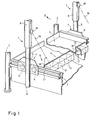
- a tub 1 for holding cheese mass stands on four columns 2, of which only two can be seen in FIG. 1. Not shown is located above the tub 1, known per se Press device, with the help of which is located in the tub 1 Cheese mass can be pressed together. This press device will go back to their above after the pressing operations the position of the tub 1 reset.
- the tub 1 can have a relatively large size, so that the pressed cheese mass in it then in individual cuboid must be divided, for this purpose is on the outside of the tub 1 on opposite sides Pages each have a horizontal guide in the form of two mutually parallel, approximately U-shaped guide rails 3 (only one is visible) mounted. But it goes without saying that such guidance is not essential as it would be possible, the arrangement described below also on Floor, next to the tub 1 or rails attached to the ceiling to let go.
- a carriage 4 travels in the guide rails 3 on each side, the essentially from a bearing plate 5 and mounted thereon Roll 6 exists.
- the carriage 4 can also one own drive, e.g. an engine acting on the wheels 6, like a stepper motor, but it can also be on the end shield 5 attack a linear drive, such as a fluidic cylinder, or the carriages 4 are simply along by hand the rails 3 adjustable. Another option would be in equipping the rails 3 with an electric linear motor.
- Each end shield 5 carries a linear actuator 7, which in itself as electrical drive could be formed, but preferably a fluidic drive, in particular a pneumatic cylinder 8 on a piston rod 9 attached to the end shield 5 is.
- This lifting drive carries a connecting strut 10 a cutting device, preferably in the form of a cutter bar 11.
- the cutter bar 11 it would also be conceivable to replace the cutter bar 11 to provide a cutting device movable in the manner of a saw, however, the cutter bar described below is 11 structurally simpler and more appropriate.
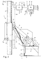
- the cutter bar 11 consists of a vertical cutter blade 12, which is lowered from above into the cheese mass, the Level in Fig. 2 by a horizontal, dash-dotted line K is displayed. On the vertical blade are in, preferably uniform, spacing dividing knife 13 attached. The knives 12, 13 are covered by a cover 14 'completed, to which the struts 10 attached are.
- a gripping device 14 solved, the one to enclose the cheese loader to the front Wall 15 and one on a continuous axis 16 this wall 15 has articulated gripping surface 17.
- a drive arm 18 is provided, which is only dashed lines in Fig. 1 indicated, but can be seen in Fig. 2 in detail. This drive arm supports the wall 15 and is on the strut 10 attached pivotally about an axis 19.
- This fixing device can by carried by the end walls 21 of the cutter bar 11, itself under the gripping surface 17 (preferably under one with this Area connected part) when they move into the closed position sliding retaining projection, it could be formed but also one, e.g. pneumatic, actuated, approximately along of the arm 18 downward movable locking bolt in the area of Axis 16 in this way behind the upwardly angled part 17 ' the gripping surface 17 can be moved so that it is in the closed position is fixed.
- the preferred pneumatic actuation can also be done in such a way that the respective one, here Not shown, pneumatic cylinder controlling valve (see valve block 32) is brought into a blocking position, i.e. either in a position in which the associated piston pressure medium is applied towards the blocking position or (e.g. with double-acting pistons) in a middle position, not in the pressure medium introduced into the cylinder can escape.
- the cutter bar 11 can cut out the row Cheese loader from the tub 1 by actuating the linear drive 7 remove.
- the linear drive 7 remove can be used for guidance, expediently on the rigid Piston rod 9 (Fig. 1), optionally also on a separate Guide profile 22 with the cylinder 8 with a carriage 23 Wheels 24, 25 may be provided.
- the carriage 23 works appropriately together with position sensors in the form of limit switches Pvu and Pvo, to ensure proper functioning.
- Similar Position sensors O and G can, as explained later is, for the open and closed position of the wall 15, e.g. can be provided on the swivel drive 20.
- the carriage 23 is attached to the cylinder 8 and carries one Console plate 26 on the one hand the strut 10 and on the other hand Cylinder unit of the swivel drive 20.
- a fastening foot 27 At the lower free End of the strut 10 is a fastening foot 27 with a easily detachable quick attachment 28 for the cutter bar 11 intended.
- the quick attachment can, as indicated, as Bayonet ring for engagement with a corresponding part of the Knife bar 11 in a bayonet slot of the ring or formed as a releasable snap connection in a known manner his. This makes it possible for cheese loaders to be different Sizes and / or shape of different cutter bars 11 on the fastening foot 27 to attach.
- bars 14 'on the cover To provide 29, which can be attached to the axis 19, for example can be attached.
- program device 30 is provided.
- the type of program device 30 is not essential to the invention, i.e. it could be, for example, a cam mechanism, punch cards or a series of contact disks that form one Orbits are driven.
- An electronic one is preferred Program device, e.g. with a microprocessor 30. This works in the present embodiment as follows.
- the first Step may be the command issued via a control line 31 to a transport device (not shown) for feeding Cheese mass in tub 1.
- This step will either timed (provided that the transport device for a uniform delivery per unit of time is formed), it can be controlled depending on the weight be by the tub 1, for example, on load cells stores or it can be a transport device with even Feed move over the tub 1, being a Limit switch at the end of this movement the complete filling the tub shows 1. In any case, this leads to one such advantageous training, to a signal V, the microprocessor 30 is delivered and there the next Triggers.
- a valve block 32 This valve block is connected to a fluid source 33, in particular a compressed air source, connected and distributed this fluid on the bottom the instructions of the microprocessor 30 at the given times different output lines. Accordingly, a Output line 34 a lowering of the pressing device against the caused in the tub 1 cheese mass.
- the process can in turn be timed by for lowering and pressing a predetermined one, by the clock of the microprocessor 30 is measured, or by limit switches, similar to the limit switches Pvo, Pvu des Cylinder 8, or it is one for lowering or pressing Step control circuit provided, the individual steps counted become.
- the pressing device moves up again, preferably via a fluidic like pneumatic, drive (whereby for the downward and the upward movement is a double-acting cylinder unit is provided) or by using the respective cylinder a return spring is equipped.
- a fluidic like pneumatic, drive whereby for the downward and the upward movement is a double-acting cylinder unit is provided
- a return spring is equipped.
- a line 35 can first a signal to a motor control of a travel drive for the wheels 6 of the car 4 are delivered to this in the to bring the correct starting position in each case. It was already said that instead of an electric drive also a fluidic drive can be provided, in which case the actuation will take place via the valve block 32. It is but clearly that some of the movements, like this positioning, could also be done by hand what but in the sense of a fully automated operation will generally not be preferred.
- valve block 32 receives a corresponding, e.g. binary coded, Command from microprocessor 30 and actuates the cylinder 8 via a line 37.
- the lower limit switch Pvu gives a signal when the carriage 23 arrives in the lower position from, which, as can be seen, fed to the microprocessor 30 becomes.
- the different knives have 12, 13 the cheese mass is cut to the bottom of the tub 1. Consequently the next step can be initiated.
- This step consists in first of all line 37 is also blocked against backflow of the fluid and via a Line 38 of the pivot cylinder 20 is actuated. That cylinder 20 causes a from the open position of the wall 15 Movement of the same in the direction of arrow P until that in FIG. 2 shown closed position is reached.
- the respective position of the swivel drive via appropriate sensors with output signals O and G to inform the microprocessor.
- Other options are mentioned above, namely a mere time-dependent control or a step control.
- the one attached to the struts Knife bar 11 not only raised and lowered, but also movable laterally with the aid of the cylinders 40, two Cases are conceivable: either the cutter bar is shorter, than it corresponds to the width of the tub 1; then can he in a similar way as he through the carriage 4 in one Is movable in the direction of the cylinder in the manner of a Also move the cross slide in a direction perpendicular to it so that the smaller one (and therefore easier to handling) knife bars nevertheless every place within the Tub 1 can reach.
- the horizontal drive 40 (and this is preferred) is used to remove the cutter bar 11 to move the areas of the tub 1 sideways so that its content held with the aid of the gripping surface 17 on a storage surface or a conveyor belt can be put down that to the side of the tub 1 is to be arranged.
- the knife bar 11 moved against the conveyor belt and by means of the unit 20 a movement in the opposite direction to the arrow P in FIG. 2 performed so that the cheese loader is down and to the side released, settle on the conveyor belt and so, e.g. to a packaging machine.
- the program 30 can also use means to control this horizontal drive 40, where the cylinders 40 based on a command from the microprocessor 30 (FIG. 2) via (at least) one line 42 from the valve block 32 can be controlled.
- the microprocessor then issues the command to the rotary actuator 20, in the open position (against the arrows P in Fig. 2) to drive the in the cutter bar 11 row of cheese loaders on the shelf or to store the conveyor belt. Then the cutter bar remain in the laterally extended position, so that the pressing device for the next cheese mass again can be lowered.
- the horizontal drive 40 instead of the Cylinders 8 to be attached, an independent, separate stored unit.
- the horizontal drive 40 instead of one cylinder at a time can also be another drive device for the horizontal Transverse movement can be arranged.
- that too Unloading the cutter bar 11 also by omitting the End walls 21 and by pushing through the cheese wheels the mentioned storage space take place, although such a solution is not preferred.
- the Cutter could be designed differently; for example could each use a single knife blade 12 the carriage 4 in one direction and then by means of in Carriages movable through this in the vertical direction the vertical cuts (instead of sheets 13) become.
- the wall and the gripping surface in the illustrated Embodiment are hinged to each other, so it would be but conceivable for the gripping surface 17 a separate drive to provide, or to form the wall 15 also as a knife blade and slide the gripping surface underneath.
- a separate drive to provide, or to form the wall 15 also as a knife blade and slide the gripping surface underneath.
- Another Variant can be that instead of cheese wheels triangular corners of cheese are cut out, for example by the Sheets 13, instead of parallel to each other, at an angle to each other to be ordered. By shaping the knife blades accordingly but other cookie cutters would also be possible.
Landscapes
- Life Sciences & Earth Sciences (AREA)
- Animal Husbandry (AREA)
- Environmental Sciences (AREA)
- Forests & Forestry (AREA)
- Engineering & Computer Science (AREA)
- Mechanical Engineering (AREA)
- Dairy Products (AREA)
- Treatment Of Fiber Materials (AREA)
- Beans For Foods Or Fodder (AREA)
- Confectionery (AREA)
Claims (9)
- Dispositif pour couper une masse de fromage prise en masse dans une cuve (1) et pour transporter les masses de fromage coupées sur une surface de réception, comportant un dispositif de coupe (11) qui comprend une lame verticale (12) et qui peut être levé et abaissé dans la masse de fromage au moyen d'un dispositif d'entraínement de levage (7, 8, 9), caractérisé en ce que le dispositif de coupe (11) peut être déplacé dans au moins une direction de cuve sur toute la cuve (1), la lame (12) est efficace transversalement sur toute la largeur de cuve et le dispositif de coupe (11) comprend un dispositif de retenue (15, 17, 20) avec une surface de prise (17) déplaçable sous la masse de fromage, le dispositif de retenue (15, 17, 20) retenant les masses de fromage coupées dans le dispositif de coupe (11) lors du mouvement de celui-ci du fond de la cuve vers le haut.
- Dispositif selon la revendication 1, caractérisé en ce qu'il est prévu au moins un deuxième dispositif d'entraínement (20, 40) pour déplacer au moins une partie du dispositif de coupe (11) et, pour coordonner les dispositifs d'entraínement, il est prévu de préférence un dispositif programmé (30) comme un microprocesseur.
- Dispositif selon la revendication 2, caractérisé en ce qu'un dispositif de pressage pour la masse de fromage se trouvant dans la cuve (1) peut aussi être commandé à l'aide du dispositif programmé (30).
- Dispositif selon la revendication 2 ou 3, caractérisé en ce qu'un dispositif d'alimentation pour amener une masse de fromage dans la cuve (1) peut aussi être commandé à l'aide du dispositif programmé (30).
- Dispositif selon l'une des revendications précédentes, caractérisé en ce qu'il est prévu une barre porte-lame (11) avec des lames (12, 13) perpendiculaires les unes aux autres et, de préférence, une paroi mobile (15) verticale en position fermée peut être mise contre un côté ouvert de la barre porte-lame à l'aide d'un dispositif de pivotement (20).
- Dispositif selon l'une des revendications précédentes, caractérisé en ce qu'une surface de prise (17) qui peut se glisser sous la masse de fromage peut être amenée à l'aide d'un dispositif d'entraínement (20) sous les morceaux de fromage découpés et peut être avantageusement bloquée dans cette position au moyen d'un dispositif de fixation commandable.
- Dispositif selon la revendication 6, caractérisé en ce que le dispositif de fixation peut être actionné de façon pneumatique par l'intermédiaire d'une soupape (32) le commandant et la soupape (32) peut être mise dans une position de blocage.
- Dispositif selon l'une des revendications précédentes, caractérisé en ce qu'un dispositif d'entraínement horizontal (40) est prévu pour un déplacement latéral du dispositif de coupe (11).
- Dispositif selon l'une des revendications précédentes, caractérisé en ce qu'un dispositif de déplacement horizontal (4) est prévu pour un déplacement parallèle du dispositif de coupe (11).
Applications Claiming Priority (3)
| Application Number | Priority Date | Filing Date | Title |
|---|---|---|---|
| CH319494 | 1994-10-25 | ||
| CH3194/94 | 1994-10-25 | ||
| CH319494 | 1994-10-25 |
Publications (2)
| Publication Number | Publication Date |
|---|---|
| EP0709021A1 EP0709021A1 (fr) | 1996-05-01 |
| EP0709021B1 true EP0709021B1 (fr) | 2001-01-24 |
Family
ID=4250697
Family Applications (1)
| Application Number | Title | Priority Date | Filing Date |
|---|---|---|---|
| EP95115055A Expired - Lifetime EP0709021B1 (fr) | 1994-10-25 | 1995-09-25 | Dispositif pour la coupe de masses de fromage |
Country Status (6)
| Country | Link |
|---|---|
| EP (1) | EP0709021B1 (fr) |
| AT (1) | ATE198816T1 (fr) |
| DE (1) | DE59508990D1 (fr) |
| DK (1) | DK0709021T3 (fr) |
| ES (1) | ES2154702T3 (fr) |
| FI (1) | FI108206B (fr) |
Families Citing this family (1)
| Publication number | Priority date | Publication date | Assignee | Title |
|---|---|---|---|---|
| DE102007037108B4 (de) * | 2007-08-03 | 2014-02-27 | Doma Gmbh | Antriebsanordnung für eine Lebensmittelteilvorrichtung |
Family Cites Families (10)
| Publication number | Priority date | Publication date | Assignee | Title |
|---|---|---|---|---|
| DE1193722B (de) * | 1964-03-04 | 1965-05-26 | Alpma Alpenland Maschb Ges Hai | Verfahren und Vorrichtung zum Ausformen von Kaesestuecken |
| CH438907A (de) * | 1966-06-21 | 1967-06-30 | Frey Wiederkehr & Cie Aktienge | Verfahren zum Ausstanzen von Zuschnitten aus einem Stapel blattförmigen Materials und Vorrichtung zur Durchführung des Verfahrens |
| DE2303159C3 (de) * | 1973-01-23 | 1979-01-04 | Kraft Gmbh, 6236 Eschborn | Vorrichtung zum Herstellen von Schnitt-Käse |
| FR2563692B1 (fr) * | 1984-05-04 | 1986-10-10 | Union Coop Agricole | Machine pour manutentionner des produits fragiles tels que du caille utilise dans la fabrication du fromage |
| US4705470A (en) * | 1985-02-27 | 1987-11-10 | Penta Angelo D | Cheese handling apparatus |
| FR2659044B1 (fr) * | 1990-03-02 | 1993-06-04 | Union Coop Agricole | Dispositif pour couper en cubes des denrees aliementaires et plus particulierement du fromage dur en boule. |
| FR2679736B1 (fr) * | 1991-08-02 | 1993-10-29 | Charlon Megard | Dispositif de moulage sous vide pour la fabrication des fromages a pates pressees cuites et demi-cuites. |
| DK172991A (da) | 1991-10-11 | 1993-04-12 | Apv Pasilac As | Forpresseapparat til forpresning og udskaering af osteblokke |
| JPH0741573B2 (ja) * | 1991-12-25 | 1995-05-10 | 節夫 新開 | 食品ユニット包装分断装置 |
| FR2707201A1 (fr) * | 1993-07-06 | 1995-01-13 | Ruebrecht Michel | Dispositif permettant la fabrication de montages alimentaires multicouches portionnés. |
-
1995
- 1995-09-25 EP EP95115055A patent/EP0709021B1/fr not_active Expired - Lifetime
- 1995-09-25 DK DK95115055T patent/DK0709021T3/da active
- 1995-09-25 ES ES95115055T patent/ES2154702T3/es not_active Expired - Lifetime
- 1995-09-25 AT AT95115055T patent/ATE198816T1/de not_active IP Right Cessation
- 1995-09-25 DE DE59508990T patent/DE59508990D1/de not_active Expired - Fee Related
- 1995-10-24 FI FI955067A patent/FI108206B/fi active
Also Published As
| Publication number | Publication date |
|---|---|
| DE59508990D1 (de) | 2001-03-01 |
| ATE198816T1 (de) | 2001-02-15 |
| FI108206B (fi) | 2001-12-14 |
| EP0709021A1 (fr) | 1996-05-01 |
| DK0709021T3 (da) | 2001-02-19 |
| FI955067L (fi) | 1996-04-26 |
| FI955067A0 (fi) | 1995-10-24 |
| ES2154702T3 (es) | 2001-04-16 |
Similar Documents
| Publication | Publication Date | Title |
|---|---|---|
| DE69309312T2 (de) | Verfahren und vorrichtung zum wechseln von formen in warmformpressen | |
| CH657797A5 (de) | Vorschubeinrichtung fuer blechtafeln. | |
| DE69405307T2 (de) | Maschine zum Einwickeln von Schalen in streckbarer Folie | |
| DE3418801A1 (de) | Arbeitsverfahren und vorrichtung zum saegen von profilen | |
| DE2127310C3 (de) | Fördereinrichtung für Flaschen oder ähnliches Fördergut | |
| EP0464296A2 (fr) | Installation pour couper une pièce et procédé de conduite de celle-ci | |
| DE2643507A1 (de) | Vorrichtung zum schrittweisen vorschub von platten | |
| CH622442A5 (fr) | ||
| DE1202620B (de) | Vorfuehr- und Austragvorrichtung fuer plattenfoermige Werkstuecke | |
| DE102012100586A1 (de) | Vorrichtung zum Schneiden und Verpacken von Brot | |
| DE3402567A1 (de) | Vorrichtung zum schneiden von stabmaterial, insbesondere von betonstahlstaeben | |
| DE2250087C3 (de) | Sicherheitsvorrichtung für eine Enthäutungs- oder Entschwartungsmaschine | |
| EP0536507B1 (fr) | Dispositif pour diviser une meule de fromage | |
| EP0297201B1 (fr) | Dispositif d'amenée d'éléments longitudinaux coupés à une certaine longueur à une soudeuse de treillis | |
| DE1939395B2 (de) | Magazinfülleinrichtung für Zigaretten weiterverarbeitende Maschinen | |
| EP0478530B1 (fr) | Cisaille pour le tronçonnage de grilles en tronçons de longueur choisie à volonté | |
| DE1652760B2 (de) | Fuer eine tafelschere fuer tafeln aus blech, kunststoff o.dgl. bestimmte vorrichtung zum unterstuetzen und abfuehren der geschnittenen tafeln | |
| DE1298358B (de) | Vorrichtung zum Abtrennen von Scheiben von einem Block aus Kaesebruch | |
| EP0709021A1 (fr) | Dispositif pour la coupe de masses de fromage | |
| DE2408822C2 (de) | Schneidvorrichtung für silogespeichertes Material | |
| DE2650690C2 (de) | Maschine zum Zerkleinern von Fleischerzeugnissen | |
| CH665159A5 (de) | Schleifmaschine. | |
| DE20022392U1 (de) | Senkrecht verschiebbare Schaumschwamm-Schneidevorrichtung | |
| AT403263B (de) | Maschinentisch mit einer unterflurkreissäge | |
| DE2724322A1 (de) | Vorrichtung zum zuschneiden und transportieren eines silageblockes |
Legal Events
| Date | Code | Title | Description |
|---|---|---|---|
| PUAI | Public reference made under article 153(3) epc to a published international application that has entered the european phase |
Free format text: ORIGINAL CODE: 0009012 |
|
| AK | Designated contracting states |
Kind code of ref document: A1 Designated state(s): AT CH DE DK ES FR GB IT LI NL SE |
|
| 17P | Request for examination filed |
Effective date: 19961004 |
|
| 17Q | First examination report despatched |
Effective date: 19990601 |
|
| GRAG | Despatch of communication of intention to grant |
Free format text: ORIGINAL CODE: EPIDOS AGRA |
|
| GRAG | Despatch of communication of intention to grant |
Free format text: ORIGINAL CODE: EPIDOS AGRA |
|
| GRAH | Despatch of communication of intention to grant a patent |
Free format text: ORIGINAL CODE: EPIDOS IGRA |
|
| GRAH | Despatch of communication of intention to grant a patent |
Free format text: ORIGINAL CODE: EPIDOS IGRA |
|
| ITF | It: translation for a ep patent filed | ||
| GRAA | (expected) grant |
Free format text: ORIGINAL CODE: 0009210 |
|
| AK | Designated contracting states |
Kind code of ref document: B1 Designated state(s): AT CH DE DK ES FR GB IT LI NL SE |
|
| REF | Corresponds to: |
Ref document number: 198816 Country of ref document: AT Date of ref document: 20010215 Kind code of ref document: T |
|
| REG | Reference to a national code |
Ref country code: CH Ref legal event code: NV Representative=s name: BUECHEL, VON REVY & PARTNER Ref country code: CH Ref legal event code: EP |
|
| REG | Reference to a national code |
Ref country code: DK Ref legal event code: T3 |
|
| REF | Corresponds to: |
Ref document number: 59508990 Country of ref document: DE Date of ref document: 20010301 |
|
| ET | Fr: translation filed | ||
| REG | Reference to a national code |
Ref country code: ES Ref legal event code: FG2A Ref document number: 2154702 Country of ref document: ES Kind code of ref document: T3 |
|
| GBT | Gb: translation of ep patent filed (gb section 77(6)(a)/1977) |
Effective date: 20010323 |
|
| PLBE | No opposition filed within time limit |
Free format text: ORIGINAL CODE: 0009261 |
|
| STAA | Information on the status of an ep patent application or granted ep patent |
Free format text: STATUS: NO OPPOSITION FILED WITHIN TIME LIMIT |
|
| REG | Reference to a national code |
Ref country code: GB Ref legal event code: IF02 |
|
| 26N | No opposition filed | ||
| PGFP | Annual fee paid to national office [announced via postgrant information from national office to epo] |
Ref country code: DE Payment date: 20020705 Year of fee payment: 8 |
|
| PGFP | Annual fee paid to national office [announced via postgrant information from national office to epo] |
Ref country code: ES Payment date: 20020710 Year of fee payment: 8 |
|
| PGFP | Annual fee paid to national office [announced via postgrant information from national office to epo] |
Ref country code: SE Payment date: 20020715 Year of fee payment: 8 |
|
| PGFP | Annual fee paid to national office [announced via postgrant information from national office to epo] |
Ref country code: FR Payment date: 20020716 Year of fee payment: 8 |
|
| PGFP | Annual fee paid to national office [announced via postgrant information from national office to epo] |
Ref country code: DK Payment date: 20020821 Year of fee payment: 8 |
|
| PGFP | Annual fee paid to national office [announced via postgrant information from national office to epo] |
Ref country code: GB Payment date: 20020913 Year of fee payment: 8 |
|
| PGFP | Annual fee paid to national office [announced via postgrant information from national office to epo] |
Ref country code: AT Payment date: 20020916 Year of fee payment: 8 |
|
| PGFP | Annual fee paid to national office [announced via postgrant information from national office to epo] |
Ref country code: NL Payment date: 20020930 Year of fee payment: 8 |
|
| PGFP | Annual fee paid to national office [announced via postgrant information from national office to epo] |
Ref country code: CH Payment date: 20021024 Year of fee payment: 8 |
|
| PG25 | Lapsed in a contracting state [announced via postgrant information from national office to epo] |
Ref country code: GB Free format text: LAPSE BECAUSE OF NON-PAYMENT OF DUE FEES Effective date: 20030925 Ref country code: AT Free format text: LAPSE BECAUSE OF NON-PAYMENT OF DUE FEES Effective date: 20030925 |
|
| PG25 | Lapsed in a contracting state [announced via postgrant information from national office to epo] |
Ref country code: SE Free format text: LAPSE BECAUSE OF NON-PAYMENT OF DUE FEES Effective date: 20030926 Ref country code: ES Free format text: LAPSE BECAUSE OF NON-PAYMENT OF DUE FEES Effective date: 20030926 |
|
| PG25 | Lapsed in a contracting state [announced via postgrant information from national office to epo] |
Ref country code: LI Free format text: LAPSE BECAUSE OF NON-PAYMENT OF DUE FEES Effective date: 20030930 Ref country code: DK Free format text: LAPSE BECAUSE OF NON-PAYMENT OF DUE FEES Effective date: 20030930 Ref country code: CH Free format text: LAPSE BECAUSE OF NON-PAYMENT OF DUE FEES Effective date: 20030930 |
|
| PG25 | Lapsed in a contracting state [announced via postgrant information from national office to epo] |
Ref country code: NL Free format text: LAPSE BECAUSE OF NON-PAYMENT OF DUE FEES Effective date: 20040401 Ref country code: DE Free format text: LAPSE BECAUSE OF NON-PAYMENT OF DUE FEES Effective date: 20040401 |
|
| EUG | Se: european patent has lapsed | ||
| REG | Reference to a national code |
Ref country code: DK Ref legal event code: EBP |
|
| GBPC | Gb: european patent ceased through non-payment of renewal fee |
Effective date: 20030925 |
|
| REG | Reference to a national code |
Ref country code: CH Ref legal event code: PL |
|
| PG25 | Lapsed in a contracting state [announced via postgrant information from national office to epo] |
Ref country code: FR Free format text: LAPSE BECAUSE OF NON-PAYMENT OF DUE FEES Effective date: 20040528 |
|
| NLV4 | Nl: lapsed or anulled due to non-payment of the annual fee |
Effective date: 20040401 |
|
| REG | Reference to a national code |
Ref country code: FR Ref legal event code: ST |
|
| REG | Reference to a national code |
Ref country code: ES Ref legal event code: FD2A Effective date: 20030926 |
|
| PG25 | Lapsed in a contracting state [announced via postgrant information from national office to epo] |
Ref country code: IT Free format text: LAPSE BECAUSE OF NON-PAYMENT OF DUE FEES Effective date: 20050925 |