EP0709048B1 - Mécanisme d'un repose-pieds en combinaison avec une chaise - Google Patents
Mécanisme d'un repose-pieds en combinaison avec une chaise Download PDFInfo
- Publication number
- EP0709048B1 EP0709048B1 EP19950202728 EP95202728A EP0709048B1 EP 0709048 B1 EP0709048 B1 EP 0709048B1 EP 19950202728 EP19950202728 EP 19950202728 EP 95202728 A EP95202728 A EP 95202728A EP 0709048 B1 EP0709048 B1 EP 0709048B1
- Authority
- EP
- European Patent Office
- Prior art keywords
- support
- auxiliary frame
- frame
- footrest mechanism
- drive
- Prior art date
- Legal status (The legal status is an assumption and is not a legal conclusion. Google has not performed a legal analysis and makes no representation as to the accuracy of the status listed.)
- Expired - Lifetime
Links
- 230000007246 mechanism Effects 0.000 title claims description 39
- 238000010276 construction Methods 0.000 description 2
- 206010046996 Varicose vein Diseases 0.000 description 1
- 244000309466 calf Species 0.000 description 1
- 230000000284 resting effect Effects 0.000 description 1
- 208000027185 varicose disease Diseases 0.000 description 1
Images


Classifications
-
- A—HUMAN NECESSITIES
- A47—FURNITURE; DOMESTIC ARTICLES OR APPLIANCES; COFFEE MILLS; SPICE MILLS; SUCTION CLEANERS IN GENERAL
- A47C—CHAIRS; SOFAS; BEDS
- A47C7/00—Parts, details, or accessories of chairs or stools
- A47C7/50—Supports for the feet or the legs
- A47C7/506—Supports for the feet or the legs of adjustable type
Definitions
- the invention concerns a built-in footrest mechanism in combination with a chair, said mechanism comprising a support which can be moved between a folded-in position in which it is situated under the seat and a position in which it is situated in front of the seat; a frame which is mounted under the seat in the chair; an auxiliary frame which is telescopic in relation to said frame and upon which the support is movably mounted; and a common drive for sliding the above-mentioned auxiliary frame in and out and for moving the support in relation to this auxiliary frame.
- Such a footrest mechanism makes it possible to bring the support, upon which is provided a cushion or such, in front of the seat, so that a person resting in the chair can put his feet on this cushion.
- the support is a part of the front of the chair situated under the seat which can be folded out forward, for example by means of a shear mechanism.
- a footrest mechanism of this kind is for example disclosed in US-A-3.794.381.
- the support is pivotaly connected to the front and the drive can pivot the support from its vertical position in the front of the chair to a horizontal position just in front of the seat.
- the support in folded-out position, is situated practically against the seat, which in many cases is not an ideal position to support the feet.
- the calves rather than the feet rest on the support, which is for example undesirable for people suffering from varicose veins.
- the invention aims to provide a built-in footrest mechanism in a chair which fits in several chairs and which can bring the support in the suitable place in relation to the seat and yet has quite a simple construction.
- this aim is reached because the support is connected to the telescopic auxiliary frame by the intermediary of a tilting connection containing on each side a pair of arms whose ends are connected in a hinged manner to the auxiliary frame and in a hinged manner to the support, whereby the drive is connected to the tilting connection
- EP-A-0.534.908 discloses a footrest mechanism comprising a support connected by the intermediary of two pair of arms to a telescopic auxiliary frame mounted on a fixed frame.
- this mechanism does not comprise any drive and as well the telescoping of the auxiliary frame as the tilting of the support are manually.
- the footrest mechanism according to the invention contains means which, when the drive extends this auxiliary frame, hold the support in its lowest position on this auxiliary frame until this auxiliary frame is almost completely extended.
- These means may consist of clamping means, in particular of at least a spring.
- the invention also concerns the footrest mechanism as such which is fit to be built-in in a chair.
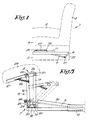
- Figure 1 schematically represents a chair 1 which mainly consists of an underside 2 carrying a seat 3, a back 4 and two armrests 5.
- a footrest mechanism is built-in in the underside 2 which mainly consists of a frame 6 which is fixed in the underside 2, an auxiliary frame 7 which is telescopic in relation to said frame 6, a support 8 which is mounted adjustable in height on the auxiliary frame 7 and a common drive 9 to slide the auxiliary frame 7 in and out and to move the support 8 up and down in relation to the auxiliary frame.
- the auxiliary frame 7 can be slid in and out in relation to the frame 6 by means of two horizontal telescopic arms 10 which each consist of two rails 11 and 12 which can slide into one and other with a C-shaped section and a profile 13 with an L-shaped section which can slide in the rails 11 and 12.
- the rails 11 are fixed to or are part of the frame 6 which is connected to the underside 2 of the chair 1 as represented in figure 7.
- the L-shaped profiles 13 are fixed to or are part of the auxiliary frame 7 and they are connected to one another with their ends by means of a cross piece 14.
- the distance between the telescopic arms 10 can, as represented in the figures, be smaller than the width of the underside 2, in which case these arms 10 are fixed by the frame 6 to this underside 2.
- the support 8 is mounted adjustable in height on the cross piece 14 by means of a tilting connection 15 which mainly consists of two pair of arms 16-17 on either side of the footrest mechanism.
- the arms 16 and 17 of each pair are two laths which, together with two L-shaped profiles 18 and 19 form a deformable polygon which hinges in its corners.
- the ends of these arms 16 and 17 are connected in a hinged manner by horizontal hinge pens 20 which are directed in the cross direction in relation to the telescopic arms 10, to the L-shaped profile 18 on the one hand and to the L-shaped profile 19 on the other hand.
- the profiles 18 and 19 which are parallel to the telescopic arms 10 are directed such than hinge pens 20 belonging to a profile 18 or 19 are situated one after the other at the same height in the longitudinal direction of the arms 10.
- the L-shaped profile 18 is fixed to the cross piece 14 whereas the other L-shaped profile 19 is fixed to the underside of the support 6.
- the drive 9 consists of an electric jack which is fixed to the frame 6 under the telescopic arms 10 by means of a hinge pen 21 and an L-shaped profile 22 on the one hand, and which is hinge-mounted to the arms 16 of the two pairs 16-17 of the tilting connection 15 by means of a fork 23 and a shaft 24 sticking through it whose ends are borne in L-shaped pieces 25 which are fixed to the arms 16 on the other hand.
- the shaft 24 is situated somewhat higher than the lowest hinge pens 20 with which the arms 16 hinge in relation to the cross piece 14, so that the arms 16 can be tilted by sliding the drive 9 in or out.
- the support 6 mainly consists of a cross plate 26 which is carried by the two L-shaped profiles 19 and a forwardly directed arm 27 which is fixed to the cross plate 26 and is situated almost in line with the L-shaped profile 19 on one side.
- clamping means which consist of a spring 28 which is fixed to this arm 27 on the one hand and to a protrusion of the arm 16 of one of the pairs 16-17 of the tilting connection 15 on the other hand.
- This spring 28 is a draw spring which draws the arm 27 towards the arm 16, as a result of which the tilting connection 15 tends to tilt downward. Consequently, the spring 28 forms means which try to bring the support 6 into a bottommost position and oppose the tilting upward of the tilting connection 15.
- the tractive effort can be adjusted by removing the fastening point of the spring 28 to the arm 27.
- This arm 27 is provided to this end with a number of openings in which an end of the spring 28 can catch.
- a cushion 29 can be fixed on the support 8.
- the drive 9 formed by the electric jack can be protected by a U-shaped cap 30.
- the footrest mechanism In folded-in position, the footrest mechanism is in the position as represented in the figures 1, 6 and 7, whereby the telescopic arms 10 are slid in and the support 8 is situated in its lowest position on these telescopic arms 10. The entire footrest mechanism is then situated in the underside 2 of the chair 1 under the seat 3.
- the drive 9 is activated. Although this drive 9 acts on the arms 16 of the tilting connection 15 through the medium of the shaft 24, these arms 16 will not be tilted immediately due to the presence of the spring 28.
- the support 8 remains in its lowest position and only the telescopic arms 10 are extended first.
- the spring 28 forms means which not only try to move the support 8 downward, but which also prevent the support 8 from being moved upward by the drive 9 as long as the auxiliary frame 7 is not fully extended and the support 8 is not situated in front of the underside 2.
- the upward tilting of the tilting connection 15 is restricted thanks to the maximum extension of the jack which forms the drive 9.
- This connection 15 is represented in figures 3 and 5 in its maximally tilted position.
- the support 8 In this position, the support 8 is in its highest position, in front of the seat 3, almost in line with this seat.
- the jack which forms the drive 9 is slid in again. Due to the spring 28, the support 8 will hereby be brought down first, after which the auxiliary frame 7 is slid in due to the sliding in of the telescopic arms 10.
- the design of the above-described footrest mechanism is quite simple.
- the support 8 and thus also the cushion 29 mounted upon it cannot only be put in the required height, but also at the required distance in front of the seat 3.
- the footrest mechanism is relatively compact and can be built-in in different chair models.
- the total width of this footrest mechanism without the frame 6 is smaller than the width of the underside 2 of a normal chair.
- By means of an adjusted frame 6 it can be fixed to the broader underside.
- the auxiliary frame 7 must not necessarily have a cross piece 14.
- the two pair of arms 16 and 17 of the tilting connection 15 can be fixed directly to the telescopic arms 10, so that the auxiliary frame 7 can be practically restricted to the telescopic profiles 13 of these arms 10.
Landscapes
- Chairs For Special Purposes, Such As Reclining Chairs (AREA)
- Passenger Equipment (AREA)
Claims (7)
- Mécanisme de repose-pied intégré en combinaison avec un fauteuil (1), ledit mécanisme comprenant un support (8) qui peut passer d'une position rentrée à l'état replié dans laquelle il est situé en dessous du siège (3) et une position dans laquelle il est situé devant le siège (3); un cadre (6) qui est monté en dessous du siège (3) dans le fauteuil (1); un cadre auxiliaire (7) télescopique par rapport audit cadre (6) et sur lequel le support (8) est monté en mobilité; et une commande commune (9) pour faire glisser le cadre auxiliaire (7) susmentionné vers l'intérieur et vers l'extérieur et pour déplacer le support (8) par rapport à ce cadre auxiliaire (7), caractérisé en ce que le support (8) est relié au cadre auxiliaire télescopique (7) par l'intermédiaire d'une liaison de basculement (15) contenant de part et d'autre une paire de bras (16 et 17) dont les extrémités sont reliées en articulation au cadre auxiliaire (7) et en articulation au support (8), la commande (9) étant reliée à liaison de basculement (15).
- Mécanisme de repose-pied selon la revendication 1, caractérisé en ce qu'il contient des moyens (28) qui, lorsque la commande (9) étend ce cadre auxiliaire (7), maintiennent le support (8) dans sa position la plus basse sur ce cadre auxiliaire (7) jusqu'à ce que ce cadre auxiliaire (7) se soit étendu de manière pratiquement complète, lesdits moyens (28) s'opposant au basculement vers le haut de la liaison de basculement (15).
- Mécanisme de repose-pied selon la revendication 2, caractérisé en ce que ces moyens (28) contiennent un ressort (28).
- Mécanisme de repose-pied selon la revendication 3, caractérisé en ce que le support (8) contient un bras (27) orienté vers l'avant et en ce que le ressort (28) est un ressort de traction qui est fixé à ce bras (27) d'une part et à la liaison de basculement (15) d'autre part.
- Mécanisme de repose-pied selon l'une quelconque des revendications précédentes, caractérisé en ce que la commande (9) est un vérin électrique qui est monté entre le cadre (6) et la liaison de basculement (15).
- Mécanisme de repose-pied selon les revendications 4 et 5, caractérisé en ce que le ressort (28) est monté entre un bras antérieur (16) de la liaison de basculement (15) et le bras (27) du support (8), tandis que le vérin de la commande (9) est monté en articulation sur le bras antérieur (16) susmentionné autour d'un pivot qui est disposé plus haut que l'axe d'articulation (20) avec lequel ce bras (16) s'articule par rapport au cadre auxiliaire (7).
- Mécanisme de repose-pied selon l'une quelconque des revendications précédentes, caractérisé en ce que le cadre auxiliaire (7) peut glisser à l'intérieur et à l'extérieur du cadre (6) à l'aide de deux bras télescopiques (10) dont les parties extensibles (13) font partie du cadre auxiliaire (7) ou sont fixées à ce dernier et dont les parties (11) font partie du cadre (6) ou sont fixées à ce dernier.
Applications Claiming Priority (4)
| Application Number | Priority Date | Filing Date | Title |
|---|---|---|---|
| BE9400974A BE1008845A3 (nl) | 1994-10-26 | 1994-10-26 | In een zitmeubel geintegreerde voetbank en mechanisme daarvan. |
| BE9400974 | 1994-10-26 | ||
| BE9500279 | 1995-03-29 | ||
| BE9500279A BE1008855A6 (nl) | 1995-03-29 | 1995-03-29 | In een zitmeubel ingebouwd voetbankmechanisme en daarvoor bestemd voetbankmechanisme. |
Publications (2)
| Publication Number | Publication Date |
|---|---|
| EP0709048A1 EP0709048A1 (fr) | 1996-05-01 |
| EP0709048B1 true EP0709048B1 (fr) | 2000-01-26 |
Family
ID=25662935
Family Applications (1)
| Application Number | Title | Priority Date | Filing Date |
|---|---|---|---|
| EP19950202728 Expired - Lifetime EP0709048B1 (fr) | 1994-10-26 | 1995-10-10 | Mécanisme d'un repose-pieds en combinaison avec une chaise |
Country Status (2)
| Country | Link |
|---|---|
| EP (1) | EP0709048B1 (fr) |
| DE (1) | DE69514754D1 (fr) |
Family Cites Families (2)
| Publication number | Priority date | Publication date | Assignee | Title |
|---|---|---|---|---|
| US3794381A (en) * | 1971-10-26 | 1974-02-26 | D Caldemeyer | Footrest for reclining chair |
| IT222726Z2 (it) * | 1991-09-17 | 1995-04-24 | Magix Snc Di Xodo Gino & C | Struttura di poltrona o divano con accessorio poggiapiedi portaoggetti o simile |
-
1995
- 1995-10-10 DE DE69514754T patent/DE69514754D1/de not_active Expired - Lifetime
- 1995-10-10 EP EP19950202728 patent/EP0709048B1/fr not_active Expired - Lifetime
Also Published As
| Publication number | Publication date |
|---|---|
| EP0709048A1 (fr) | 1996-05-01 |
| DE69514754D1 (de) | 2000-03-02 |
Similar Documents
| Publication | Publication Date | Title |
|---|---|---|
| US5984338A (en) | Lightweight stabilized raising chair | |
| US4143910A (en) | Chair having synchronously coupled tiltable seat and back rest | |
| US5911469A (en) | Folding adirondack chair | |
| EP1411801B1 (fr) | Ameliorations apportees a et par rapport a des chaises et des lits reglables | |
| US5765797A (en) | Articulated support for computers and the like | |
| US20050017559A1 (en) | Seat elevating mechanism for chair | |
| US5337857A (en) | Ladder adaptable platform | |
| US5735570A (en) | Foldable chair frame | |
| EP1011384B1 (fr) | Fauteuil | |
| US5195194A (en) | Seat-bed extender | |
| US5653502A (en) | Foldable chair | |
| US20030075967A1 (en) | Raisable leg rest | |
| US20200015594A1 (en) | Adjustment device for a headrest | |
| EP0179748A2 (fr) | Chaise de travail | |
| US4217670A (en) | Foldable rail assembly | |
| US4660883A (en) | Safety platform arrangement for recliner | |
| EP0709048B1 (fr) | Mécanisme d'un repose-pieds en combinaison avec une chaise | |
| WO1997046144A1 (fr) | Chaise pour position assise ou du type assis-debout | |
| US5046571A (en) | Vertically adjustable wheel chair | |
| CN215650139U (zh) | 一种沙发机架及沙发 | |
| GB2303058A (en) | Folding chair | |
| US20040211344A1 (en) | Sofa table with adjustable height | |
| HU213146B (en) | Seat convertible into a bed | |
| BE1008855A6 (nl) | In een zitmeubel ingebouwd voetbankmechanisme en daarvoor bestemd voetbankmechanisme. | |
| GB2203937A (en) | Collapsible chairs |
Legal Events
| Date | Code | Title | Description |
|---|---|---|---|
| PUAI | Public reference made under article 153(3) epc to a published international application that has entered the european phase |
Free format text: ORIGINAL CODE: 0009012 |
|
| AK | Designated contracting states |
Kind code of ref document: A1 Designated state(s): BE CH DE DK FR GB IT LI LU NL |
|
| 17P | Request for examination filed |
Effective date: 19961104 |
|
| 17Q | First examination report despatched |
Effective date: 19981123 |
|
| GRAG | Despatch of communication of intention to grant |
Free format text: ORIGINAL CODE: EPIDOS AGRA |
|
| GRAG | Despatch of communication of intention to grant |
Free format text: ORIGINAL CODE: EPIDOS AGRA |
|
| GRAH | Despatch of communication of intention to grant a patent |
Free format text: ORIGINAL CODE: EPIDOS IGRA |
|
| GRAH | Despatch of communication of intention to grant a patent |
Free format text: ORIGINAL CODE: EPIDOS IGRA |
|
| GRAA | (expected) grant |
Free format text: ORIGINAL CODE: 0009210 |
|
| AK | Designated contracting states |
Kind code of ref document: B1 Designated state(s): BE CH DE DK FR GB IT LI LU NL |
|
| PG25 | Lapsed in a contracting state [announced via postgrant information from national office to epo] |
Ref country code: LI Free format text: LAPSE BECAUSE OF FAILURE TO SUBMIT A TRANSLATION OF THE DESCRIPTION OR TO PAY THE FEE WITHIN THE PRESCRIBED TIME-LIMIT Effective date: 20000126 Ref country code: IT Free format text: LAPSE BECAUSE OF FAILURE TO SUBMIT A TRANSLATION OF THE DESCRIPTION OR TO PAY THE FEE WITHIN THE PRESCRIBED TIME-LIMIT;WARNING: LAPSES OF ITALIAN PATENTS WITH EFFECTIVE DATE BEFORE 2007 MAY HAVE OCCURRED AT ANY TIME BEFORE 2007. THE CORRECT EFFECTIVE DATE MAY BE DIFFERENT FROM THE ONE RECORDED. Effective date: 20000126 Ref country code: FR Free format text: LAPSE BECAUSE OF FAILURE TO SUBMIT A TRANSLATION OF THE DESCRIPTION OR TO PAY THE FEE WITHIN THE PRESCRIBED TIME-LIMIT Effective date: 20000126 Ref country code: CH Free format text: LAPSE BECAUSE OF FAILURE TO SUBMIT A TRANSLATION OF THE DESCRIPTION OR TO PAY THE FEE WITHIN THE PRESCRIBED TIME-LIMIT Effective date: 20000126 |
|
| REG | Reference to a national code |
Ref country code: CH Ref legal event code: EP |
|
| REF | Corresponds to: |
Ref document number: 69514754 Country of ref document: DE Date of ref document: 20000302 |
|
| PG25 | Lapsed in a contracting state [announced via postgrant information from national office to epo] |
Ref country code: DK Free format text: LAPSE BECAUSE OF FAILURE TO SUBMIT A TRANSLATION OF THE DESCRIPTION OR TO PAY THE FEE WITHIN THE PRESCRIBED TIME-LIMIT Effective date: 20000426 |
|
| PG25 | Lapsed in a contracting state [announced via postgrant information from national office to epo] |
Ref country code: DE Free format text: LAPSE BECAUSE OF FAILURE TO SUBMIT A TRANSLATION OF THE DESCRIPTION OR TO PAY THE FEE WITHIN THE PRESCRIBED TIME-LIMIT Effective date: 20000427 |
|
| EN | Fr: translation not filed | ||
| REG | Reference to a national code |
Ref country code: CH Ref legal event code: PL |
|
| PG25 | Lapsed in a contracting state [announced via postgrant information from national office to epo] |
Ref country code: LU Free format text: LAPSE BECAUSE OF NON-PAYMENT OF DUE FEES Effective date: 20001010 Ref country code: GB Free format text: LAPSE BECAUSE OF NON-PAYMENT OF DUE FEES Effective date: 20001010 |
|
| PGFP | Annual fee paid to national office [announced via postgrant information from national office to epo] |
Ref country code: NL Payment date: 20001031 Year of fee payment: 6 |
|
| PGFP | Annual fee paid to national office [announced via postgrant information from national office to epo] |
Ref country code: BE Payment date: 20001106 Year of fee payment: 6 |
|
| PLBE | No opposition filed within time limit |
Free format text: ORIGINAL CODE: 0009261 |
|
| STAA | Information on the status of an ep patent application or granted ep patent |
Free format text: STATUS: NO OPPOSITION FILED WITHIN TIME LIMIT |
|
| 26N | No opposition filed | ||
| GBPC | Gb: european patent ceased through non-payment of renewal fee |
Effective date: 20001010 |
|
| PG25 | Lapsed in a contracting state [announced via postgrant information from national office to epo] |
Ref country code: BE Free format text: LAPSE BECAUSE OF NON-PAYMENT OF DUE FEES Effective date: 20011031 |
|
| BERE | Be: lapsed |
Owner name: SANTERMANS GASTON Effective date: 20011031 |
|
| PG25 | Lapsed in a contracting state [announced via postgrant information from national office to epo] |
Ref country code: NL Free format text: LAPSE BECAUSE OF NON-PAYMENT OF DUE FEES Effective date: 20020501 |
|
| NLV4 | Nl: lapsed or anulled due to non-payment of the annual fee |
Effective date: 20020501 |